1
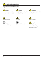
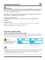
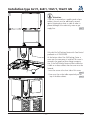
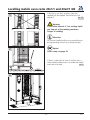
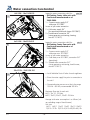
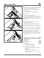
Installation Manual
Safety instructions
Explanations of the icon's
Danger!
Immediate dangerous situation,
that can endanger severe injury
or death
Warning!
Possibly dangerous situation, that
possibly can endanger severe
injury or death.
Attention!
Possibly dangerous situation, that
can endanger minor injury.
Corrosive substances
Fire hazard!
Danger of burning!
Attention: Inobservance can
cause material damages.
Tips and tricks for installation
V11
-2-
Danger!
High voltage.
Caution danger of life
Inobservance can endanger
severe injury or death.
Safety instructions
Warning!
Wrong installation, service, maintenance or cleaning as well as unauthorized changes on the unit can
cause damages, injuries or even death. Read the installation manual carefully before installing the unit.
This unit may only be used for preparing food in commercial kitchens. Every other usage is against definition and therefore dangerous.
Warning!
Only gas units
- If the unit is installed underneath an extraction hood, it must be made sure that the hood is switched
on during operation of the unit – Waste gases!
- If the gas unit is connected to a chimney, it must be made sure that the exhaust line will be cleaned on
a regular basis subject to local regulations – Fire hazard! (For this purpose also contact the installer)
- Don't put any material on the exhaust pipes of the unit – Fire hazard!
- The area underneath the unit may not be blocked or closed by any material– Fire hazard!
- The unit may only be operated in a calm environment – Fire hazard!
Safety measures in case of smell of gas:
- Immediately close the gas supply.
- Don't touch any electrical switching element
- ventilation of the room.
- Avoid open flame or sparks
- Use an external telephone and inform your local gas authority (in case the local gas authority can not
be reached inform the operation centre of the fire brigade).
-3-
V11
Dear customer
The warranty excludes glass damage, light bulbs and sealing material as well as damage caused by
improper use, installation,maintenance, repair by untrained/unqualified personnel and scaling of components
We reserve the right to make technical changes in the interest of progress!
Quote in the event of a query:
Dealer
Appliance model:
Appliance no.:
______________________________________
Installer
Set to gas type:
______________________________________
Your appliance was checked by:
Safety stickers „Max. rack height for containers with liquid“ are in the Starter Kit.
After Installation of the unit, this sticker has
to be fixed to the unit in a height of
1600 mm (see examples)
1600 (63")
1600 (63")
______________________________________
Warning
To avoid scalding, do not use loaded containers with liquids or cooking goods which becomes fluid by
heating in higher levels than those which can be easily observed. (DIN: IEC 60335-2-42)
Danger of scalding!
V11
-4-
Installation instructions
Attention:
The named standards are valid for Germany. In all other countries follow the local standards and
valid instructions. Damages based on installation not complying with the directives given hereunder are not covered by warranty terms.
The requisite connections (water, electricity, gas) must only be carried out by suitably qualified technicians in compliance with local regulations.
Check for any transport damage.
Should there be any signs of transport damage, inform your dealer/freight forwarder
immediately!
Dumping of old units.
At the end of its service life, the unit must not be disposed of with the general waste and must not be
placed in the recycling containers at local authority collection points.
We will be happy to help you with the disposal of your unit.
First time commissioning
valid for SelfCooking® Center with CareControl
When commissioning your new, intelligent SelfCooking Center® for the first time, you will be asked to start
an automatic self test. The duration of this self test is approximately 15 minutes and is necessary to adapt
the SelfCooking Center® to the specific environmental conditions.
Fire hazard!
Remove packing material, starter
kit as well as containers and
grids from intereior cabinet.
11:30
m
s
11:29
m
s
Start
Start
close cabinet door
Press Start-key, Self test is running, remaining running time is
shown
Leave hinged racks respectively mobile oven racks inside the cabinet, Interior cabinet door must not be
opened during the complete process of the self test. Opening the interior cabinet door interrupts the self
test and when switching on the unit the next time you will be asked to start the self test again.
This procedure does not apply to Combi Master units.
-5-
V11
Table of content
Installation Manual
Safety instructions
Safety instructions
Dear customer
Installation instructions
Table of content
Table of content
Transport of units
Recommended minimum clearance
Installation type 6x1/1, 6x2/1, 10x1/1, 10x2/1 GN
Installation type 6x1/1, 6x2/1, 10x1/1, 10x2/1 GN
Installation Type 20x1/1 GN, 20x2/1 GN
Levelling mobile oven racks 20x1/1 and 20x2/1 GN
Electrical connection
Electrical connection
Water connection CareControl
Water connection
Selection of water filter
Selection of water filter
Gas connection pictures
Gas connection
Gas connection / Gas consumption
Drain connection
Ventilation, technical data, heat emission
Option
Option
Option
Mobile floor models 20x1/1GN and 20x2/1GN
Mobile floor models 20x1/1GN and 20x2/1GN
Mobile floor models 20x1/1GN and 20x2/1GN
Mobile floor models 20x1/1GN and 20x2/1GN
Mobile floor models 20x1/1GN and 20x2/1GN
Mobile floor models 20x1/1GN and 20x2/1GN
Connected loads in accordance with VDE Guideline
Conversion tables
V11
1
2
3
4
5
6
7
8
9
10
11
12
13
14
15
16
17
18
19
20
21
22
23
24
25
26
27
28
29
30
31
32
33
34
35
-6-
Table of content
Schematic drawing 6x1/1 GN CareControl
Schematic drawing 6x1/1 GN Gas CareControl
Schematic drawing 6x2/1 GN CareControl
Schematic drawing 6x2/1 GN Gas CareControl
Schematic drawing 10x1/1 GN CareControl
Schematic drawing 10x1/1 GN Gas CareControl
Schematic drawing 10x2/1 GN CareControl
Schematic drawing 10x2/1 GN Gas CareControl
Schematic drawing 6x1/1 GN
Schematic drawing 6x1/1 GN Gas
Schematic drawing 6x2/1 GN
Schematic drawing 6x2/1 GN Gas
Schematic drawing 10x1/1 GN
Schematic drawing 10x1/1 GN Gas
Schematic drawing 10x2/1 GN
Schematic drawing 10x2/1 GN Gas
Schematic drawing 20x1/1 GN
Schematic drawing 20x1/1 GN Gas
Schematic drawing 20x2/1 GN
Schematic drawing 20x2/1 GN Gas
Schematic drawing 20x1/1 GN Electric, mobile
Schematic drawing 20x1/1 GN Gas, mobile
Schematic drawing 20x2/1 GN Electric, mobile
Schematic drawing 20x2/1 GN Gas, mobile
36
37
38
39
40
41
42
43
44
45
46
47
48
49
50
51
52
53
54
55
56
57
58
59
-7-
V11
Transport of units
Transport of units
Transport of units using a pallet
1
6x1/1 GN:
920mm/36 1/4"
6x2/1 GN:
1120mm/44 1/8"
10x1/1 GN:
920mm/36 1/4"
10x2/1 GN:
1120mm/44 1/8"
Transport of units without a pallet, 20x1/1 GN and
20x2/1 GN units only. Put a piece of wood between
pallet jack and left guide rail of the trolley
pic. 3, 4
Attention
Make sure that the unit is secured against
tilting, when transporting it.
2
20x1/1 GN:
950mm/37 1/2"
20x2/1 GN:
1150mm/45 1/4"
3
20x1/1 GN:
920mm/36 1/4"
20x2/1 GN:
1140mm/45"
Remove all containers/mobile oven racks from the
cabinet. For floor model, remove corner mountings
from the pallet. Take unit off the pallet.
Attention
Observe the weight of the units.
Use carrying aid to avoid injuries.
Wear safety boots.
Weight see technical data on page 24
Observe door height
pic. 5
X= Required door width when transporting units
without pallet:
6x1/1GN 840 mm (33 1/8”)
6x2/1GN 1040 mm (41”)
10x1/1GN 840 mm (33 1/8”)
10x2/1GN 1040 mm (41”)
20x1/1GN 920 mm (36,1/4”)
20x2/1GN 1140-mm (45“)
4
5
20x1/1 GN /
20x2/1 GN:
1900mm/75"
Center
of Gravity
F
r
o
n
t
V11
pic. 1,2
D
o
o
r
/1GN)
X (6x1/1 - 20x2
2x2", 50x50mm
-8-
Recommended minimum clearance
1
Minimum clearance left/ right/ rear 50 mm (2”)
(except floor models).
pic. 1
50mm/2"
50mm/2"
50mm/2"
On floor models (20x1/1 GN and 20x2/1 GN) there
must be a minimum clearance of 500 mm (approx
20”) on the left side of the unit, for installing the
power cable
Minimum clearance when there are heat sources
on the left-hand side is 350 mm (14”).
pic 2
2
Attention:
A safety shut down can occur if the ambient
temperature on the left hand side of the unit is
too high.
Option:
Heat shield see page 25
≥ 350mm
14"
3
50mm/2"
500mm/
20"
50mm/2"
We recommend a distance of 500 mm (20”) on the
left hand side of the unit for carrying out
maintenance work.
pic. 3
Attention:
- Do not install deep fat fryer at the rear side of
the unit.
- The units must only be installed in frost-free
rooms.
-9-
V11
Installation type 6x1/1, 6x2/1, 10x1/1, 10x2/1 GN
Because of safety reasons table units shall only be
installed on original stands of the manufacturer.
In this case the maximum rack height is
1600 mm (63")
1
2
A 6x1/1 /10x1/1 GN: 745,5mm (29 3/8")
6x2/1 10x2/1 GN: 965,5mm (38")
A
64,5mm
2 5/8"
64,5mm
2 5/8"
If Gas units are installed on a table or on the
kitchen floor (combi duo) then:
a) press the retaining plates (ET-No.:12.00.519)
into the lower part of the pedestal and fasten
with the enclosed nuts.
b) the plate must be fitted to the surface using
either screws and dowels or studs and nuts or
the special adhesive.
pic. 1
The retaining plates are not included in the
scope of supply
Attention: The centre height of the drain pipe is
63 mm (2 1/2”). When installing combi duo
observe the drain height of the bottom unit.
+
_ 10mm
5006.0213
3
+
_ 10mm
Option:
Using 110 mm (4 3/8”) legs and height
adjustable transport trolley for extended
space underneath unit. See page 25
Stands for gas appliances must be fixed to the
floor using the fixing set part no.: 8700.0317
either with screws and dowels, or with the special
adhesive supplied.
pic. 2
Fixing set is not included in the scope of supply,
Slide the stand into the fixing brackets and level it.
Place the unit on the stand. The feet of the unit
must be secured by means of the locating pins of
the stand
pic. 3
4
V11
Ensure that the unit is level
- 10 -
pic. 4
Installation type 6x1/1, 6x2/1, 10x1/1, 10x2/1 GN
1
Attention:
If the unit is mounted on a mobile stand or base
cabinet, the unit must be additionally secured
against slipping by a chain or cable in order to
prevent damage to the electricity, water or gas
supply line.
pic. 1
2
Only valid for SelfCooking Center with CareControl
produced as of 28.09.2008:
At the bottom side of the SelfCooking Center a
cover over the care pump is installed. This cover is
secured in the upper position during transportation. If the SelfCooking Center will be installed on
a table or on base cabinet then the cover must be
lowered.
- Loose the screw at the front side of this cover
pic. 2
- Cover must lay on the table respectively on the
top of the base cabinet.
pic. 3
3
- 11 -
V11
Installation Type 20x1/1 GN, 20x2/1 GN
Installation type 20x1/1 GN, 20x2/1 GN
Ensure that the unit is level
1
pic. 1
Fix the floor locks, (supplied with the fixing set) to
the floor with either screws and pins or with the
special adhesive.
pic. 2
Next slide the unit into the floor locks
pic. 2
The mobile oven rack must be level when
standing inside the unit
pic. 3
2
Attention: Observe height of the drain pipe
+
_ 10mm
Option:
Using leg extension for more space underneath unit.
Install height extension for mobile oven
rack see page 26
A 20x1/1 GN: 732,5 mm / 28 7/8"
20x2/1 GN: 937,5 mm / 37"
A
64,5mm
2 5/8"
64,5mm
2 5/8"
5006.02
13
3
V11
- 12 -
Levelling mobile oven racks 20x1/1 and 20x2/1 GN
If the floor is not level, an access ramp (not
supplied) will be required. The incline must not
exceed 4°.
pic. 1,2
1
Warning:
If the incline exceeds 4°, hot cooking liquid
can slop out of the cooking containers.
Danger of scalding!
Attention:
An incorrect levelled trolley can cause malfunction
during operating the unit (e. g. during Cleanjet)
2
Option:
Access ramp see page 26
If there is a drain grill in front of the floor unit, a
ramp should be placed over it to enable the mobile
oven rack to be used.
pic. 3
max 4
3
- 13 -
V11
Electrical connection
1
5 mm
2
L
1 L
2 L
3 N
Danger
Observe local regulations and standards
during installation
General information see next page
Electrical units
s¬ ¬%ACH¬APPLIANCE¬REQUIRES¬AN¬INDEPENDENT¬FUSED¬
power supply line
s¬ ¬!¬PERMANENT¬ELECTRICAL¬CONNECTION¬MUST¬BE¬
provided for the units.
Units manufactured as of 01.08.2007 can either
be connected permanent or by using a plug
s¬ ¬4ABLE¬UNITS¬8¬'.¬¬8¬'.¬ARE¬
equipped with a power cable, which is directly
connected to the main contactor. The cable
comes without plug and is approx. 2,5 m (8 ft)
long.
Warning
Observe colour coding of the wires. Wrong
connection can cause electric shock
3
4
V11
Attention:
Wrong connection can cause damages (e. g. fan
motor)
s¬ #OLOUR¬CODING¬OF¬WIRES¬
yellow/green = earth
blue = neutral
brown, grey or black = Phase L1, L2, L3
s¬ ¬&LOOR¬UNITS¬8¬'.¬AND¬8¬'.¬ARE¬
delivered without power cable
s¬ ¬4HE¬MAIN¬CONTACTOR¬TABLE¬UNITS¬AND¬THE¬MAIN¬
terminals (floor models) are located in the
electrical compartment and are accessible after
removing the left side panel.
pic. 1/2
- 14 -
Electrical connection
Gas units
s¬ ¬7E¬RECOMMEND¬AN¬INDEPENDENT¬FUSED¬POWER¬
supply line.
s¬ ¬!¬PERMANENT¬ELECTRICAL¬CONNECTION¬MUST¬BE¬
provided for the units.
s¬ ¬!LL¬UNITS¬ARE¬EQUIPPED¬WITH¬A¬POWER¬CABLE¬WITHout plug, approx. 2,5 m (8 ft) long.
s¬ 4HE¬MAIN¬TERMINALS¬ARE¬LOCATED¬IN¬THE¬ELECTRICAL¬
compartment and are accessible after removing
the left side panel.
pic. 1/2
s¬¬5NIT¬SHOULD¬BE¬CONNECTED¬TO¬A¬FUSED¬SPUR¬
observe local electrical regulations
s¬ !TTENTION
Observe polarity of the mains!
No burner function with wrong polarity!
s¬ ¬/NSITE¬INSTALLATION¬PROVIDE¬ACCESSIBLE¬ALLPOLE¬
disconnection device with a minimum of a 3 mm
contact gap.
s¬ ¬4HE¬CIRCUIT¬DIAGRAM¬IS¬LOCATED¬BEHIND¬THE¬HINGED¬
control panel.
s¬ 3PECIAL¬VOLTAGES¬AVAILABLE¬ON¬REQUEST
s¬ ¬4HE¬CROSSSECTION¬OF¬THE¬POWER¬CABLES¬MUST¬BE¬
based on the current consumption and on local
regulations.
s¬ !PPLICABLE¬STANDARDS¬%.¬¬)%#¬
s¬ &OR¬ELECTRICAL¬CONNECTION¬DATA¬SEE¬PAGE¬
s¬¬"EFORE¬DISCONNECTING¬OR¬RECONNECTING¬UNIT¬%NSURE¬
electrical supply is isolated.
For appliance connections, precise
dimensions and connection points, see pages
36 and following.
Warning
Observe colour coding of the wires. Wrong
connection can cause electric shock
Attention:
Wrong connection can cause damages (e. g. fan
motor)
s¬ ¬#OLOUR¬CODING¬OF¬THE¬POWER¬CABLE¬
yellow/green = earth, blue = Neutral
brown, grey or black = Phase L1 (L2)
Gas and electrical units
s¬ ¬4HE¬STUD¬FOR¬THE¬EARTH¬BONDING¬IS¬LOCATED¬ON¬
the bottom side, underneath the control panel.
Connect the wire for the earth bonding
to this stud.
pic. 3/4
General information:
s¬ ¬&OLLOW¬THE¬INSTALLATION¬INSTRUCTIONS¬AND¬THE¬
information on the rating plate when connecting
the unit.
s¬ ¬#OMPLY¬WITH¬ALL¬LOCAL¬REGULATIONS¬AND¬STANDARDS
s¬ ¬7E¬RECOMMEND¬AN¬INDEPENDENT¬FUSED¬POWER¬
supply line for each appliance.
s¬ ¬5NITS¬MUST¬BE¬CONNECTED¬TO¬AN¬EARTH¬LEAKAGE¬
circuit breaker.
Power cable :
s¬ ¬4HE¬EXCHANGE¬OF¬THE¬POWER¬CABLE¬MAY¬ONLY¬BE¬
carried out by the manufacturer, his service
agents or similar qualified personal
Electrical units
s¬ ¬#ONNECT¬AN¬(2.&¬SUPPLY¬CABLE¬MINIMUM¬
tighten the cable gland and the strain relief
s¬ #ONNECT¬THE¬SUPPLY¬AS¬FOLLOWS
Grey terminal:
L1, L2, L3 (non-phase-sequence-dependent)
Blue terminal: Neutral (only 3N AC)
Yellow/green terminal: Earth connection
Gas:
s¬ ¬5NITS¬THE¬POWER¬CABLE¬HAS¬TO¬BE¬EXCHANGED¬A¬
power cable with the following minimum quality
has to be used:
H05 RN-F 3x2,5 mm2
s¬)F¬THE¬GAS¬UNIT¬X¬¬X¬'.¬IS¬PROTECTED¬
by means of a safety cut-out it must observe that
this cut-out is at least of characteristic “C”.
- 15 -
V11
Water connection CareControl
6x1/1GN - 10x1/1GN E/G
1
3
2
1
6x2/1GN - 10x2/1GN E/G
2
3
1
2
Legend to water connections valid for:
pic. 1/2
- SelfCooking Center table units with
CareControl manufactured as of
28.09.2008:
1 = Common water supply 3/4”
cold water 30°C/86°F
In case of split water connection
2 = Cold water supply 3/4”
(for quenching and hand shower 30°C/86°F).
3 = Treated water connection 3/4”
(steam generator, moistening, cleaning,
max. 60 °C/140°F).
Legend to water connections valid for:
pic. 3
- SelfCooking Center floor units with
CareControl manufactured as of
28.09.2008:
1 = Common water supply 3/4”
cold water max. 30°C/86°F
In case of split water connection
2 = Cold water, max 30°C/86°F, connection 3/4”
(quenching)
3 = Treated water connection 3/4”
(steam generator, moistening, hand shower,
max 60°C/140°F)
20x1/1GN - 20x2/1GN E/G
s¬ ¬)NSTALL¬INDIVIDUAL¬SHUTOFF¬VALVE¬FOR¬EACH¬APPLIANCE
3
s¬ ¬2INSE¬THE¬WATER¬SUPPLY¬LINE¬PRIOR¬TO¬CONNECTION¬TO¬
the unit!
s¬ ¬#ONNECTED¬WATER¬PRESSURE¬MUST¬BE¬IN¬THE¬RANGE¬
150 kPa - 600 kPa, recommended 300 kPa
3
1
2
Maximum flow rate for each unit
6x1/1, 10x 1/1: 20 l/min
6x2/1, 10x2/1, 20x1/1, 20x2/1: 25 l/min
Average total water consumption is as follows (values excluding usage of hand shower)
Unit size:
6x1/1 6x2/1 10x1/1 10x2/1 20x1/1 20x2/1
12,0 l/h 32 l/h 25,2 l/h 41,4 l/h 49,8 l/h 60,0 l/h
V11
- 16 -
Water connection
Note:
The manufacturer recommends especially on model
Combi Master a preventive check of your
equipment 6 months after installation to determine
actual scale build up.
This should be done by a trained technician.
4
3
1
Water treatment:
For filter selection see pages 18/19
Treated water with a water hardness less than 6 °e
may not be supplied, because such water can react
aggressive and corrosive which can reduce the life
cycle of the unit.
2
5
Connecting SelfCooking Center to water with
hardness less than 8,75°e:
To avoid an excessive build up of foam the soft
water switch should be set to "ON" in the basic
settings. This can be done by a trained technician.
3
2
1
In most cases it is not necessary to install a filter
or water treatment for water supply. The integrated
SC-automatic changes the water in the steam
generator at regular intervals automatically.
However under certain water conditions different
filter applications (A, B, C, D see page 18) might
be necessary.
6
2
3
1
Legend to water connections valid for:
pic. 4-6
- SelfCooking Center without CareControl:
- Combi Master
Floor models
pic. 4
Table models electric
pic. 5
Table models gas
pic. 6
1 = Common water supply 3/4”
cold water max. 30°C/86°F
In case of split water connection
2 = Cold water, max 30°C/86°F, connection 3/4”
(quenching)
3 = Treated water connection 3/4”
(steam generator, moistening, hand shower,
max 60°C/140°F)
- 17 -
V11
Selection of water filter
Please consult your local water supply board
for advise on chlorine (Cl2), chloride (Cl-)
and hardness of the water
1
30C/86F
A)Particle filter
pic. 1/2
When the water contains sand, iron particles or
suspended matter, we recommend a 5-15 μm
(micro meter) particle filter:
300 kPa
43,5 psi
F
I
L
T
E
R
300 kPa
43,5 psi
max. 60C/140F
B)Active carbon filter
pic. 1/2
When the level of chlorine (Cl2) in the water
exceeds 0.2 mg/l (= ppm) (information available
from the water company), an active carbon filter
should be installed.
30C/86F
300 kPa
43,5 psi
2
2
3
150-600kpa
21,75-87 psi R 3/4"
R3/4"
150-600kpa
21,75-87 psi
3/4"
1/2"
1/2"
A
C)Complete De-Ionization
pic. 1/2
When the water has a chloride Cl- concentration
above 70 mg/l (= 70 ppm), a complete
deionization system should be installed to avoid
corrosion.
Note: Make sure a minimum conductivity of
50 μS/cm (micro Siemens) remains in the water.
B
C
D 3/4"
max. 60°C
max. 140°F
D)Water softener:
pic. 1/2
Valid for SelfCooking Center with
CareControl
These models will remove scale all by itself providing that the units are used as prescribed.
These means a water softener is not needed.
Valid for SelfCooking Center without
CareControl and Combi Master:
A water softener is recommended when a high
level of scale (not containing chloride) is
experienced.
Systems recommended: H+ Ion Exchanger.
Sodium ion exchangers (as used in dishwashers)
must not be used.
Treated water with a water hardness less than
6 °e may not be supplied, because such water
can react aggressive and corrosive which can
reduce the life cycle of the unit.
Amongst others the following filter manufacturers
offer adequate filter applications:
Brita, Falk.
V11
- 18 -
Selection of water filter
Important for treated water connection:
Split the water supply to standard and treated
water connection for each unit to extend filter
capacity!
See pictures 1/2/3 page 16
Remove T-connection at water inlet
Connect cold untreated water to inlet position “2”
Connect treated water to inlet position “3”
Filter capacity:
Average treated water consumption is as follows
(values excluding usage of hand shower)
6x1/1 6x2/1 10x1/1 10x2/1 20x1/1 20x2/1
3,0 l/h 8 l/h 6,3 l/h 10,4 l/h 12,5 l/h 15,0 l/h
Maximum flow rate 16 l/min
Important for filter connection:
Water supply hose / pipe size 1/2” minimum
Connection to filter : 3/4”
If a combination of filters is fitted, the sequence
A-B and C or D of the filters in the direction of
flow must be observed
pic. 2
- 19 -
V11
Gas connection pictures
1
6x1/1 GN: 3/4"
6x2/1 GN: 3/4"
10x1/1 GN: 3/4"
10x2/1 GN: 3/4"
5
RATIONAL
! mbar
6
2
20x1/1 GN: 3/4"
20x2/1 GN: 3/4"
! mbar
7
3
4
180 mm
7 1/4”
V11
- 20 -
Gas connection
Important!
To ensure that the burner settings made at the factory conform with the actual installation conditions, the
waste gas (C0, C02) from the steam and hot-air burners must be analysed during commissioning. The
corresponding values must be documented inside the unit. If the undiluted C0 values are above 1000 ppm,
the burner settings must be checked and if necessary adjusted by engineers trained and certified by the
company.
Warning
Incorrect connection can engender
fire hazard!
Comply with local gas authority regulations!
Follow installation instructions!
s¬ ¬#HECK¬THAT¬THE¬GAS¬TYPE¬SUPPLIED¬IS¬SUITABLE¬FOR¬
the unit.
s¬ ¬4HE¬DIAMETER¬OF¬THE¬PIPE¬MUST¬COMPLY¬WITH¬LOCAL¬
regulations
s¬ ¬)NNER¬THREAD¬OF¬GAS¬CONNECTION¬
PIC¬
s¬ ¬'AS¬STOP¬VALVE¬SUPPLIED¬FOR¬EACH¬UNIT
s¬ ¬'AS¬CONNECTION¬WITH¬GAS¬OUTLET¬SOCKET¬IS¬
possible.
s¬ ¬!LL¬GAS¬SUPPLY¬CONNECTORS¬MUST¬COMPLY¬WITH¬LOCAL¬
regulations.
s¬ ¬4HE¬UNIT¬MUST¬BE¬SECURED¬AGAINST¬MOVEMENT
s¬ ¬#HECK¬THE¬GAS¬SUPPLY¬LINE¬FOR¬LEAKAGE¬ PIC¬
Attention:
s¬ ¬4HE¬UNIT¬IS¬ONLY¬TO¬BE¬CONNECTED¬TO¬THE¬GAS¬
supply by a locally approved gas installer. It is
vital to ensue that the gas connection pipes as
well as the connection pipes for the associated
gas metering systems match the stipulated pipe
widths.
s¬ ¬)F¬THE¬FLOW¬PRESSURE¬DEVIATES¬FROM¬THE¬SPECIFIED¬
flow pressure (see table), inform the gas authorities. If the flow pressure of natural gas exceeds
30 mbar (12,04 in w. c.), the unit must not be
switched on and the gas supply must be disconnected.
s¬¬¬Attention: The gas parts are designed for a maximum flow pressure of 65 mbar (26,09 in w. c.)
Type A3, B13, B23 gas unit
A3: Ambient-air-dependent gas-powered cooking range with fan assisted burners without
exhaust collector.
For UK market can be used when replacing
similar equipment in kitchens where instal-
lation of the air inlet/extraction was prior to
September 2001 & providing there is a documented risk assessment to ensure that there
will always be sufficient make-air and extraction available when running the equipment.
Please observe Current Gas Regulations.
B13 Ambient-air-dependent gas-powered cooking
range with fan assisted burners with exhaust
collector.
B23 Ambient-air-dependent gas-powered cooking range with fan assisted burners without
exhaust collector.
s¬¬!UTOMATIC¬DIRECT¬IGNITION¬WITH¬IGNITION¬MONITOR
Installation of draft diverter
pic. 4
The draft diverter is not shipped with the unit, but
can be ordered under the following part numbers:
Unit size:
Art. Nos.:
6x1/1 GN
70.00.396
6x2/1 GN
70.00.398
10x1/1 GN
70.00.397
10x2/1 GN
70.00.399
20x1/1 GN
70.00.400
20x2/1 GN
70.00.401
Gas exhaust system
s¬¬4HE¬MINIMUM¬CLEARANCE¬TO¬THE¬CEILING¬OF¬THE¬
exhaust pipes is 200 mm
s¬¬#HECK¬THAT¬GAS¬EXHAUST¬PIPES¬ARE¬LEAK¬PROOF¬IN¬
accordance with local regulations
s¬¬7ASTE¬GAS¬PIPES¬OF¬ALUMINIUM¬OR¬OTHER¬MATERIALS¬
which are not resistant to temperatures up to
200°C should not be used because of the high
waste gas temperatures!
Gas exhaust system can be connected to the
following:
(observe your local regulations)
1. Extractor hood
pic. 5
2. Fan roof
pic. 6
3. Directly into the flue
pic. 7
- 21 -
V11
Gas connection / Gas consumption
Room ventilation
Warning
The rooms in which these appliances are installed must be well ventilated, in order to prevent an unacceptable build-up of harmful combustion products.
Danger of suffocation!
We recommend to service the gas units at least once a year in accordance with the specified standards
Gas consumption
Gas type
Required
flowpressure
Nat. gas H G20
Nat. gas L G25
18-25 mbar
20-30 mbar
LPG G30
LPG G31
25-57,5 mbar
25-57,5 mbar
Gas type
Required
flowpressure
Nat. gas H G20
Nat. gas L G25
18-25 mbar
20-30 mbar
LPG G30
LPG G31
25-57,5 mbar
25-57,5 mbar
Wobbe index
(15°C, 1013mbar)
Wi
Ws
MJ/m3
MJ/m3
45,67
50,72
37,38
41,52
MJ/m3
MJ/m3
80,58
87,33
74,75
81,19
Wobbe index
(15°C, 1013mbar)
Wi
Ws
MJ/m3
MJ/m3
45,67
50,72
37,38
41,52
MJ/m3
MJ/m3
80,58
87,33
74,75
81,19
max. consumption on nominal heat load
6x1/1 GN
11 kW
1,2 m3/h
1,4 m3/h
12 kW
1,01 kg/h
1,04 kg/h
6x2/1 GN
21,5 kW
2,3 m3/h
2,6 m3/h
23 kW
1,93 kg/h
2,03 kg/h
10x1/1 GN
21,5 kW
2,3 m3/h
2,6 m3/h
23 kW
1,93 kg/h
2,03 kg/h
max. consumption on nominal heat load
10x2/1 GN
32 kW
3,4m3/h
3,9 m3/h
34 kW
2,86 kg/h
3,01 kg/h
20x1/1 GN
43 kW
4,6 m3/h
5,3 m3/h
46 kW
3,86 kg/h
4,05 kg/h
20x2/1 GN
64 kW
6,8 m3/h
7,9m3/h
67 kW
5,63 kg/h
6,03 kg/h
Exhaust gas- and room volume
Unit size
Room size free ventilation
Room size permanent ventilation
Combustion air supply
Waste gas volume
Waste gas temperature
6x1/1 GN
44,0 m3
22,0 m3
17,6 m3/h
31,4 m3/h
310°C
6x2/1 GN
86,0 m3
43,0 m3
34,4 m3/h
81 m3/h
450°C
10x1/1 GN
86,0 m3
43,0 m3
34,4 m3/h
76,6 m3/h
490°C
10x2/1 GN
128,0 m3
64,0 m3
51,2 m3/h
116 m3/h
460°C
20x1/1 GN
172,0 m3
86,0 m3
68,8 m3/h
140,6 m3/h
390°C
20x2/1 GN
256 m3
128 m3
102,4 m3/h
233.3 m3/h
465°C
Free ventilation
= Combustion air supply through windows and doors
Permanent ventilation = Combustion air supply by two openings to the outside with a free cross section
of 150 cm2 (one opening near the ceiling, the other opening near the floor)
Attention: Data are calculated under German standards
Room size free ventilation = 4 x Kilowatt power of the unit
(e. g. unit 6x1/1 GN: 11KW x 4 = 44 m3)
Room size permanent ventilation = 2 x Kilowatt power of the unit (e. g. unit 6x1/1 GN: 11KW x 2 = 22 m3)
Combustion air supply = 1,6 x Kilowatt power of the unit
(e. g. unit 6x1/1 GN: 11KW x 1,6 = 17,6 m3/h)
Observe local regulation/standards for calculating the values!
V11
- 22 -
Drain connection
1
200-300mm
(8 - 12 “)
3x45°
250-300mm
(10 - 12 “)
min. 3° / 5%
Ø 50mm (2”)
max. 1m
(3 ft.)
2
min. 3° / 5%
Ø 50mm (2”)
70mm
(2 3/4“)
max. 1m
(3 ft.)
3
s¬ ¬4HE¬APPLIANCE¬COMPLIES¬WITH¬THE¬RELEVANT¬
regulations (DVGW, SVGW, KIWA, WRC)
Attention
Use pips capable of withstanding steam temperature, don't use hoses
s¬ ¬$RAINWATER¬CONNECTION¬SET¬
Art. no.: 60.70.464
s¬ 7ELDING¬OF¬DRAIN¬PIPE¬TO¬THE¬UNITS¬DRAIN¬IS¬NOT¬
permissible (welding can cause damages to the
unit)
s¬ ¬$.¬¬PIPE with constant gradient (min. 5% or
3°); do not reduce the diameter of the pipe.
s¬ ¬&IXED¬CONNECTION¬WITH¬ODOUR¬LOCK¬PERMISSIBLE¬A¬
ventilated drain line is integral to the
appliance
pic. 1,2
s¬ ¬7HERE¬THERE¬IS¬AN¬EXISTING¬FLOOR¬DRAIN¬WITHOUT¬AIR¬
trap, a clear outflow of 2 cm (1”) must be
provided.
pic. 3
¬s¬ ¬7E¬RECOMMEND¬TO¬CONNECT¬EVERY¬UNIT¬TO¬A¬SEPArate drain.
s¬ ¬5NITS¬X'.¬UP¬TO¬X'.¬CAN¬BE¬CONnected either to a wall drain or to a floor drain
s¬ 5NITS¬X'.¬OR¬X'.¬CAN¬ONLY¬BE
connected to a floor drain.
Option: For reduction of steam escape
via the ventilation pipe a condensate collector or an additional ascending pipe can be
used. See pages 26/27
Option table models:
Using 110 mm (approx. 4”) legs for extended space underneath unit. Height adjustable
transport trolley, see page 25
Option floor models:
Using leg extension for more space underneath unit. Install height extension for
mobile oven rack see page 26
Note drainage dimensions: short-term pumped discharge volume of steam generator 0.7 l/sec (0,18
gal/sec.)
s¬ ¬!VERAGE¬WASTE¬WATER¬TEMPERATURE¬ª#
s¬ ¬!PPLICABLE¬STANDARD¬$).¬¬0ART¬
Attention: The centre height drain pipe of table
models is 63 mm (2 1/2”) and floor models is
70 mm (2 7/8”).
- 23 -
V11
Ventilation, technical data, heat emission
Ventilation:
An exhaust hood is not essential. If one is fitted, bear the following points in mind:
s¬ ¬#OMPLY¬WITH¬ALL¬LOCAL¬REGULATIONS¬AND¬STANDARDS
s¬ ¬4HE¬HOOD¬SHOULD¬PROJECT¬¬MM¬¬FT¬IN¬FRONT¬OF¬THE¬APPLIANCE
s¬ ¬)NSTALL¬A¬GREASE¬FILTER¬IN¬THE¬PROJECTING¬PART¬OF¬THE¬HOOD
s¬ ¬!N¬EXHAUST¬HOOD¬IS¬AVAILABLE¬AS¬AN¬OPTION¬FOR¬X¬¬X¬'.¬UNITS¬
s¬ &OR¬INSTALLATION¬OF¬THE¬HOOD¬PLEASE¬FOLLOW¬THE¬INSTRUCTION¬OF¬THE¬CORRESPONDING¬INSTALLATION¬MANUAL¬
Technical data:
Noise emission level:
<70dBA
Hoseproofness:
IPX5
Heat emission:
Electrical units: 6x1/1 GN
latent:
2.143 kJ/h
sensible:
2.727 kJ/h
6x2/1GN
4.167 kJ/h
5.000 kJ/h
10x1/1 GN
3.529 kJ/h
4.615 kJ/h
10x2/1 GN
6.667 kJ/h
9.474 kJ/h
20x1/1 GN
7.200 kJ/h
9.000 kJ/h
20x2/1 GN
12.500 kJ/h
14.286 kJ/h
Gas units:
latent:
sensible:
6x2/1GN
4.167 kJ/h
5.000 kJ/h
10x1/1 GN
3.529 kJ/h
4.286 kJ/h
10x2/1 GN
6.667 kJ/h
9.231 kJ/h
20x1/1 GN
7.200 kJ/h
8.780 kJ/h
20x2/1 GN
11.583 kJ/H
13.636 kJ/H
6x1/1 GN
2.143 kJ/h
2.571 kJ/h
Weight of electric units:
SCC units:
6 x 1/1 GN: 110,0 kg
6 x 2/1 GN: 142,5 kg
10 x 1/1 GN: 135,5 kg 10 x 2/1 GN: 182,0 kg
20 x 1/1 GN: 258,0 kg 20 x 2/1 GN: 332,0 kg
Mobile:
20 x 1/1 GN: 275,5 kg 20 x 2/1 GN: 352,0 kg
Weight of gas units:
SCC units:
6 x 1/1 GN: 126,0 kg
10 x 1/1 GN: 154,5 kg
20 x 1/1 GN: 286,0 kg
Mobile:
20 x 1/1 GN: 303,5 kg
CM units without
6 x 1/1 GN: 99,0 kg
10 x 1/1 GN: 124,5 kg
20 x 1/1 GN: 251,5 kg
6 x 2/1 GN: 133,0 kg
10 x 2/1 GN: 175,5 kg
20 x 2/1 GN: 326,0 kg
20 x 1/1 GN: 269,0 kg
20 x 2/1 GN: 346,0 kg
6 x 2/1 GN: 168,0 kg
10 x 2/1 GN: 198,0 kg
20 x 2/1 GN: 370,5 kg
CM units without
6 x 1/1 GN: 121,0 kg
10 x 1/1 GN: 148,0 kg
20 x 1/1 GN: 261,0 kg
6 x 2/1 GN: 158,5 kg
10 x 2/1 GN: 189,5 kg
20 x 2/1 GN: 369,5 kg
20 x 2/1 GN: 390,5 kg
20 x 1/1 GN: 278,5 kg
20 x 2/1 GN: 389,5 kg
Right of technical modifications reserved.
V11
- 24 -
Option
Heat shield left and right
1
50
mm
Unit size:
6x1/1GN
6x1/1GN
10x1/1GN
10x1/1GN
6x2/1GN
10x2/1GN
20x1/1GN
20x2/1GN
Art.-No.: 60.70.390 left
Art.-No.: 60.70.736 right
Art.-No.: 60.70.391 left
Art.-No.: 60.70.743 right
Art.-No.: 60.70.392
Art.-No.: 60.70.393
Art.-No.: 60.70.394
Art.-No.: 60.70.395
If the minimum required distance to heat sources
on the left or right side (right side only 6x1/1 GN
and 10x1/1 GN) can not be maintained a heat
shield will help to reduce the heat stress to the unit
pic 1
2
Height extension of table units.
3
(6x1/1 GN up to 10x2/1GN)
Should the distance between floor and bottom of
table units be too low (e.g. when installing combi
duo), then the standard lower parts of the legs can
be replaced by longer legs (110 mm).
Art.-No.: 12.00.224
pic. 2
Attention: In this case the height of the upper rail
in the cooking cabinet exceeds 1600 mm (63”)
When using mobile oven racks and transport
trolleys the height difference can be compensated
by a height adjustable transport trolley.
pic. 3
Height adjustable trolley:
Unit size:
6x1/1 and 10x1/1 GN
Art.-No.: 60.60.188
6x2/1 and 10x2/1 GN
Art.-No.: 60.70.160
- 25 -
V11
Option
1
2
3
Foot extension for floor units
Art.-No.: 60.21.179
Should the distance be too low between floor and
bottom of floor units , foot extensions for
floor units can be used
pic 1
Attention: In this case the height of the upper rail
exceeds 1600 mm (63”).
When using these foot extensions a height
compensation of the mobile oven rack must be
carried out by adding an additional frame. pic. 2
20x1/1GN
Art.-No.: 60.21.184
20x2/1GN
Art.-No.: 60.22.184
Ramp for mobile oven rack floor
models
20x1/1GN
Art.-No.: 60.21.080
20x2/1GN
Art.-No.: 60.22.181
If the floor underneath the unit is not level the
mobile oven rack ramp can level out this
uneveness. The adjustment range of the legs is
between +/- 10 mm .
pic. 3
4
V11
Condensation breaker
Under critical installation conditions (e.g. installation in front kitchens), escape of steam at the vent
pipe can be reduced by fitting a condensation
breaker
pic. 4
Unit size:
6x1/1GN / 10x1/1GN
Art.-Nos.: 8710.1309
- 26 -
Option
Also for reducing the steam escape at the drain
pipe an additional vent pipe can be fitted to the
drain pipe. In this extra vent pipe holes must be
drilled where air is sucked in and condensates the
steam
pic 1/2
1
2
8 mm
1/8"
Interfaces
a) A serial interface (RS232) is not standard, but
can be retrofitted into all units.
Unit size
6x1/1GN - 10x2/1GN
Art.-No.: 87.00.006
20x1/1GN - 20x2/1GN
Art.-No.: 87.00.007
b) SCC units are equipped with USB interface as a
standard.
- 27 -
V11
Mobile floor models 20x1/1GN and 20x2/1GN
Attention:
The following warning stickers are affixed to the unit:
Sticker:
"Don't push on operator panel"
Sticker:
"Don't pull on door handle"
Sticker:
Observe
before transport of unit
When moving the unit the following must be observed:
1. Don`t push at the operator panel. This can destroy the control unit behind it.
2. Don`t pull the unit using the door handle, this can damage the door lock mechanism.
Prior to the transport of the unit observe the following
procedure:
1. Read installation and/or user manual.
2. Disconnect all supply lines at the unit to avoid damages.
3. Move unit only by using the handle
V11
- 28 -
Mobile floor models 20x1/1GN and 20x2/1GN
Sticker:
"Danger of tipping over"
Sticker:
"Danger of tipping over"
Sticker:
"Attention: For taking the unit off
of the pallet at least 2 persons are
necessary"
Sticker:
"Attention: For taking the unit off
of the pallet at least 2 persons are
necessary"
When moving the unit the power cord must be secured against damage, therefore at the top rear side of
the unit the enclosed holding device must be installed.
- Undo the tapping screw at the left rear side and fasten the holding device with the screw to the top
cover.
- 29 -
V11
Mobile floor models 20x1/1GN and 20x2/1GN
For taking the unit off of the pallet see next page.
1
20x1/1 GN:
940mm/37 1/2"
20x2/1 GN:
1150mm/45 1/4"
2
For transport of the unit with or without pallet the
following minimum measures have to be observed:
With pallet width
height
20x1/1GN
940 mm (37 1/8") 1990 mm (78 3/8")
20x2/1GN
1150 mm (45 3/8") 1990 mm (78 3/8")
w/o pallet
width
height
20x1/1GN
905 mm (35 3/4") 1840 mm (72 1/2")
20x2/1GN
1118 mm (44 1/8") 1840 mm (72 1/2")
pic. 1
Attention:
The unit may only be moved / transported when it is
switched off and all supply lines are disconnected. When
moving the unit take the trolley out of the cooking
cabinet.
3
For pulling the unit out of the site, in case there is
not enough space at the left or right side:
- Cool down the unit below 40°C (100°F)
- Open cabinet door
- Pull at the interior cabinet.
pic. 2
Attention
When pulling the unit out of the site the
door can close accidentally.
Crushing hazard!
For transport of the unit:
a) Empty steam generator. Procedure see operator
manual.
b) Disconnect water supply, drain and additionally
on gas units the gas supply line at the connection points at the unit.
c) Only exception is the power cord installed in
electric units 3 NAC 400V and gas units. These
units can be connected with plug. In this case,
for transport, the power cord must be protected
against damage by hooking it up in the holding
device at the rear side of the unit
pic. 3
V11
- 30 -
Mobile floor models 20x1/1GN and 20x2/1GN
1
- The unit is delivered on a special transport pallet.
This pallet can be used several times. Therefore
don't dispose the pallet.
pic. 1
Attention:
To avoid injuries make sure that always two
persons are available for taking the unit off
of the pallet. Crushing hazard!
2
3
For rolling the unit off the pallet, proceed as follows:
a) There are rails stored on the pallet underneath
the unit. Fix these rails to the right side of the
pallet using the enclosed screws (screw driver
13 mm)
pic. 2
b) Remove the retaining bracket at the left and
right side of the base frame of the unit by
loosing the corresponding screws (screw driver
19 mm).
pic. 3
c) Stick the handle, which is enclosed in the scope
of delivery (handle of the trolley) into the holes
of the right base frame.
Take trolley out of the cooking cabinet and
roll the unit down from the pallet.
pic. 4
d) When using the pallet again for transportation
fix the unit to the pallet using the retaining
brackets and the corresponding screws.
For moving the unit the handle of the trolley can
be used. Stick the handle either in the
right or the left openings of the base frame. pic. 5
5
4
- 31 -
V11
Mobile floor models 20x1/1GN and 20x2/1GN
ca. 800 mm
appox. 31”
1
- Minimum space of 50 mm (2") at the left, right
and rear side of the unit must be maintained.
For connecting power, gas and water we
recommend a space of 500 mm (20") at the left
side of the unit. At sites where not enough space
is available make sure, that all supply lines are
long enough for moving the unit that far forward
that the supply lines can be connected and
disconnected.
pic. 1
Attention:
- Should the ambient temperature at the left side of
the unit be too high a safety shut down can occur.
- Do not install fryer at the rear side of the unit.
- The unit's must only be installed in frost-free
rooms.
- The floor at the site must be level. A height
adjustment of the unit is not possible.
2
- The unit must be secured at the site by pressing
the brakes of the casters.
pic. 2
- Additionally the unit is equipped with fixing plates
pic 3
These plates can either be glued to the floor with
a special adhesive or with screws and dowels.
Screws and dowels are not included in the scope
of delivery. Run the unit onto these plates. Secure
the unit with the slider and fasten the slider with
the nuts.
3
- Trolley must stand level inside the unit.
Attention:
An incorrect levelled trolley can cause malfunction
during operating the unit (e. g. during Cleanjet)
5006.02
13
V11
Attention: Observe height of the drain.
- 32 -
Mobile floor models 20x1/1GN and 20x2/1GN
- Additionally the unit must be secured against
slipping by a chain or cable in order to prevent
damage to the electricity or gas supply line.
Therefore a hole is in the left frame at the rear
for connecting the chain or cable.
pic. 1/2
1
Attention:
To avoid damages on the supply lines, the restraint
cable must be shorter than water, gas and electrical
lines
2
Supply lines
Wall
3
4
1. Electric connection
Attention:
Observe your local regulations!
Basic hints and colour coding of the wires see
pages 14 and 15.
Electric units:
s¬ ¬Each appliance requires an independent fused
power supply line
s¬¬4HE¬UNITS¬X¬'.¬AND¬X¬'.¬
are delivered without power cord and without
plug.
On units with voltage version 3 NAC 400V a
connection with cable and plug is possible.
s¬ ¬4HE¬CONNECTION¬TERMINALS¬ARE¬LOCATED¬IN¬THE¬ELECtric compartment. To get access open left side
panel
pic. 3
Gas units:
s¬ ¬7E¬RECOMMEND¬an independent fused power
supply line for each unit.
s¬ ¬4HE¬UNITS¬ARE¬DELIVERED¬WITH¬A¬POWER¬CORD¬
approx 2,5 m ( 8 ft) long without plug.
s¬ ¬4O¬GET¬ACCESS¬TO¬THE¬TERMINALS¬OPEN¬LEFT
side panel.
2. For drain connection we suggest to have a floor
drain at the rear left side of the unit. In this case
a drain pipe with elbow piece can be connected
to the unit. The pipe should have a clear outflow
(air gap) of 2 cm (1”) above the floor drain
pic. 4
- 33 -
V11
Connected loads in accordance with VDE
Guideline
Electric units:
Power kW
Electricity consumption A
6x1/1 6x2/1 10x1/1 10x2/1 20x1/1 20x2/1
3 AC 200V
10,1
19,5
17,5
34,5
34,5
57,5
3 AC 230V
10
21
19
37k
37
62
3 NAC 400V 10
21
19
37
37
62
3 AC 400V
10
21
19
37
37
62
3 NAC 415V 10,5
22,5
20,5
40,5
40,5
66,5
3 AC 440V
10
21
19
37
37
62
3 AC 480V
10
21
19
37
37
62
6x1/1 6x2/1 10x1/1 10x2/1
24
53,5
48
100
25
53
48
93
14,5
30,5
27,5
53,5
14,5
30,5
27,5
53,5
14,5
31,5
28,5
56,5
13
28
25
49
12
25,5
23
44,5
20x1/1
100
93
53,5
53,5
56,5
49
44,5
20x2/1
166
156
89,5
89,5
92,5
81,5
75
Fuse protection = A
6x1/1 6x2/1 10x1/1 10x2/1 20x1/1 20x2/1
3 AC 200V
35
63
63
100
100
200
3 AC 230V
35
63
63
100
100
200
3 NAC 400V 16
32
32
63
63
100
3 AC 400V
16
32
32
63
63
100
3 NAC 415V 16
32
32
63
63
100
3 AC 440V
16
32
32
63
63
100
3 AC 480V
15
30
25
50
50
80
Gas units:
Power kW
1NAC 100V
1NAC 110V
1NAC 120V
1NAC 127V
1NAC 220V
1NAC 230V
1NAC 240V
2 AC 200V
2 AC 220V
2 AC 230V
2 AC 240V
Electricity consumption A
6x1/1 6x2/1 10x1/1 10x2/1 20x1/1 20x2/1 6x1/1 6x2/1 10x1/1 10x2/1 20x1/1 20x2/1
0,3
0,4
0,39
0,6
0,7
1,1
3
4.0
3,9
6,0
7
11
0,3
0,4
0,39
0,6
0,7
1,1
2,7
3,6
3,5
5,5
6,4
10
0,3
0,4
0,39
0,6
0,7
1,1
2,5
3,3
3,2
5,0
5,8
9.2
0,3
0,4
0,39
0,6
0,7
1,1
2,4
3,2
3,1
4,7
5,5
8,7
0,3
0,4
0,39
0,6
0,7
1,1
1,4
1,6
1,6
2,1
3,6
4,5
0,3
0,4
0,39
0,6
0,7
1,1
1,3
1,8
1,7
2,6
3,0
4,8
0,3
0,4
0,39
0,6
0,7
1,1
1,2
1,7
1,6
2,5
2,9
4,6
0,3
0,4
0,39
0,6
0,7
1,1
1,5
2.0
1,95
3,0
3,5
5,5
0,3
0,4
0,39
0,6
0,7
1,1
1,4
1,9
1,8
2,7
3,2
5,0
0,3
0,4
0,39
0,6
0,7
1,1
1,3
1,8
1,7
2,6
3,0
4,8
0,3
0,4
0,39
0,6
0,7
1,1
1,2
1,7
1,6
2,5
2,9
4,6
The maximum allowable tolerance of the supply voltage (supply voltage see name plate) is in the range of
-15% up to +10%
V11
- 34 -
Conversion tables
1 °dH
1 °f
1 °e
1 ppm
1 mmol/l
1 gr/gal (US)
1 mval/kg
°dH
1
0,56
0,8
0,056
5,6
0,96
2,8
°f
1,79
1
1,43
0,1
0,001
1,71
5,0
1 °dH:
10,00 mg CaO/kg
(Germany) 17,86 mg CaCO3/kg
7,14 mg Ca2+/kg
1 °f :
5,60 mg CaO/kg
(France)
10,0 mg CaCO3/kg
4,00 mg Ca2+/kg
1 °e :
8,01 mg CaO/kg
(GB)
14,3 mg CaCO3/kg
5,72 mg Ca2+/kg
kPa
0,1
0,2
0,3
0,4
0,5
0,6
0,7
0,8
0,9
1
1,2
1,4
1,6
1,8
2
2,5
3
3,5
mbar
1
2
3
4
5
6
7
8
9
10
12
14
16
18
20
25
30
35
psi
0,0147
0,0294
0,0441
0,0588
0,0735
0,0882
0,1029
0,1176
0,1323
0,147
0,1764
0,2058
0,2352
0,2646
0,294
0,3675
0,441
0,5145
°e
1,25
0,70
1
0,07
0,0007
1,20
3,5
ppm
17,9
10,0
14,32
1
100
17,1
50
mmol/l
0,1783
0,1
0,14
0,01
1
0,171
0,5
gr/gal(US)
1,044
0,584
0,84
0,0584
0,00058
1
2,922
mval/kg
0,357
0,2
0,286
0,02
2
0,342
1
1 ppm :
(USA)
0,56 mg CaO/kg
1 gr/gal : 9,60 mg CaO/kg
1,0 mg CaCO3/kg
(USA)
64,8 mg CaCO3/gal
0,40 mg Ca2+/kg
17,11 mg CaCO3/kg
1 mmol/l :
56,00 mg CaO/kg
6,85 mg Ca2+/kg
(chem. conz.) 100,0 mg CaCO3/kg
39,98 mg Ca2+/kg
1 mval/kg : 28,00 mg CaO/kg
(Milliäquivalent) 50,0 mg CaCO3/kg
19,99 mg Ca2+/kg
inch/wc
0,4014
0,8028
1,2042
1,6056
2,0070
2,4084
2,8098
3,2112
3,6126
4,0140
4,8168
5,6196
6,4224
7,2252
8,0280
10,0350
12,0420
14,0490
kPa
4
4,5
5
5,5
6
6,5
7
7,5
8
8,5
9
9,5
10
20
30
40
50
100
- 35 -
mbar
40
45
50
55
60
65
70
75
80
85
90
95
100
200
300
400
500
1000
psi
0,588
0,6615
0,735
0,8085
0,882
0,9555
1,029
1,1025
1,176
1,2495
1,323
1,3965
1,47
2,94
4,41
5,88
7,35
14,7
inch/wc
16,0560
18,0630
20,0700
22,0770
24,0840
26,0910
28,0980
30,1050
32,1120
34,1190
36,1260
38,1330
40,1400
80,2800
120,4200
160,5600
200,7000
401,4000
V11
Schematic drawing 6x1/1 GN CareControl
( 33 3/8
)
771 ( 30 3/8
67 ( 2 5/8
)
6
)
4
711 ( 28 )
68 ( 2 3/4
)
546 ( 21 1/2 )
)
7
136 (5 3/8)
81
)
208 (8 1/4)
3
min. 50 (2)
533 (21)
Width of passage
1200 (47 1/4)
(7 )
min. 50 (2)
( 8 5/8
1
( 3 1/4 )
)
220
(3 3/8)
178
86
717 ( 28 1/4
130 (5 1/8)
371 (14 5/8)
84
( 3 3/8
A
552 ( 21 3/4
)
5/8
(2
65
min. 50 (2)
121
)
4
( 4 7/8
A
5
)
41 (1 5/8)
68 ( 2 3/4
47 (1 7/8)
63 (2 1/2)
757 (29 3/4)
100 (4)
top rail
637 (25)
35 ( 1 1/2 )
847
2
120
°
1 rstset point
1 = Common water supply (cold water)
2 = Water supply, cold water
3 = Water supply, soft and warm water
4 = Drain
5 = Electrical connection
6 = Earth bonding
7 = Venting pipe DN 50 (2)
Measures in mm(inch)
V11
- 36 -
)
Schematic drawing 6x1/1 GN Gas CareControl
( 33 3/8
771
)
( 30 3/8
67
)
( 2 5/8
A
47 (1 7/8)
208,5
86
(3 1/2)
87
84
552
)
)
( 21 3/4
)
5/8
(2
8
130,5 ( 5 1/8 )
717 ( 28 1/4
min. 50 (2)
121
65
4
1
121,5 (4 3/4)
(8 1/4)
(3 3/8)
5
282,5
(11 1/8)
( 21 1/2 )
)
( 4 7/8
A
58 (2 3/8)
( 2 1/2 )
)
( 3 3/8
546
68 ( 2 3/4
371 (14 5/8)
711 ( 28 )
114,5 ( 4 1/2 )
8
4
)
)
( 2 3/4
391 ( 15 1/2 )
63
6
68
)
41 (1 5/8)
757 (29 3/8)
489,5 ( 19 3/8
100 (4)
top rail
637 (25)
48,5 ( 2 )
847
7
9
10
136 (5 3/8)
3
81
130
( 21 )
( 3 3/8
)
( 5 1/8 )
120
533
Width of passage
)
( 47 1/4
86
( 3 1/4 )
min. 50 (2)
min. 50 (2)
1200
(7 )
( 8 5/8
)
220
178
2
°
1 = Common water supply (cold water)
2 = Water supply, cold water
3 = Water supply, soft and warm water
4 = Drain
5 = Electrical connection
6 = Earth bonding
7 = Venting pipe DN 50 (2)
8 = Gas supply 3/4”
9 = Exhaust pipe steam
10 = Exhaust pipe hot air
Measures in mm(inch)
1 rstset point
- 37 -
V11
)
Schematic drawing 6x2/1 GN CareControl
( 42 1/8
)
971 ( 38 1/4
)
67
( 2 5/8
63
6
4
893
( 35 1/4
)
88
( 30 1/2
( 3 1/2 )
)
A
( 36 1/8
)
76
201 (8)
7
128 (5)
( 29 )
min. 50 (2)
738
2
Width of passage
1500
( 59 )
min. 50 (2)
3
(3 )
77
( 30 1/8
)
5/8
229
(9 )
( 11 )
(2
917
)
( 3 3/4
)
65
764
)
94
281
124 ( 4 7/8
4
min. 50 (2)
A
( 5 1/8 ) 130
(3 )
776
1
45 (1 3/4)
( 3 1/2 )
5
476 (18 3/4)
88
47 (1 7/8)
( 2 1/2 )
757 (29 3/4)
100 (4)
top rail
637 ( 25 )
35
( 1 1/2 )
1069
12
0°
1 rstset point
1 = Common water supply (cold water)
2 = Water supply, cold water
3 = Water supply, soft and warm water
4 = Drain
5 = Electrical connection
6 = Earth bonding
7 = Venting pipe DN 50 (2)
Measures in mm(inch)
V11
- 38 -
)
Schematic drawing 6x2/1 GN Gas CareControl
( 42 1/8
)
971 ( 38 1/4
)
67 ( 2 5/8
6
474 ( 18 3/4
88
)
( 30 1/2
( 11 7/8)
8
73 ( 3 )
301
201
) 86
140
( 5 1/2 )
476 (18 3/4)
114 ( 4 1/2 )
)
)
)
5/8
917 ( 36 1/8
(2
( 3 3/8)
76
(3 )
A
764 ( 30 1/8
65
min. 50 (2)
130
( 5 1/8 )
4
5
( 3 1/2 )
)
(8 )
A
1
124 (4 7/8)
( 35 1/4
776
)
45 (1 3/4)
893
)
8
4
88 ( 3 1/2 )
( 30 1/4
47 (1 7/8)
63 ( 2 1/2 )
768
58 (2 3/8)
757 (29 3/4)
100 (4)
top rail
637
( 29 )
48,5
(2 )
1069
7
9
10
128 (5 1/8)
2
77
(3 )
124
( 4 7/8
min. 50 (2)
( 29 )
( 3 3/4
)
)
120
°
738
94
Width of passage
( 59 )
(9 )
min. 50 (2)
1500
281
229
( 11 )
3
1 = Common water supply (cold water)
2 = Water supply, cold water
3 = Water supply, soft and warm water
4 = Drain
5 = Electrical connection
6 = Earth bonding
7 = Venting pipe DN 50 (2)
8 = Gas supply 3/4”
9 = Exhaust pipe steam
10 = Exhaust pipe hot air
Measures in mm(inch)
1 st set point
- 39 -
V11
)
Schematic drawing 10x1/1 GN CareControl
( 33 3/8
)
771 ( 30 3/8
67 ( 2 5/8
)
63 (2 1/2)
6
711 ( 28 )
68 ( 2 3/4
)
( 3 3/8
84
)
136 (5 3/8)
81
)
7
3
min. 50 (2)
2
120
°
533 (21)
Wegbreite
Width of passage
1200 (47 1/4)
(7 )
( 8 5/8
min. 50 (2)
V11
208 (8 1/4)
( 3 1/4 )
)
220
178
(3 3/8)
717 ( 28 1/4
130 (5 1/8)
86
A
552 ( 21 3/4
)
5/8
(2
min. 50 (2)
121
)
( 4 7/8
65
4
1
)
546 ( 21 1/2 )
A
5
41 (1 5/8)
)
4
371 (14 5/8)
68 ( 2 3/4
47 (1 7/8)
1017 (40)
100 (4)
top rail
909 (35 3/4)
35 ( 1 1/2 )
847
1 = Common water supply (cold water)
2 = Water supply, cold water
3 = Water supply, soft and warm water
4 = Drain
5 = Electrical connection
6 = Earth bonding
7 = Venting pipe DN 50 (2)
Measures in mm(inch)
1 rstset point
- 40 -
)
Schematic drawing 10x1/1 GN Gas CareControl
( 33 3/8
)
771
( 30 3/8
67
)
( 2 5/8
)
(3 5/8)
47 (1 7/8)
208,5
91,5
87
84
)
552
)
8
130,5 ( 5 1/8 )
( 21 3/4
)
5/8
(2
65
4
717 ( 28 1/4
min. 50 (2)
121
)
( 4 7/8
A
A
1
285,5
(11 1/4)
(8 1/4)
5
176 (7)
68 ( 2 3/4
( 21 1/2 )
( 3 3/8
546
(3 1/2)
711 ( 28 )
371 (14 5/8)
)
114,5 ( 4 1/2 )
8
4
)
( 2 3/4
58 (2 3/8)
( 2 1/2 )
63
6
68
)
391 ( 15 1/2 )
41 (1 5/8)
1017 (40)
489,5 ( 19 3/8
100 (4)
top rail
909 (35 3/4)
48,5 (2)
847
7
9
10
136 (5 3/8)
3
81
130
( 21 )
( 3 3/8
)
( 5 1/8 )
120
533
Width of passage
)
( 47 1/4
86
( 3 1/4 )
min. 50 (2)
min. 50 (2)
1200
(7 )
( 8 5/8
)
220
178
2
°
1
st
set point
- 41 -
1 = Common water supply (cold water)
2 = Water supply, cold water
3 = Water supply, soft and warm water
4 = Drain
5 = Electrical connection
6 = Earth bonding
7 = Venting pipe DN 50 (2)
8 = Gas supply 3/4”
9 = Exhaust pipe steam
10 = Exhaust pipe hot air
Measures in mm(inch)
V11
)
Schematic drawing 10x2/1 GN CareControl
( 42 1/8
)
971 ( 38 1/4
)
67
( 2 5/8
63
6
4
893
( 35 1/4
)
88
( 30 1/2
( 3 1/2 )
)
A
7
128 (5)
(3 )
77
( 36 1/8
)
76
201 (8)
( 29 )
min. 50 (2)
2
12
738
Width of passage
1500
( 59 )
min. 50 (2)
3
0°
1 = Common water supply (cold water)
2 = Water supply, cold water
3 = Water supply, soft and warm water
4 = Drain
5 = Electrical connection
6 = Earth bonding
7 = Venting pipe DN 50 (2)
Measures in mm(inch)
Raststellung
1 rstset point
V11
( 30 1/8
)
5/8
229
(9 )
( 11 )
(2
917
)
( 3 3/4
)
65
764
)
94
281
124 ( 4 7/8
4
min. 50 (2)
A
( 5 1/8 ) 130
(3 )
776
1
45 (1 3/4)
( 3 1/2 )
5
476 (18 3/4)
88
47 (1 7/8)
( 2 1/2 )
1017 (40)
100 (4)
top rail
909 ( 35 3/4 )
35
( 1 1/2 )
1069
- 42 -
)
Schematic drawing 10x2/1 GN Gas CareControl
( 42 1/8 )
971 ( 38 1/4
)
67 ( 2 5/8
6
( 30 1/4
474 ( 18 3/4
)
8
4
893
( 35 1/4
776
88
)
( 30 1/2
1
( 3 1/2 )
278,5
( 11 )
)
764 ( 30 1/8
114 ( 4 1/2 )
8
73 ( 3 )
)
86
476 (18 3/4)
140
76
( 3 3/8)
( 5 1/2 )
5/8
)
(2
)
)
65
917 ( 36 1/8
4
min. 50 (2)
( 5 1/8 )
130
(3 )
A
45 (1 3/4)
( 8 ) 201
A
5
192 (7 5/8)
88 ( 3 1/2 )
)
47 (1 7/8)
100 (4)
63 ( 2 1/2 )
768
58 (2 3/8)
1017 (40)
top rail
909
( 35 3/4 )
57 (2 1/4)
1069
7
9
10
128 (5 1/8)
2
77
(3 )
124
( 4 7/8
min. 50 (2)
( 29 )
( 3 3/4
)
)
120
738
( 59 )
1500
(9 )
min. 50 (2)
94
Width of passage
281
229
( 11 )
3
°
1 rstset point
- 43 -
1 = Common water supply (cold water)
2 = Water supply, cold water
3 = Water supply, soft and warm water
4 = Drain
5 = Electrical connection
6 = Earth bonding
7 = Venting pipe DN 50 (2)
8 = Gas supply 3/4”
9 = Exhaust pipe steam
10 = Exhaust pipe hot air
Measures in mm(inch)
V11
)
Schematic drawing 6x1/1 GN
771
(33 3/8 )
( 30 3/8 )
67 (2 5/8 )
63 (2 1/2 )
4
6
(28 )
371 (14 5/8)
( 28 1/4 )
717
/8)
(2
5
65
( 21 3/4 )
(2 3/8)
A
552
58
4
(5 1/8)
A
(4 1/4)
1
208,5 (8 1/4)
41 (1 5/8)
(3 3/8 )
(21 1/2)
130
546
5
68 (2 3/4 )
84
711
68 (2 3/4 )
107
47 (1 7/8 )
757
100
(4)
( 29 3/4)
35
(1 1/2 )
847
7
(3 1/4) 81
191
(7 1/2)
3
2
12
0
533 (21)
226
(9 )
136 (5 3/8)
1 = Common water supply (cold water)
2 = Water supply, cold water
3 = Water supply, soft and warm water
4 = Drain
5 = Electrical connection
6 = Earth bonding
7 = Venting pipe DN 50 (2)
Measures in mm(inch)
V11
- 44 -
Schematic drawing 6x1/1 GN Gas
( 33 3/8 )
771
(28 )
9
47 (1 7/8)
121,5 (4 3/4)
41
87
(3 1/2)
(28 1/4)
7
86 (3 3/8)
10
136 (5 3/8)
( 3 1/4 )
81
2
140
176
(5 1/2)
(7 )
12
0
1 = Common water supply (cold water)
2 = Water supply, cold water
3 = Water supply, soft and warm water
4 = Drain
5 = Electrical connection
6 = Earth bonding
7 = Venting pipe DN 50 (2)
8 = Gas supply 3/4”
9 = Exhaust pipe steam
10 = Exhaust pipe hot air
Measures in mm(inch)
533 (21 )
161
( 6 3/8 )
3
371 (14 5/8)
( 21 3/4 )
717
8
552
65
(2
5
/8
)
A
208,5 (8 1/4)
(1 5/8)
282,5 (11 1/8)
130,5 (5 1/8 )
209
5
( 3 3/8 )
(21 1/2)
121
4
(4 7/8)
A
1
8
68 ( 2 3/4 )
84
711
546
( 8 1/4)
(15 1/2 )
4
6
68 (2 3/4)
114,5(4 1/2)
(2 3/8 )
391
(19 3/8 )
58
757
( 2 1/2 )
489,5
67 (2 5/8 )
(30 3/8 )
63
100
(4 )
(29 3/4)
48,5 (2 )
847
- 45 -
V11
Schematic drawing 6x2/1 GN
1 = Common water supply (cold water)
2 = Water supply, cold water
3 = Water supply, soft and warm water
4 = Drain
5 = Electrical connection
6 = Earth bonding
7 = Venting pipe DN 50 (2)
Measures in mm(inch)
V11
- 46 -
Schematic drawing 6x2/1 GN Gas
( 42 1/8)
971 ( 38 1/4 )
(18 3/4)
4
6
140
(5 1/2)
476 (18 3/4)
8
(30 1/8 )
65
86 (3 3/8)
124 (4 7/8)
76
A
/8)
5
(2
4
114 (4 1/2 )
201 (8)
(36 1/8 )
A
5
301 (11 7/8)
( 3)
( 30 1/2)
( 5 1/8) 130
776
1
8
88 (3 1/2 )
45 (1 3/4)
( 35 1/4 )
917
893
764
88 ( 3 1/2 )
47 (1 7/8 )
474
67 (2 5/8)
(30 1/4 )
58 (2 3/8 )
757
768
63 ( 2 1/2 )
100
(4 )
( 29 3/4)
48,5 ( 2)
1069
7
9
10
73 ( 3 )
(3 )
77
128 (5 1/8)
131
167
( 5 1/4)
(6 5/8)
12
0
704 ( 27 3/4 )
283
235
( 11 1/8 )
( 9 3/8 )
3
2
- 47 -
1 = Common water supply (cold water)
2 = Water supply, cold water
3 = Water supply, soft and warm water
4 = Drain
5 = Electrical connection
6 = Earth bonding
7 = Venting pipe DN 50 (2)
8 = Gas supply 3/4”
9 = Exhaust pipe steam
10 = Exhaust pipe hot air
Measures in mm(inch)
V11
Schematic drawing 10x1/1 GN
771
( 33 3/8 )
( 30 3/8)
67
(2 5/8 )
63
100
(4 )
(2 1/2 )
47 (1 7/8 )
1017
(40 )
35
(1 1/2 )
847
4
711 (28 )
(2 3/4 )
5
68 (2 3/4 )
(3 3/8 )
68
A
208,5 (8 1/4)
(2
5
65
( 5.1 )
( 28 1/4 )
(2 3/8 )
717
58
4
( 21 3/4 )
(4 1/4 )
552
107
/8
A
371 (14 5/8)
)
130
84
546 (21 1/2)
1
41 (1 5/8)
6
7
( 3 1/4 ) 81
191
(7 1/2 )
3
V11
2
12
0
533 (21 )
226
( 9)
136 (5 3/8)
1 = Common water supply (cold water)
2 = Water supply, cold water
3 = Water supply, soft and warm water
4 = Drain
5 = Electrical connection
6 = Earth bonding
7 = Venting pipe DN 50 (2)
Measures in mm(inch)
- 48 -
Schematic drawing 10x1/1 GN Gas
(33 3/8 )
( 30 1/2 )
771
67 (2 5/8 )
1017 (40 )
48,5 ( 2 )
847
47 (1 7/8)
58
63
8)
208,5 (8 1/4)
7
91,5 (3 5/8)
41
(1 5/8)
285,5 (11 1/4)
A
176
(7)
87
(3 1/2)
371 (14 5/8 )
( 21 3/4 )
( 28 1/4 )
717
552
9
10
3
2
140
176
(3 1/4 ) 81
136 (5 3/8)
( 5 1/2 )
( 7)
12
0
533 (21)
209
161
(6 3/8 )
1
5
5/
(2
4
8
(8 1/4 )
8
( 2 3/4 )
84
(21 1/2)
65
A
( 4 7/8 )
(5 1/8 )
(15 1/2 )
( 3 3/8 )
68
121
546
130,5
( 2 3/8 )
( 2 1/2 )
(4 )
100
711 ( 28 )
68 (2 3/4 )
(4 1/2 )
391
4
6
114,5
489,5 (19 3/8 )
- 49 -
1 = Common water supply (cold water)
2 = Water supply, cold water
3 = Water supply, soft and warm water
4 = Drain
5 = Electrical connection
6 = Earth bonding
7 = Venting pipe DN 50 (2)
8 = Gas supply 3/4”
9 = Exhaust pipe steam
10 = Exhaust pipe hot air
Measures in mm(inch)
V11
Schematic drawing 10x2/1 GN
( 42 1/8 )
971
67 ( 2 5/8)
( 38 1/4 )
8)
764
( 2 3/8)
476 (18 3/4)
917 ( 36 1/8 )
65
45 (1 3/4)
7
( 3)
77
226
128 (5)
3
2
12
0
1 = Common water supply (cold water)
2 = Water supply, cold water
3 = Water supply, soft and warm water
4 = Drain
5 = Electrical connection
6 = Earth bonding
7 = Venting pipe DN 70 (2 3/4)
Measures in mm(inch)
704 ( 27 3/4 )
( 9)
261
( 10 3/8 )
201 (8)
5/
107 ( 4 1/4)
V11
A
76
(2
1
5
( 3 1/2 )
( 3)
( 30 1/2 )
(5 1/8 ) 130
4
88
( 35 1/4 )
( 30 1/8 )
893
776
58
(1 7/8)
4
6
88 ( 3 1/2 )
A
47
63 (2 1/2)
100 ( 4 )
1017
(40 )
35 (1 1/2 )
1069
- 50 -
Schematic drawing 10x2/1 GN Gas
1069 (42 1/8 )
10
100 (4 )
63 ( 2 1/2 )
768
7
45 (1 3/4)
201 (8)
86 (3 3/8)
9
10
3
2
77
( 3)
128 (5 1/8)
131 (5 1/4)
167 (6 5/8)
12
0
704 ( 27 3/4 )
283
5
235
5
192 (7 5/8)
76 ( 3 )
8
( 9 3/8)
A
5
476 (18 3/4)
(2
1
278,5 (11)
917 ( 36 1/8 )
65
)
/8
764 ( 30 1/8 )
(5 1/8) 130
4
114 (4 1/2)
8
88 (3 1/2 )
140
(5 1/2)
893 ( 35 1/4 )
A
(11 1/8 )
474 (18 3/4 )
4
6
776 ( 30 1/2 )
73 ( 3 )
( 30 1/4 )
58 ( 2 3/8 )
1017 (40 )
9
88 ( 3 1/2 )
67 (2 5/8)
47 (1 7/8)
57 (2 1/4)
971 ( 38 1/4 )
1 = Common water supply (cold water)
2 = Water supply, cold water
3 = Water supply, soft and warm water
4 = Drain
5 = Electrical connection
6 = Earth bonding
7 = Venting pipe DN 70 (2 3/4)
8 = Gas supply 3/4”
9 = Exhaust pipe steam
10 = Exhaust pipe hot air
Measures in mm(inch)
- 51 -
V11
Schematic drawing 20x1/1 GN
791 ( 31 1/8 )
( 34 5/8 )
67
135 ( 5 3/8 )
160
(6 3/8)
143
70
( 5 5/8 )
( 2 7/8 )
1782
( 70 1/4 )
35 (1 1/2 )
879
28 (1 1/8 )
717 ( 28 1/4 )
5
164 ( 6 1/2 )
537 (21 1/8)
126 (5 )
( 24 7/8 )
40 (1 5/8 )
4
630
A
4
A
5
1
47 (1 7/8)
( 31 1/2 )
( 2 3/4 )
371 (14 5/8)
797
53
54 ( 2 1/8 )
70
( 17 )
(2 1/8 )
431
6
199,5
(7 7/8)
7
153 (6 1/8)
2
12
0
568 (22 3/8 )
152
3
V11
1 = Common water supply (cold water)
2 = Water supply, cold water
3 = Water supply, soft and warm water
4 = Drain
5 = Electrical connection
6 = Earth bonding
7 = Venting pipe DN 70 (2 3/4)
Measures in mm(inch)
34 (1 3/8 )
(6 )
104 (4 1/8 )
- 52 -
( 2 5/8 )
Schematic drawing 20x1/1 GN Gas
( 34 5/8 )
791 ( 31 1/8 )
67 ( 2 5/8 )
135 ( 5 3/8 )
145 ( 5 3/4)
160 ( 6 3/8 )
143
( 5 5/8 )
70 ( 2 7/8 )
1782 ( 70 1/4 )
51 ( 2 )
879
8
70 ( 2 7/8 )
4
9
104 (4 1/8)
8
2
12
0
568 (22 3/8 )
3
34 (1 3/8)
153 (6 1/8)
(6 )
152
216 ( 8 1/2)
7
302,5
(12)
(7)
176
371 (14 5/8)
199,5 (7 7/8)
86 (3 3/8)
109,5
(4 3/8)
A
717 ( 28 1/4 )
40 (1 5/8)
630 ( 24 7/8 )
5
164 ( 6 1/2 )
537 ( 21 1/8 )
A
126 ( 5 )
560 ( 22 1/8 )
4
1
320 (12 5/8)
28 ( 1 1/8 )
53
(2 1/8)
797 ( 31 1/2 )
87 (3 1/2)
54 ( 2 1/8)
47
(1 7/8)
431 ( 17 )
6
10
11
1 = Common water supply (cold water)
2 = Water supply, cold water
3 = Water supply, soft and warm water
4 = Drain, 5 = Electrical connection
6 = Earth bonding7 = Venting pipe DN 70 (2 3/4)
8 = Gas supply 3/4”, 9 = Exhaust pipe steam
10/11 = Exhaust pipe hot air
Measures in mm(inch)
- 53 -
V11
Schematic drawing 20x2/1 GN
996
( 39 1/4)
67 ( 2 5/8 )
4
A
195 (7 3/4)
A
835 ( 33)
481 (19)
40 (1 5/8)
711 ( 28 )
126 (5)
1
28 (1 1/8)
922 ( 36 3/8)
4
5
49 (2)
1002 ( 39 1/2 )
53
(2 1/8)
54 ( 2 1/8 )
160 (6 3/8 )
108 ( 4 1/4)
582 ( 23 )
6
135 ( 5 3/8 )
143 ( 5 5/8 )
70 ( 2 7/8 )
1782 ( 70 1/4)
35 (1 1/2)
1084 ( 42 3/4 )
7
5
151(6 )
164 (6 1/2)
104 (4 1/8)
34 (1 3/8)
152 ( 6 )
128 (5 1/8)
2
12
0
V11
1 = Common water supply (cold water)
2 = Water supply, cold water
3 = Water supply, soft and warm water
4 = Drain
5 = Electrical connection
6 = Earth bonding
7 = Venting pipe DN 70 (2 3/4)
Measures in mm(inch)
730 (28 3/4 )
3
- 54 -
Schematic drawing 20x2/1 GN Gas
( 42 3/4 )
67 ( 2 5/8 )
996 ( 39 1/4 )
8
108 ( 4 3/8 )
28 ( 1 1/8 )
40 (1 5/8 )
8
144
(5 5/8)
481 (19)
835 ( 33 )
164 (6 1/2 )
922 ( 36 3/8 )
A
711 ( 28 )
A
9
5
151 ( 6 )
12
0
1 = Common water supply (cold water)
2 = Water supply, cold water
3 = Water supply, soft and warm water
4 = Drain, 5 = Electrical connection
6 = Earth bonding7 = Venting pipe DN 70 (2 3/4)
8 = Gas supply 3/4”, 9 = Exhaust pipe steam
10/11 = Exhaust pipe hot air
Measures in mm(inch)
730 (28 3/4)
( 6 1/2 )
11
128
(5 1/8)
34 (1 3/8 )
(6)
152
104 (4 1/8 )
164
10
279 (11)
2
7
86 (3 3/8)
197 (7 3/4)
4
127 (5)
53
(2 1/8 )
298 (11 3/4)
195 (7 3/4)
49 (2)
1002 ( 39 1/2 )
3
1
4
54 ( 2 1/8 )
126 ( 5 )
147 ( 5 7/8 )
70 ( 2 7/8 )
( 5 5/8 )
143
582 ( 23 )
6
516 ( 20 3/8 )
160 (6 3/8)
135 ( 5 3/8 )
1782 ( 70 1/4 )
57 ( 2 1/4 )
1084
- 55 -
V11
Schematic drawing 20x1/1 GN Electric, mobile
879 [ 34-5/8]
50 [ 2 ]
791 [ 31-1/8 ]
707 [ 27-7/8 ]
1487 [ 58-1/2 ]
56 [ 2-1/4 ]
36 [ 1-3/8 ]
1237 [ 49 ]
199 [ 8 ]
197 [ 8 ]
445 [ 17-1/2 ]
47 [ 1-7/8 ]
931 [ 36-5/8 ]
1018 [ 40-1/8 ]
V11
- 56 -
min. 666 [ 26-1/4 ]
- max. 810 [7/8]
738 [ 29 ]
847 [ 33-3/8 ]
905 [ 36 ]
mm [inch]
150 [ 5-7/8 ]
125 [ 4-7/8 ]
abnehmbar
demountable
56 [ 2-1/4 ]
Schematic drawing 20x1/1 GN Gas, mobile
[ 34-5/8
]
50
[ 2]
791
[ 31-1/8
]
[ 2-1/4
]
[ 5-7/8
[ 4-7/8
125
]
]
56
150
[ 39-5/8
]
abnehmbar
demountable
1007
931
[ 36-5/8
1023
[ 40-1/4
]
36
]
[ 12-5/8
[ 12 ]
200 [ 8 ]
86 [ 3-3/8
]
min.
666
[ 26-1/4
738
[ 49 ]
320
303
[ 1-3/8
847
]
905
[ 29 ]
[ 33-3/8
]
56
[ 2-1/4
]
]
[ 36 ]
]
- 57 -
mm [inch]
[ 8]
[ 17-1/2
198
445
]
]
[ 3-3/8
[ 6-7/8
87
176
[ 4]
]
47
[ 1-7/8
]
1252
110
1787
[ 70-3/8
]
879
V11
Schematic drawing 20x2/1 GN Electric, mobile
1084 [ 42-5/8 ]
50 [ 2 ]
1787 [ 70-3/8 ]
1007 [ 39-5/8 ]
150 [ 5-7/8 ]
125 [ 4-7/8 ]
56 [ 2-1/4 ]
abnehmbar
demountable
36 [ 1-3/8 ]
min. 777 [ 30-5/8 ]
- max. 849 [33-1/2]
849 [ 33-3/8 ]
1052 [ 41-3/8 ]
1119 [ 44 ]
- 58 -
mm [inch]
1443 [ 57 ]
195 [ 7-5/8 ]
260 [ 10-1/4 ]
487 [ 19-1/8 ]
49 [ 1-7/8 ]
1131 [ 44-1/2 ]
1223 [ 48-1/8 ]
V11
996 [ 39-1/4 ]
145 [ 5-3/4 ]
Schematic drawing 20x2/1 GN Gas, mobile
[ 42-5/8
50
[2]
56
[ 2-1/4
]
36
[ 1-3/8
]
]
996
[ 39-1/4
777
[ 30-5/8
]
1787
[ 70-3/8
]
1084
1131
1223
]
]
min.
849
[ 33-3/8
1052
1119
]
[ 41-3/8
145
[ 5-3/4
]
[ 44 ]
- 59 -
mm [inch]
[ 10-1/4
[ 19-1/8
260
487
]
]
]
[5]
127
]
[ 57 ]
[ 12 ]
[ 11 ]
[ 7-3/4
]
144
[ 48-1/8
195 [ 7-5/8 ]
86 [ 3-3/8 ]
[ 5-5/8
49
[ 1-7/8
]
1452
298
279
[ 44-1/2
197
]
[ 5-7/8
[ 4-7/8
150
125
1007
]
[ 39-5/8
]
abnehmbar
demountable
V11
]
UK
80.01.017 · V-11 · Technical Services · Md · 06/2009