1
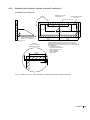
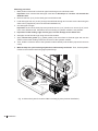
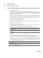
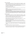
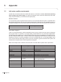
2577872 EN 1412 READ AND SAVE THESE INSTRUCTIONS INSTALLATION MANUAL Adiabatic air humidification/air cooling system Condair ME Control Humidification and Evaporative Cooling Thank you for choosing Condair Installation date (MM/DD/YYYY): Commissioning date (MM/DD/YYYY): Location ref.: Model: Serial number: Manufacturer Condair Plc Artex Avenue, Rustington, Littlehampton, West Sussex. BN16 3LN (UK) TEL: +44(0)1903 850 200 FAX: +44(0)1903 850 345 www.condair.co.uk Proprietary Notice This document and the information disclosed herein are proprietary data of Condair Plc. Neither this document, nor the information contained herein shall be reproduced, used, or disclosed to others without the written authorization of Condair Plc, except to the extent required for installation or maintenance of recipient's equipment. Liability Notice Condair Plc does not accept any liability due to incorrect installation or operation of the equipment or due to the use of parts/components/equipment that are not authorized by Condair Plc. Copyright Notice Copyright 2014, Condair Plc All rights reserved. Technical modifications reserved Contents 1 1.1 1.2 Introduction4 General 4 Notes on the installation manual 4 2 For your safety 6 3 3.1 3.2 3.3 3.4 Important notes on installation Delivery Storing/Transportation/Packaging Product designation / Which model do you have UL approved installation 8 8 8 9 9 4Installation 4.1 Installation overviews 4.1.1 Typical installation Condair ME Control (internal installation) 4.1.2 Typical installation Condair ME Control (external installation) 4.2 Mounting the evaporative module 4.2.1 Notes on positioning the evaporative module 4.2.2 Installation procedure evaporative module 4.3 Mounting the hydraulic module 4.3.1 Mounting the hydraulic module (internal installation) 4.3.2 Mounting the hydraulic module (external installation) 4.4 Water installation 4.4.1 Notes on water installation 4.4.2 Water installation (internal installation) 4.4.3 Water installation (external installation) 4.5 Mounting the control unit 4.5.1 Notes on positioning the control unit 4.5.2 Mounting the control unit 4.6 Electrical installation 4.6.1 Notes on electrical installation 4.6.2 Wiring diagram Condair ME Control 4.6.3 Installation work 10 10 10 11 12 12 14 24 24 25 27 27 29 30 31 31 32 33 33 35 37 5Appendix 5.1 Inlet water quality requirements 42 42 Contents 3 1 Introduction 1.1 General We thank you for having purchased the Condair ME Control Evaporative Humidifier and Cooler (Condair ME Control for short). The Condair ME Control incorporates the latest technical advances and meets all recognized safety standards. Nevertheless, improper use of the Condair ME Control may result in danger to the user or third parties and/or impairment of material assets. To ensure a safe, proper, and economical operation of the Condair ME Control, please observe and comply with all information and safety instructions contained in the present documentation as well as in the separate documentations of the components installed in the humidification system. If you have questions after reading this documentation, please contact your Condair representative. They will be glad to assist you. 1.2 Notes on the installation manual Limitation The subject of this installation manual is the Condair ME Control Evaporative Humidifier and Cooler. The various options and accessories are only described insofar as is necessary for proper operation of the equipment. Further information on options and accessories can be obtained in the respective instructions. This installation manual is restricted to the installation of the Condair ME Control and is meant for well trained personnel being sufficiently qualified for their respective work. Please note, some illustrations in this manual may show options and accessories which may not be supplied as standard or available in your country. Please check availability and specification details with your Condair representative. The installation manual is supplemented by various separate items of documentation (such as the operation manual), which are included in the delivery as well. Where necessary, appropriate cross-references are made to these publications in the installation manual. 4 Introduction Symbols used in this manual CAUTION! The catchword “CAUTION” used in conjunction with the caution symbol in the circle designates notes in this installation manual that, if neglected, may cause damage and/or malfunction of the unit or other material assets. WARNING! The catchword “WARNING” used in conjunction with the general caution symbol designates safety and danger notes in this installation manual that, if neglected, may cause injury to persons. DANGER! The catchword “DANGER” used in conjunction with the general caution symbol designates safety and danger notes in this installation manual that, if neglected, may lead to severe injury or even death of persons. Safekeeping Please safeguard this installation manual in a safe place, where it can be immediately accessed. If the equipment changes hands, the documentation must be passed on to the new operator. If the documentation gets mislaid, please contact your Condair representative. Language versions This installation manual is available in various languages. Please contact your Condair representative for information. Introduction 5 2 For your safety General Every person working with the Condair ME Control must have read and understood the installation manual and the operation manual of the Condair ME Control before carrying out any work. Knowing and understanding the contents of the installation manual and the operation manual is a basic requirement for protecting the personnel against any kind of danger, to prevent faulty operation, and to operate the unit safely and correctly. All ideograms, signs and markings applied to the unit must be observed and kept in readable state. Qualification of personnel All work described in this installation manual may only be carried out by specialists who are well trained and adequately qualified and are authorized by the customer. For safety and warranty reasons any action beyond the scope of this manual must be carried out only by qualified personnel authorised by the manufacturer. It is assumed that all persons working with the Condair ME Control are familiar and comply with the appropriate local regulations on work safety and the prevention of accidents. Intended use The Condair ME Control is intended exclusively for air humidification and air cooling in AHU's or air ducts within the specified operating conditions (see operation manual Condair ME Control). Any other type of application, without the written consent of the manufacturer, is considered as not conforming with the intended purpose and may lead to the Condair ME Control becoming dangerous. Operation of the equipment in the intended manner requires that all the information contained in this installation manual are observed (in particular the safety instructions). Danger that may arise from the Condair ME Control DANGER! Risk of electric shock! The Condair ME control unit (and the optional submerged UV system) contain live mains voltage. Live parts may be exposed when the control unit (or the terminal box of the optional submerged UV system) is open. Touching live parts may cause severe injury or danger to life. Prevention: The control unit must be connected to the mains only after all mounting and installation work has been completed, all installations have been checked for correct workmanship and the covers has been relocated properly. WARNING! Some type of evaporative material is manufactured from glass fibre. Though this material is not classified as hazardous, it is recommended that Personal Protection Equipment such as gloves, protective clothing and eye protection are used during handling to protect the user from fibres or dust. If dust is generated during handling it is recommended that respiratory protection is worn. 6 For your safety Correct lifting and handling Lifting or handling of components must only be carried out by trained and qualified personnel. Ensure that the lifting operation has been properly planned and risk assessed, and that all equipment has been checked by a skilled and competent Health & Safety representative. It is the customer's responsibility to ensure that operators are trained in handling heavy goods and to enforce the relevant lifting regulations. Preventing unsafe operation All persons working with the Condair ME Control are obliged to report any alterations to the unit that may affect safety to the owner without delay and to secure such systems against accidental power-up. Prohibited modifications to the unit No modifications must be undertaken on the Condair ME Control without the express written consent of the manufacturer. For the replacement of defective components use exclusively original accessories and spare parts available from your Condair representative. For your safety 7 3 Important notes on installation 3.1 Delivery After receiving: – Inspect shipping boxes for damage. Any damages to the shipping boxes must be reported to the shipping company. – Check packing slip to ensure all parts has been delivered. All material shortages are to be reported to your Condair representative within 48 hours after receipt of the goods. Condair assumes no responsibility for any material shortages beyond this period. – Unpack the parts/components and check for any damage. If parts/components are damaged, notify the shipping company immediately. – Check whether the components are suitable for installation on your site according to the product specification (refer to model key in the operation manual). 3.2 Storing/Transportation/Packaging Storing Until installation store the system components in its original packaging in a protected area meeting the following requirements: – Room temperature: 1 ... 40 °C – Room humidity: 10 ... 75 %rh Transportation For optimum protection always transport the unit in the original packaging and use an appropriate lifting/ transporting device. The packaged Condair ME unit may be carried by fork lift from the underside, but caution should be exercised to ensure that the load is balanced before lifting. Refer to the rating plate for weights and measures. WARNING! It is the customer's responsibility to ensure that operators are trained in handling heavy goods and to enforce the relevant lifting regulations. Packaging Keep the original packaging of the components for later use. In case you wish to dispose of the packaging, observe the local regulations on waste disposal. Please recycle packaging where possible. 8 Important notes on installation 3.3 Product designation / Which model do you have The product designation and the most important unit data are found on the rating plate fixed to the evaporative module and the control unit. Information regarding the rating plate and the product key can be found in the operation manual of the Condair ME Control. 3.4 UL approved installation In order to maintain a UL approved installation, the following installation requirements must be met, otherwise the Condair ME system will not be approved under UL998. 1. The Condair ME Control hydraulic unit must be installed external to the air stream in accordance with the typical installation drawing in chapter 4.1.2 – Typical installation Condair ME Control (external installation). 2. All interconnecting piping and connections between the evaporative module and the hydraulic unit, in direct contact with the air stream must be either copper or stainless steel. Note: water quality should be considered when selecting an appropriate material (i.e. copper is not suitable for RO water). 3. The Condair ME Control unit contains a large reservoir of water when in operation. Install the ME unit where is no risk of water damage, otherwise make provisions to contain any leakage. Important notes on installation 9 4 Installation 4.1 Installation overviews 4.1.1 Typical installation Condair ME Control (internal installation) Control unit 4 1 Electrical isolator Evaporative module Hydraulic module 2 5 Water supply line Air flow direction 3 Drain vent AHU drain Water drain line 1 - Mounting the evaporative module --> see chapter 4.2 – Mounting the evaporative module 2 - Mounting the hydraulic module --> see chapter 4.3 – Mounting the hydraulic module 3 - Water installation --> see chapter 4.4 – Water installation 4 - Mounting the control unit --> see chapter 4.5 – Mounting the control unit 5 - Electrical installation --> see chapter 4.6 – Electrical installation Fig. 1: Typical installation Condair ME Control (internal installation) 10 Installation 4.1.2 Typical installation Condair ME Control (external installation) Control unit 4 Electrical isolator 1 Evaporative module 5 Hydraulic module Water supply line 2 Pressure equalisation Air flow direction 3 AHU drain Drain vent Water drain line 1 - Mounting the evaporative module --> see chapter 4.2 – Mounting the evaporative module 2 - Mounting the hydraulic module --> see chapter 4.3 – Mounting the hydraulic module 3 - Water installation --> see chapter 4.4 – Water installation 4 - Mounting the control unit --> see chapter 4.5 – Mounting the control unit 5 - Electrical installation --> see chapter 4.6 – Electrical installation Fig. 2: Typical installation Condair ME Control (external installation) Installation 11 4.2 Mounting the evaporative module 4.2.1 Notes on positioning the evaporative module The design and dimensioning of the AHU/air duct as well as the location of the evaporative module inside the duct are determined, recorded and set compulsory when planning the entire system. Prior to installation, however, make sure the following criteria have been taken into consideration: – The AHU/air duct floor must be designed with a loading capacity capable of supporting the evaporative module’s weight. The weight of the evaporative module can be found on the rating plate. – In the area where the evaporative module is installed the floor of the AHU/air duct must offer a plane support (lengthwise and crosswise). – The evaporative module must be installed in a waterproof section of the AHU/air duct. – Downstream, directly after the evaporative module a drain pan with provision for running water to waste must be installed. The drain must be connected via a drain trap to the waste water line of the building. The drain trap must be sufficiently high and must be filled with water prior to commissioning, so that the drain trap is not emptied by the air pressure in the duct. The drain pan and the drain trap must be accessible for cleaning and disinfection as part of the periodic maintenance of the system. – For installation and maintenance sufficiently large access doors before and after the evaporative module must be available in the AHU/air duct. – The supply air must be filtered. We recommend to install an air filter with quality standard F7 (EU7) or better before the evaporative module. If no air filter or an air filter with lower quality is installed an increased maintenance will result. – An even air flow over the full cross section of the evaporative module must be guaranteed. If necessary, rectifiers or perforated plates must be installed. – The evaporative module must be positioned on upstands (supplied) to allow to install the drain pipe with a downslope through the side wall of the AHU/air duct. – In case of low ambient temperature the AHU/air duct must be insulated to prevent the moist air from condensing inside the duct. – If the AHU is equipped with a heater, make sure it is at least 600 mm (24") away from the evaporative module. – If the face velocity exceeds 3.5 m/s (689 fpm), the optional droplet separator cassettes must be installed. – Appropriate clearance must be available for the hydraulic module (and associated plumbing) when installing externally. 12 Installation – For inspection, commissioning and maintenance we recommend a minimum free space of 600 mm (24") before and after the evaporative module. Air flow direction a 395 mm / 15.6" Recommended service access Recommended service access 600 mm / 24" 600 mm / 24" (min. 200 mm / 7.9") Dimension “a”: ME Control (internal mounting): ME Control (external mounting): 272 mm (10.7") 111 mm (4.4") Fig. 3: Positioning of the evaporative module CAUTION! The ME unit contains a large reservoir of water when in operation. Install the ME unit where is no risk of water damage, otherwise make provisions to contain any leakage. Installation 13 4.2.2 Installation procedure evaporative module 1. Mounting the tank upstands to the tank: • Mounting the tank upstands supplied by Condair: fix tank upstands to the tank as shown in the figure below using the nuts (M8, AF: 13 mm) and washers supplied. Do not tighten the nuts. Fig. 4: Mounting the tank upstands to the tank 14 Installation 2. Mounting the tank: • Insert the tank into the AHU/air duct. WARNING! Use an appropriate lifting device or handle the tank with the help of another person to position it inside the duct. It is the customer's responsibility to ensure that operators are trained in handling heavy goods and to enforce the relevant lifting regulations. • Align the tank to the centre of the duct and perpendicular to the duct walls. When aligned fix tank upstands to the duct floor. CAUTION! The installer must take appropriate measures to ensure that the duct floor remains water proof once the tank upstands has been fixed to the duct floor. • Then, adjust the tank with the leveling nuts lengthwise and crosswise exactly horizontal using a level to. When adjusted, tighten the leveling nuts. = = Fig. 5: Mounting the tank Installation 15 3. Fix frame to the tank: • Fix the vertical supports to the tank using the nyloc nuts (M6, AF: 10 mm) and M6 washers. Then, align the vertical supports exactly vertical using a level and tighten the nuts. • Fix the cross member to the vertical supports using the nyloc nuts (M6, AF: 10 mm) and M6 washers. Then, tighten the nuts. Fig. 6: Fix frame to tank 16 Installation 4. Fix cross member of frame to AHU/duct ceiling: • Fix the cross member to the AHU/duct ceiling using appropriate fixings. Before tightening the screws align the vertical supports exactly vertical using a level. Fig. 7: Fix cross member to AHU/duct ceiling Installation 17 5. Mount the blanking plates on the air inlet side (blanking plates available as option): • Starting on each duct side on the bottom fix the side blanking plates to the duct wall using appropriate fixings. Before fixing make sure the side blanking plates are aligned exactly vertical and the free end of the blanking plates touches the middle of the corresponding vertical support. • Starting on one side fix the upper blanking plates to the duct ceiling using appropriate fixings. Before fixing make sure the upper blanking plates are aligned exactly perpendicular to the duct walls and the free ends of the blanking plates touch the cross member of the frame. • Starting on one side fix the lower blanking plates to the duct floor using welding studs, washers and nuts. Before fixing make sure the lower blanking plates are aligned exactly perpendicular to the duct walls and the free ends of the blanking plates touch the tank wall. CAUTION! The installer must take appropriate measures to ensure that the duct floor remains water proof once the lower blanking plates has been fixed to the duct floor. Fig. 8: Mount the Condair supplied blanking plates on the air inlet side 18 Installation 6. Mounting the cross bar: • Put the cross bar on the corresponding cross bar bracket with a distance of “A” to the vertical support (see table below). Type evaporative cassette (according to rating plate) Dimension A (nominal) F75 100 mm (4") F85 150 mm (6") F95 200 mm (8") P85 200 mm (8") P95 300 mm (12") A Note: On larger systems the supplied crossbar support(s) must be installed as shown to prevent bending of the cross bar! Fig. 9: Mounting the cross bar Installation 19 7. Mount optional submerged UV, if applicable: If your system is equipped with the submerged UV mount UV bulb assembly to the cross bar and the junction box to the tank in accordance with the separate manual for this option. 8. Mount distribution head assembly to the topmost evaporative cassettes: • This step must only be carried out on evaporative cassettes with glass fibre media: mount the appropriate distribution cassettes onto the corresponding evaporative cassettes. Then, fix the distribution cassettes to the evaporative cassettes using the plastic rivets supplied. • Mount the appropriate distribution heads onto the corresponding evaporative cassettes or distribution cassettes respectively. Then, fix the distribution heads to the evaporative cassettes or distribution cassettes respectively using the plastic rivets supplied. Evaporative cassettes with glass fibre Evaporative cassettes with polyester Fig. 10: Mount distribution head assembly to the topmost evaporative cassettes 20 Installation 9. Mount evaporative cassettes: Note: to avoid damage to the evaporative cassettes during transit, we recommend that the evaporative cassettes are fitted on site. • Before installing the evaporative cassettes sweep the interior of the tank. • Starting with the tallest evaporative cassettes on the bottom hook the cassettes into the vertical supports. Make sure the overlying cassettes slip properly into each other. 1 Fig. 11: Mount evaporative cassettes Installation 21 10.Mount the droplet separator cassettes (this step must only be carried out, if your system is equipped with a droplet separator): Note: to avoid damage to the droplet seperator cassettes during transit, we recommend that the droplet seperator cassettes are fitted on site. • Starting with the tallest droplet separator cassettes on the bottom, riveting the banks of the droplet separator cassettes together using ø 3.2 mm (0.13") blind rivets. Make sure the overlying cassettes slip properly into the subjacent cassettes. Fig. 12: Riveting the banks of the droplet separator cassettes together 22 Installation • Hook the lower separator brackets into the cross bar. • Then, starting on one side mount one separator bank after the other, align it and secure it with the upper separator brackets. Make sure separator metalwork slots into evaporator cassettes. Fig. 13: Mount the droplet separator banks Installation 23 4.3 Mounting the hydraulic module The mounting procedure of the hydraulic module depends on whether or not the hydraulic module is mounted internal or external to the duct. 4.3.1 Mounting the hydraulic module (internal installation) 1. Apply silicone free grease (e.g. gasket grease) onto the surface of the tank connector and onto the surface of the rubber sealing inside the connector of the hydraulic module. 2. Then, slide the connector bore of the hydraulic module carefully onto the tank connector until it comes to a stop. 3. With the help of a spirit level and the levelling feet on the bracket, align the hydraulic module exactly horizontal in both planes, i.e. front to back and left to right. Then, fix the hydraulic module to the tank using the bracket, nuts (M8, AF: 13 mm) and washers supplied and tighten the nuts. Fig. 14: Mounting the hydraulic module (internal installation) 24 Installation Mounting the hydraulic module (external installation) Clearances to be observed MINIMUM 25 mm (0.98") CLEARANCE TYP. DETAIL A HYDRAULIC MOUNTING BRACKET 150 mm (5.91") 156.83 mm (6.17") 110 mm (4.33") 110.5 mm (4.35") 173.17 mm (6.82") 110.5 mm (4.35") Ø80 mm (3.15") HOLE MINIMUM CLEARANCE OF 300 mm (11.81") REQUIRED 325 mm (12.80") 310 mm (12.20") AHU WALL WHEN PLANNING THE INSTALLATION OF A ME CONTROL SYSTEM (WITH EXTERNAL HYDRAULICS) THE CLEARANCE REQUIRED (OUTSIDE THE AHU) FOR THE FOLLOWING SHOULD BE CONSIDERED: • DISTRIBUTION HOSES • PRESSURE EQUALISATION • FEED THROUGH PLATES • INLET ASSEMBLY • DRAIN PLUMBING • DRAIN TRAP DETAIL A TYPICAL HYDRAULIC MOUNTING POSITION 127.5 mm (5.02") 8.5 mm (0.33") 10 mm (0.39") 10 mm (0.39") 4.3.2 Fig. 15: Clearances to be observed when mounting the hydraulic module externally Installation 25 Mounting procedure 1. Mark position of the hole for the drain pipe feed through on the AHU/duct wall. Important: when mounted the drain pipe must have a downslope of 1 to max. 2 % towards the AHU/duct wall. 2. Drill hole ø55 mm (2.2") for the drain pipe into AHU/duct wall. 3. Lead drain pipe ø54 mm (2.125") through the wall feed through and connect it to the tank using the elbow union (supplied as part of the external installation kit). 4. Cut drain pipe to length. Important: the end of the drain pipe must protrude 46 mm (1.81") minimum to 70 mm (2.75") maximum of the AHU/duct wall. Otherwise correct mounting of hydraulic module is not possible. 5. Important: De-bur leading edge of drain pipe, to avoid damage to the rubber seal. 6. Seal pipe around feed through using silicone-free sealant. 7. Apply silicone free grease (e.g. gasket grease) onto the surface of the drain pipe and onto the surface of the rubber sealing inside the connector of the hydraulic module. 8. Then, slide the connector bore of the hydraulic module carefully onto the drain pipe until it comes to a stop. 9. With the help of a spirit level align hydraulic module exactly horizontal. Then, fix the hydraulic module to the AHU/duct wall using appropriate fixings. mm 54 .1" 2 46 m 1.8 m " constant downslope 1 to max. 2% Fig. 16: Mount the hydraulic module of ME Circulating System (external installation) 26 Installation 4.4 Water installation 4.4.1 Notes on water installation The layout of the water piping (distribution, supply and drain water piping) depends on the system version. Refer to the corresponding chapter for detailed information and observe the following installation notes. – Notes on distribution piping – The distribution piping is to be carried out according to the figures found in chapter 4.4.2 – Water installation (internal installation) and 4.4.3 – Water installation (external installation) and the applicable local regulations for water installations. The indicated connection specifications and connection layout must be observed. – The distribution piping is made of ø15 mm (0.625") black plastic hoses (supplied as part of the internal installation kit) or stainless steel pipe (supplied as part of the external installation kit). – Make sure the distribution hoses have a constant downslope (no sagging) to the hydraulic module and are not kinked over the entire length. – All connections are made with push-fit fittings. – On systems where the hydraulic module is mounted outside the duct, the supplied feed throughs and hose supports must be used. General notes on installation of the hoses – Use the supplied black plastic hoses ø15 mm (0.625") only. For hygienic reasons do not use other hoses (except products supplied by your Condair distributor). – When cutting hoses use an appropriate cutting tool providing straight, kink-free cuts. CAUTION! After cutting the hoses any sharp edges must be deburred otherwise the couplings may be damaged. – The hoses must be free of kinks and other damage (longitudinal scratches or misshaped ends, in particular). – When cutting hoses always add at least 5 to 10 mm (0.2" to 0.4") to the required length. This way the hoses can be fastened correctly (down to the stop) to the push-fit couplings. – Make sure the hoses are not kinked and pay attention to the minimum bend radius of 100 mm (4"). – Do not lead hoses past hot system components (max. ambient temperature is 40 °C/104 °F). – After installation verify correct fastening of all hoses. Correctly mounted hoses can not be removed without pressing the locking ring. CAUTION! In order to avoid damage caused by leaking water during operation, all hoses must correctly be secured against accidently pulling out. Installation 27 – Notes on water supply – The water supply is to be carried out according to the figures found in chapter 4.4.2 – Water installation (internal installation) and 4.4.3 – Water installation (external installation) and the applicable local regulations for water installations. The indicated connection specifications must be observed. The installation material must be supplied by the customer. – The installation of a shut-off valve in the supply line is mandatory and should be made as close as possible to the hydraulic module. – Regarding supply water quality see appendix. – The installation material must be pressure-proof and certified for use in drinking water supply systems. – The wall feed through for the water supply must be done by the customer. Important: after installation the water supply pipe has to be sealed around the feed through using silicone-free sealant. – Important! To prevent new systems being contaminated with low quality water the entire water supply line must be flushed and tested until the supply water and the bacteria counts, are in line with the water quality specifications, before connecting it to the hydraulic module. For water quality requirements refer to chapter 5.1 – Inlet water quality requirements. – Notes on water drain – The water drain is to be carried out according to the figures found in chapter 4.4.2 – Water installation (internal installation) and 4.4.3 – Water installation (external installation) and the applicable local regulations for water installations. The indicated connection specifications must be observed. The installation material must be supplied by the customer. – Make sure the drain line is installed with a constant down-slope down to the tundish. – The drain pipe must not touch the tundish, allow air gap of min 20 mm (0.8"). – Make sure the drain pipe, the drain trap and the tundish are correctly fixed and easily accessible for inspections and cleaning purposes. – Access hole for the drain pipe through the duct/AHU must be provided by the customer. Important: after installation the drain pipe has to be sealed around the feed throughs using silicone-free sealant. – The minimum inside diameter of the drain pipe must be maintained throughout the entire length! – The drain pipe must be vented to the interior of the duct in accordance with the figures found in chapter 4.4.2 – Water installation (internal installation) and 4.4.3 – Water installation (external installation). – Notes on pressure equalisation for external mounted systems – The hydraulic module must be equipped with a pressure equalisation pipe connected to the interior of the duct to ensure the level in the hydraulic module corresponds with the level in the tank inside the duct (see figure in chapter 4.4.3 – Water installation (external installation). 28 Installation 4.4.2 Water installation (internal installation) Stages (box rows) Connection layout distribution hoses 2 1 2 1 3 2 1 3 4 2 1 3 4 2 1 3 4 2 1 3 5 4 2 1 3 5 4 2 1 3 5 2 4 5 Distribution hoses ø15 mm (0.625") constant slope (no sagging) 3 5 4 Water supply push-fit connector ø15 mm (0.625") 5 2...5 bar Feed throughs (supplied) Shut-off valve (supplied) Drain pipe ø28 mm (1.125") with constant downslope 1...2 % (not supplied) AHU drain with drain trap (not supplied) Drain trap height: Allow a height of 25 mm (1") for every 250 Pa of duct pressure (e.g. 100 mm (4") for 1000 Pa duct pressure). Drain pipe vent (mandatory, not supplied), highest point of vent tube must be above max. water level of tank Drain trap (not supplied) Drain trap height: Allow a height of 25 mm (1") for every 250 Pa of duct pressure (e.g. 100 mm (4") for 1000 Pa duct pressure) Open tundish (not supplied) Fig. 17: Water installation (internal installation) Installation 29 4.4.3 Water installation (external installation) Stages (box rows) Connection layout distribution hoses 2 1 2 1 3 2 1 3 4 2 1 3 4 2 1 3 4 2 1 3 5 4 2 1 3 5 Distribution hoses ø15 mm (0.625") constant slope (no sagging) 2 4 5 3 5 Feed through (supplied) 4 5 4 2 1 3 5 Pressure equalisation pipe (mandatory, not supplied) Shut-off valve (supplied) 2...5 bar Drain pipe vent (mandatory, not supplied), highest point of vent tube must be above max. water level of tank Water supply push-fit connector ø15 mm (0.625") Drain pipe ø28 mm (1.125") with constant downslope 1...2 % (not supplied) AHU drain with drain trap (not supplied) Drain trap height: Allow a height of 25 mm (1") for every 250 Pa of duct pressure (e.g. 100 mm (4") for 1000 Pa duct pressure). Drain trap (not supplied) Drain trap height: Allow a height of 25 mm (1") for every 250 Pa of duct pressure (e.g. 100 mm (4") for 1000 Pa duct pressure) Open tundish (not supplied) Important: the drain pipes must not touch the tundish - allow air gap of min 20 mm (0.8" ). Fig. 18: Water installation (external installation) 30 Installation 4.5 Mounting the control unit 4.5.1 Notes on positioning the control unit Please observe the following notes when positioning the Condair ME control unit: – The control unit can be mounted directly outside to the AHU/air duct or to a wall or stand (not supplied). – The control unit should ideally be positioned as close to the evaporative module as possible for ease of servicing and maintenance. Note: the hydraulic module of Condair ME Controls is equipped with a 5 m (16.4’) 14-core electrical inter-connecting cable for connection to the control unit. Make sure the control unit is mounted within the range of the inter-connecting cable. – The control unit is protected according to IP21. Make sure the control unit is installed in a drip-proof location and the admissible ambient conditions are complied with (see technical data in the operation manual to the Condair ME Control). – The power supply to the control unit must be equipped with an electrical isolator (not supplied) fitted within 1 m (39") for purposes of maintenance and emergencies. When positioning the control unit make sure the electrical isolator can be mounted within that range. Installation 31 4.5.2 Mounting the control unit 5 31 ") .4 2 (1 450 (17.7") 300 (11.8") .5 52 1") (2. 0 21 ) 3" (8. .5 52 ") 1 (2. 64.5 (2.5") Important: if multiple systems have been supplied to a site, ensure that the serial number on the control panel corresponds to the serial number marked on the evaporative module. Fig. 19: Mounting the control unit of Condair ME Controls Mounting procedure: 1. Mark the attachment points for the upper and lower wall support at the desired position with the help of a level. 2. Fix the wall supports to the wall using appropriate fixings. Before tightening the fixings adjust the wall supports horizontally using a level. 4. Unlock the screw of the front panel of the control unit, then remove the front panel. 5. Hang up the control unit onto the wall support and secure using the two M6 bolts in the top corners of the control unit. 6. Reattach the front panel and secure it with the screw. 32 Installation 4.6 Electrical installation 4.6.1 Notes on electrical installation DANGER! Risk of electric shock! The control unit contains live mains voltage. Live parts may be exposed when the control unit is open. Touching live parts may cause severe injury or danger to life. Prevention: The control unit must be isolated from the mains before commencing any installation work. WARNING! The electronic components inside the control unit are very sensitive to electrostatic discharge. Before carrying out installations work inside the control unit, appropriate measures must be taken to protect the electronic components against damage caused by electrostatic discharge (ESD protection). – All work concerning the electrical installation must be performed only by skilled and qualified technical personnel (e.g. electrician or technicians with appropriate training) authorised by the owner. It is the owner’s responsibility to verify proper qualification of the personnel. – The electrical installation must be carried out according to the wiring diagrams (see chapter 4.6.2 – Wiring diagram Condair ME Control), the notes on electric installation as well as the applicable local regulations. All information given in the wiring diagram must be followed and observed. – All cables must be lead into the control unit via the cable feed throughs on the bottom side of the control unit. The mains cable must be lead into the control unit via the cable opening equipped with the cable gland on the right side. Cable gland power supply Cable feed throughs control wiring Fig. 20: Cable feed throughs control units Installation 33 – All cables from the hydraulic module mounted inside the AHU/air duct must be lead via appropriate cable gland(s) out of the AHU/air duct. – Ensure cables are secured in such a way that the insulation is not damaged by sharp edges and so that they do not create a trip hazard. – Observe and maintain maximum cable length and required cross section per wire according to local regulations. – The mains supply voltage must match the respective voltage stated on the rating plate. 34 Installation D.PUMP D.LVL UV F3 PE L N 100...240 V/1~/50..60 Hz F4 SUPPLY L N N L1 S3 Q A A B B X5 T1 1 2 3 4 5 6 7 8 9 10 11 12 13 14 K2 X19 S1 PMC-24V100W1AA X4 T2 PMC-24V100W1AA B4 F2 (630 mAT) X12 X11 X3 X20 X10 X4 1 2 3 4 5 6 7 8 9 10 11 12 13 14 Fig. 21: Wiring diagram Condair ME Control B6 M1 U.V. L N N L1 H1 PE N/GND L/24V P F1 (1 AT) GND 24V P X9 T3 PMC-24V100W1AA B1 B2 B3 K1 X1 X2 SF J2 J3 min. °C B9 B5 24/10 V TMP HUM GND 24V E Enable J1 GND 24V IC D– D+ GND D– D+ GND 24V E 24V E GND GND A1 B8 B7 Y A2 3V LS2 CR2032 LS1 USB BAT SD Ethernet RJ45 24V+ GND – + GND – + GND – + GND J14 J12 J10 J6 J2 RS485 Control unit M L N 1 2 N L GND LEVEL/T PS3 PS2 PS1 24V P L PE N Service Running Unit On NF Y3 Y4 Y11 24V P SHIELD AIRT– AIRT+ X8 GND GND GND 24V 1 24V 2 24V 3 CS Cnd bn Cnd wh Tmp bk Tmp bu Shield SC1 SC2 PE PE PMP N PMP L PE UV– UV+ PE DOSP– DOSP+ Error 1 2 3 4 5 6 7 8 9 10 X7 JP5: 10V JP4: 24V GND PS4 PS5 24V P 5V P Y2 Y1 Y10 Y9 Y8 Y7 Y6 Y5 24V P ERR FQ N FQ1 N FQ2 GND FQ+ GND 24V P 24V P 24V SCA 24V SCB 24V E LVL DP 24V E CS1 24V E LEAK 24V E GND X13 X14 JP/TR X15.1 X15.2 X16 4.6.2 Wiring diagram Condair ME Control Installation 35 Legend wiring diagram Condair ME Control A1 Driver board A2 Control board B1 Ventilation interlock B2 Max. humidity monitor B3 Air flow monitor B4 Temperature and conductivity measuring B5 Sensor temperature and conductivity measuring B6 Level sensor dosing pump (option) B7 Demand or humidity/temperature signal B8 External On/Off switch (external enable) B9 Air temperature monitoring duct (option) BAT Backup battery (CR2032, 3V) CS Current sensor (UV lamp) D.LVL Terminal level switch dosing liquid tank D.PUMPTerminal dosing pump F1 Internal fuse mains supply (1 A slow acting) F2 Fuse 10/24 VDC supply(630 mA slow acting) F3 Internal fuse mains supply (6.3 A fast acting) F4 External fuse mains supply (10 A slow acting) H1 Remote operating and fault indication board (option) J1 Cable bridge if no external On/Off switch is connected J2 Cable bridge demand signal (for commissioning only) J3 Cable bridge if no safety chain is connected JP4 Jumper fitted= 24 V on X16 (JP5 removed) JP5 Jumper fitted= = 10 V on X16 (JP4 removed) JP/TR Jumper fitted on the last driver board K1 External safety chain K2 Cable harness from hydraulic module LS1 Leakage monitoring board (option) LS2 Sensor leakage monitoring (option) M1 Dosing pump (option) NF Mains filter Q Electrical isolator S1 Humidification On/Off switch S3 On/Off switch control unit SD Memory card SF Snap ferrite (wrap cable 3 times through ferrite) SUPPLYTerminal mains supply voltage T1..T3 24V power supply (T3 for systems with 4 or 5 stages only ) UV UV lamp (option) U.V. Terminal UV lamp X4 Terminal cable harness hydraulic module 36 Installation Installation work Note: for the connection of the available options please refer to the installation and operation manual of the corresponding option. Control signal (Y) Note: the control settings must be done via the control software of the Condair ME Control. Please refer to the operation manual of the Condair ME Control. 24 V TMP HUM GND 24V E Enable 24 V - voltage supply X16 JP5: 10V JP4: 24V External continuous humidity or temperature controller – rh 24 V Control unit P/PI B7 An external continuous humidity or temperature controller is to be connected to the contacts “HUM” (+) and “GND” (–) of the terminal block “X16” on the driver board in accordance with the wiring diagram. The admissible signal values can be found in the technical data table in the operation manual. The connecting cable must either be fed through the rectangular cable feed through or a free cable gland into the control unit. Note: If 24V supply is used for the external controller Jumper “JP4: 24V” must be set and Jumper “JP5: 10V” must be removed. The shielding of the control signal must be connected to terminal “GND”. Caution! If the shielding of the control signal is already connected to a potential or a grounded conductor, do not connect it to terminal “GND”. Humidity sensor 24/10V TMP HUM GND 24V E Enable 24 V - voltage supply X16 JP5: 10V JP4: 24V Control unit – rh 24 V 4.6.3 Y HUM B7 A humidity sensor is to be connected to the contacts “HUM” (+) and “GND” (–) of the terminal block “X16” on the driver board. The admissible signal values can be found in the technical data table in the operation manual. The connecting cable must either be fed through the rectangular cable feed through or a free cable gland into the control unit. Note: If 24V supply is used for the external controller Jumper “JP4: 24V” must be set and Jumper “JP5: 10V” must be removed. The shielding of the control signal must be connected to terminal “GND”. Caution! If the shielding of the control signal is already connected to a potential or a grounded conductor, do not connect it to terminal “GND”. Installation 37 24/10V TMP HUM GND 24V E Enable 24 V - voltage supply X16 JP5: 10V JP4: 24V Temperature sensor – T 24 V Control unit Y TEMP B7 A temperature sensor is to be connected to the contacts “TMP” (+) and “GND” (–) of the terminal block “X16” on the driver board. The admissible signal values can be found in the technical data table in the operation manual. The connecting cable must either be fed through the rectangular cable feed through or a free cable gland into the control unit. Note: If 24V supply is used for the external controller Jumper “JP4: 24V” must be set and Jumper “JP5: 10V” must be removed. The shielding of the control signal must be connected to terminal “GND”. Caution! If the shielding of the control signal is already connected to a potential or a grounded conductor, do not connect it to terminal “GND”. X16 JP5: 10V JP4: 24V 24 VDC On/Off humidistat A 24 VDC On/Off humidistat is to be connected to the contacts “24V” and “HUM” of the terminal block “X16” on the driver board. The connecting cable must either be fed through the rectangular cable feed through or a free cable gland into the control unit. 24/10V TMP HUM GND 24V E Enable Note: for the 24 VDC On/Off control jumper “JP5: 10V” must be removed and Jumper “JP4: 24V” must be set. Control unit ON/Off B7 38 Installation The shielding of the control signal must be connected to terminal “GND”. Caution! If the shielding of the control signal is already connected to a potential or a grounded conductor, do not connect it to terminal “GND”. External safety circuit To guarantee the safety of the humidification/cooling system, monitoring the operation by means of a safety circuit “K1” is an absolute requirement. X1 SC1 SC2 J2 Control unit K1 To accomplish this, the potential-free contacts of external monitoring devices (e.g. ventilation interlock “B1”, safety high limit humidistat “B2”, airflow monitor “B3”, etc.) are connected in series to the contacts “SC1” and “SC2” of the terminal block “X1” on the driver board in accordance with the wiring diagram. The connecting cable must either be fed through the rectangular cable feed through or a free cable gland into the control unit. If, for whatever reason, no external monitoring devices are connected, a cable bridge “J2” must be installed on the contacts “SC1” and “SC2” of the terminal block “X1”. B3 B2 Do not apply any extraneous voltage to contacts “SC1” and “SC2” via the contacts of the external monitoring devices. B1 The cross-section of the connecting cable must comply with the applicable local regulations (minimum 1 mm2). External enable X16 J1 The potential-free contact of an external enable switch is connected to the contacts “24 V E” and “Enable” of the terminal block “X16” on the driver board in accordance with the wiring diagram. The connecting cable must either be fed through the rectangular cable feed through or a free cable gland into the control unit 24/10V TMP HUM GND 24V E Enable If no external enable switch is connected, a cable bridge “J1” must be installed on the contacts “24V E” and “Enable” of the terminal block “X16”. Control unit S2 CAUTION! Do not apply any extraneous voltage to terminals via the enable switch. Installation 39 Connecting the 14-core inter-connecting cable from the hydraulic module 1 2 3 4 5 6 7 8 9 10 11 12 13 14 X4 Level Sensor 1 GND Pumps 4&5, Drain & Sensor GND Pumps 1,2&3 VCC Pumps 1,2&3 VCC Pumps 4&5 Signal Pump 4 Signal Pump 2 Signal Pump 1 Signal Pump 3 Signal Pump 5 Signal Drain Pump VCC Drain&Inlet Valve GND Drain Valve GND Inlet Valve 1 2 3 4 5 6 7 8 9 10 11 12 13 14 The 14-core inter-connecting cable “K2” from the hydraulic module is to be connected according to the wiring diagram to the terminals “X4”. The 14-core interconnecting cable must be fed through the rectangular cable feed through into the control unit. Note: The 5 m inter-connecting cable has to be cut to length on site. Control unit K2 Connecting the remote operating and fault indication (option) H1 Error Service Running Unit On 1 2 3 4 5 6 7 8 9 10 Control unit The optional remote operating and fault indication board contains four potential-free relay contacts for the connection of the following operating and fault indications: – “Error”: This relay is activated if an error is present. – “Service”: This relay is activated when the set service interval has expired. – “Running” (Humidification/Cooling): This relay closes as soon as the Condair ME is humidifying/cooling. – “Unit on”: This relay closes as soon as the voltage supply to the control unit of the Condair ME is switched on. The connecting cable must either be fed through the rectangular cable feed through or a free cable gland into the control unit. The maximum contact loading is 250V/8A. Appropriate suppressor modules are to be used for the switching of relays and miniature contactors. 40 Installation Mains voltage supply CAUTION! Before connecting the mains voltage supply, make sure the voltage indicated on the rating plate meets the local line voltage. Otherwise, do not connect the control unit. F3 L N SUPPLY Control unit F4 PE L N 100...240 V/1~/50..60 Hz Q Connect mains voltage supply 100...240 V/1~/50...60 Hz in accordance with the wiring diagram, to the terminal block “SUPPLY” in the control unit. The mains supply cable must be led into the control unit via the cable gland on right side on the bottom of the control unit. The installation of the fuse F4, the electrical isolator “Q” (all pole disconnecting device with a minimum contact clearance of 3 mm/0.12") and a fault current protection switch with 30 mA trigger current (by client) in the mains supply line are mandatory. The electrical isolator must be mounted in direct proximity of the control unit (max. distance 50 cm/19.69") and must be easily accessible in a height between 0.6 m/23.62" and 1.9 m/74.8" (recommended: 1.7 m/66.93"). The cross-section of the mains cable must comply with the applicable local regulations (min. 1.5 mm2/0.0023 sq.in.). Installation 41 5 Appendix 5.1 Inlet water quality requirements Condair Plc recommends that the Condair ME must be connected to a clean, wholesome (drinking water quality) mains water supply. For areas of hard water and to minimise scale build up the water supply may be treated by a reverse osmosis system (RO). Reverse Osmosis For Condair ME systems supplied with RO water it is recommended that the system is operated within the following parameters. The use of RO water fed tanks and reservoirs is only permitted as part of a managed and hygiene monitored water system and should form part of the water system risk assessment. System Conductivity Condair ME Control > 5 μS cm-1 at 20 °C (68 °F) Other Water Supplies There is a growing demand to utilise sustainable water sources to help overcome scarcity challenges and recycle water. It is possible to use high-quality, treated effluent for non-wholesome applications. The following gives guidance on reclaimed water quality that may be acceptable for use within the Condair ME. “Effluent treated water”, must be treated by an appropriate water treatment method and risk assessed to ensure it is safe and suitable for use in the Condair ME unit. It is the responsibility of the user to ensure that the water supply system is part of a managed, hygiene monitored water system, risk assessed and complies with the local regulations and bylaws. Below are example water conditions that would allow a Condair ME to operate within specification. 42 Appendix Parameter Content in supply water Concern Temperature < 20 °C (68 °F) Warm water favours growth of bacteria Aluminium Ammonium Calcium Chloride Colour Copper Conductivity pH < 0.50 mg/l < 300 mg/l < 300 mg/l None < 1 mg/l < 650 μS cm-1 at 20°C (68 °F) 6.5 to 9.5 Iron < 0.5 mg/l Manganese < 0.1 mg/l No specific concerns Odour passed to air Scale formation Corrosion of stainless steel Not directly a concern Deposits and corrosion stimulation Total hardness and scale formation. Acid or Alkali damage to equipment. Deposit formation on oxidation and a critical support role in Legionella growth. Deposit formation Nitrate - No specific concerns Nitrite - No specific concerns Odour Acceptable to users Smell passed to air Sulphate < 250 mg/l No specific comments Parameter Content in supply water Concern Sodium - No specific concerns Total organic carbon - No specific concerns Turbidity < 5 NTU No specific concerns Colony count 22°C < 1000 cfu/ml Indicator of contaminated water supply Coliform bacteria < 10 cfu/100 ml Indicator of poor water quality Legionella bacteria < 50 cfu/1000 ml Risk of Legionella Pseudomonas species < 10 cfu/100 ml Indicator of slime forming potential Controlled Substances DANGER! Many of the following controlled substances are toxic; for example vinyl chloride is highly toxic, flammable and carcinogenic and could be evaporated off the matrix and passed to the airflow. Therefore it is important to note that any supply water coming from complex waste water, which may contain these contaminates should therefore be carefully risk assessed by a water treatment specialist. Controlled substances Clostridium perfringens (including spores) Acrylamide Antimony Arsenic Benzene Benzo(a)pyrene Boron Bromate Cadium Chromium Cyanide 1,2-dichloroethane Epichlorohydrin Fluoride Lead Mercury Nickel Pesticides Polycyclic aromatic hydrocarbons Selenium Tetrachloroethene and Trichloroethene Trihalomethanes Vinyl chloride Water Monitoring The Condair ME water system must be monitored for hygiene as part of the maintenance programme. Appendix 43 CONSULTING, SALES AND SERVICE: Condair Plc Artex Avenue, Rustington, Littlehampton, West Sussex. BN16 3LN (UK) TEL: +44(0)1903 850 200 FAX: +44(0)1903 850 345 www.condair.co.uk