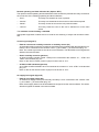
1
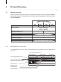
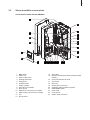
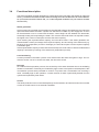
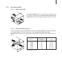
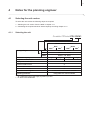
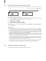
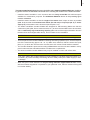
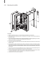
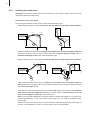
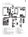
Condair CP3mini Electrode Humidifiers 2549073 EN 0909 Mounting instructions Contents 1 1.1 1.2 Introduction To the very beginning Notes on the mounting instructions 4 4 4 2 For your safety 6 3 3.1 3.2 3.3 3.4 3.5 3.6 3.7 3.7.1 3.7.2 3.8 3.9 Product Overview Models overview Identification of the unit Steam humidifier construction Functional description Humidification system overview Options Accessories Accessories overview Accessory details Standard delivery Storing/Transportation/Packaging 8 8 8 9 11 12 14 14 14 15 16 16 4 4.1 4.1.1 4.1.2 4.2 4.3 Notes for the planning engineer Selecting the unit version Selecting the unit Calculating the maximum required steam capacity Selecting the options an accessories Selecting the control system 17 17 17 18 18 19 5 5.1 5.2 5.2.1 5.2.2 5.2.3 5.3 5.3.1 5.3.2 5.3.3 5.3.4 5.3.5 5.3.6 5.4 5.4.1 5.4.2 5.4.3 5.5 5.5.1 5.5.2 5.5.3 5.5.4 Mounting and installation work Important notes for mounting and installation work Mounting the unit Notes on locating and mounting the unit Mounting the humidifier Inspecting the installed unit Steam installation Overview steam installation Positioning and mounting of the steam distribution pipe Installing the steam distributors Installing the steam hose Installing the condensate hose Inspecting the steam installation Water installation Overview water installation Notes on water installation Inspecting the water installation Electric installation Wiring diagram Condair CP3mini Notes on electric installation Inserting the CF card Inspecting the electrical installation 21 21 22 22 24 25 26 26 27 29 30 31 32 33 33 33 34 35 35 36 38 38 6 6.1 6.2 6.3 Product specifications Technical data Unit dimensions Declaration of conformity 39 39 40 41 1 Introduction 1.1 To the very beginning We thank you for having purchased the steam humidifier Condair CP3mini. The steam humidifier Condair CP3mini incorporates the latest technical advances and meets all recognized safety standards. Nevertheless, improper use of the Condair CP3mini may result in danger to the user or third parties and/or impairment of material assets. To ensure a safe, proper, and economical operation of the steam humidifier Condair CP3mini, please observe and comply with all information and safety instructions contained in the present manual as well as the instructions given in the manuals for the components used in the humidification system. If you have questions, which are not or insufficiently answered in this documentation, please contact your Condair supplier. They will be glad to assist you. 1.2 Notes on the mounting instructions Limitation The subject of these mounting instructions is the steam humidifier Condair CP3mini in its different versions. The various accessories are only described insofar as this is necessary for proper operation of the equipment. Further information on accessories can be obtained in the respective instructions. These mounting instructions is restricted to the installation of the steam humidifier Condair CP3mini and is meant for well trained personnel being sufficiently qualified for their respective work. The mounting instructions are supplemented by various separate items of documentation (operating instructions, spare parts list, manuals for accessories, etc.). Where necessary, appropriate crossreferences are made to these publications in the mounting instructions. Symbols used in this manual CAUTION! The catchword “CAUTION” designates notes in this documentation that, if neglected, may cause damage and/or malfunction of the unit or other material assets. WARNING! The catchword “WARNING” used in conjunction with the general caution symbol designates safety and danger notes in this documentation that, if neglected, may cause to injury to persons. DANGER! The catchword “DANGER” used in conjunction with the general caution symbol designates safety and danger notes in this documentation that, if neglected, may lead to severe injury or even death of persons. Safekeeping Please safeguard these mounting instructions in a safe place, where it can be immediately accessed. If the equipment changes hands, the documentation should be passed on to the new operator. If the documentation gets mislaid, please contact your Condair supplier. Language versions These mounting instructions is available in various languages. Please contact your Condair supplier for information. Copyright protection The present mounting instructions are protected under the Copyright Act. Passing-on and reproduction of the manual (or part thereof) as well as exploitation and communication of the contents are prohibited without written permission by the manufacturer. Violation of copyright terms is subject to legal prosecution and arises liability for indemnification. The manufacturer reserves the right to fully exploit commercial patent rights. 2 For your safety General Every person working with the Condair CP3mini must have read and understood the mounting instructions before carrying out any installation work. Knowing and understanding the contents of the mounting instructions is a basic requirement for protecting the personnel against any kind of danger, to prevent faulty installation, and to install and operate the unit safely and correctly. All ideograms, signs and markings applied to the unit must be observed and kept in readable state. Qualification of personnel All actions described in the present mounting instructions must be carried out only by well trained and sufficiently qualified personnel authorised by the owner. For safety and warranty reasons any action beyond the scope of this manuals must be carried out only by qualified personnel authorised by the manufacturer. It is assumed that all persons working with the Condair CP3mini are familiar and comply with the appropriate regulations on work safety and the prevention of accidents. Intended use The steam humidifier Condair CP3mini is intended exclusively for air humidification via a steam distributor approved by the manufacturer (unit versions Condair CP3mini PD..) or via the integrated ventilation unit (unit versions Condair CP3mini PR..) within the specified operating conditions (see chapter 6 “Product specifications”). Any other type of application without the express written consent of the manufacturer is considered as not conforming with the intended purpose and may lead to the Condair CP3mini becoming dangerous. Operation of the equipment in the intended manner requires that all the information in these instructions is observed (in particular the safety instructions). Danger that may arise from the unit: The Condair CP3mini is mains powered. DANGER! One may get in touch with live parts when the unit is open. Touching live parts may cause severe injury or danger to life. Prevention: The steam humidifier must be connected to the mains only after all mounting and installation work has been completed and the cover has been relocated properly. Behaviour in case of danger All persons working with the Condair CP3mini are obliged to report any alterations to the unit that may affect safety to the owner without delay and to secure such a unit against accidental power-up. Prohibited modifications to the unit No modifications must be undertaken on the Condair CP3mini without the express written consent of the manufacturer. For the replacement of defective components use exclusively original accessories and spare parts available from your Condair supplier. 3 Product Overview 3.1 Models overview Steam air humidifiers Condair CP3mini are available in the two basic versions for duct air humidification and direct room air humidification with different heating voltages and steam capacities of 2 kg/h and 4 kg/h. Model Condair CP3mini Duct Max. steam capacity PD2 PD4 PR2 PR4 2 kg/h 4 kg/h 2 kg/h 4 kg/h Heating voltages 230V1~ / 50..60Hz 240V1~ / 50..60Hz 200V2~ / 50..60Hz Integrated ventilation unit ––– X Display and control unit X External On/Off control X External P/PI control X Internal P/PI controller X Admissible control signals 0-10V, 0-5V, 1-5V, 0-20mA, 4-20mA Operating parameter 3.2 Room configurable via control software Identification of the unit The identification of the unit is found on the type plate (for the location of the type plate see unit overview): Total steam capacity in kg/h Type designation Unit voltage (heating voltage) Maximum steam capacity Admissible water supply pressure Approval marks Electrical power Control voltage Type of protection Serial number Month/Year Walter Meier (Klima International) AG CH-8808 Pfäffikon Type: Condair CP3mini PD4 Voltage h: 230V1~ / 50..60Hz Steam capacity: 4.0 kg/h Water pressure: 1...10 bar XXXXXXX 06.09 el. power: 3.1kW / 13.5A ctrl. voltage: 230V1~ / 50..60Hz Protection: IP20 Made in Switzerland 3.3 Steam humidifier construction Construction Condair CP3mini PD2/PD4 24 1 2 23 3 22 4 5 21 6 7 8 19 9 20 18 1 2 3 4 5 6 7 8 9 10 11 12 13 Back panel Water cup Water supply hose Heating electrodes Filling hose Overflow hose Steam cylinder Inlet valve (not visible) Drain pump Water drain connector (not visible) Water supply connector (not visible) Tub Driver board 17 16 15 14 13 12 11 10 14 Type plate 15 Remote operating and fault indication board (Option) 16 Control board with CF card 17 Unit switch 18 Drain key 19 Display and control unit 20 Operation status indicators (LED's) 21 Intermediate panel 22 Front cover 23 Level sensor 24 Steam outlet connector 10 Construction Condair CP3mini PR2/PR4 25 1 24 2 23 3 22 4 5 21 6 7 8 19 9 20 18 1 2 3 4 5 6 7 8 9 10 11 12 13 17 Back panel Water cup Water supply hose Heating electrodes Filling hose Overflow hose Steam cylinder Inlet valve (not visible) Drain pump Water drain connector (not visible) Water supply connector (not visible) Tub Driver board 16 15 14 13 12 11 10 14 Type plate 15 Remote operating and fault indication board (Option) 16 Control board with CF card 17 Unit switch 18 Drain key 19 Display and control unit 20 Operation status indicators (LED's) 21 Unit intermediate panel 22 Front cover 23 Level sensor 24 Condensate hose 25 Ventilation unit 11 3.4 Functional description The steam humidifier Condair CP3mini is a pressureless steam generator that utilizes an electrode heating. The steam humidifier Condair CP3mini is designed for air humidification via a steam distributor (unit versions Condair CP3mini PD..) or via the integrated ventilation unit (unit versions Condair CP3mini PR..). Steam generation Any time steam is requested, the electrodes are supplied with voltage. Simultaneously, the inlet valve opens and water enters the steam cylinder from the bottom via water cup and supply line. As soon as the electrodes come in contact with the water, current begins to flow between the electrodes, eventually heating and evaporating the water. The more the electrode surface is exposed to water, the higher is the current consumption and thus the steam capacity. Upon reaching the requested steam capacity, the inlet valve closes. If the steam generation decreases below a certain percentage of the required capacity, due to lowering of the water level (e.g. because of the evaporation process or drainage), the inlet valve opens until the required capacity is available again. If the required steam capacity is lower than the actual output, the inlet valve is closed until the desired capacity is achieved by lowering of the water level (evaporation process). Level monitoring A sensor provided in the steam cylinder cover detects when the water level gets too high. The moment the sensor comes in contact with water, the inlet valve closes. Drainage As a result of the evaporation process, the conductivity of the water increases due to an escalating mineral concentration. Eventually, an inadmissibly high current consumption would take place if this concentration process were permitted to continue. To prevent this concentration from reaching a value, unsuitably high for the operation, a certain amount of water is periodically drained from the cylinder and replaced by fresh water. Control The steam production can be controlled steplessly via the internal or an external continuous controller or with an On/Off control via an external humidistat. 12 Humidification system overview System overview Condair CP3mini PD2/PD4 41-.. min. 5 % – 10 13 30 Øm in. in . Rm 200 mm DS22 12 m 0m 1 KS10 300 m m min. 20 % + W21 Pmax. 800 Pa Pmin. -800 Pa min. 10 % – 11 Rmin. min. 300 mm 41-.. 12 min. 5 % – 13 W21 mm Pmax. 800 Pa Pmin. -800 Pa min. 10 % – Øm in. 200 2 KS10 G 3/4" 3 11 ø22 mm 4 9 Z261 5 min. 50 cm 3.5 G 1/2" min. 10 % – 6 8 ø10/8 mm DS22 7 125...1250µS/cm 1...10 bar 1...40 °C ≥ 40 mm min. 10 % – 1 2 3 4 5 6 7 Steam humidifier Steam connector Water supply connector Water drain connector Filter valve (accessory “Z261”) Manometer (installation recommended) Funnel with siphon (building side) 8 9 10 11 12 13 Water drain hose (accessory “DS22”) Connecting cables Steam hose (accessory “DS22”) Condensate hose (accessory “KS10”) Steam distribution pipe (accessory “41-...”) Steam nozzle (accessory “W21”) 13 System overview Condair CP3mini PR2/PR4 1 2 G 3/4" 3 ø22 mm 4 Z261 5 6 min. 50 cm 9 G 1/2" min. 10 % – ø10/8 mm 8 DS22 7 125...1250µS/cm 1...10 bar 1...40 °C ≥ 40 mm min. 10 % – 1 2 3 4 5 Steam humidifier Ventilation unit Water supply connector Water drain connector Filter valve (accessory “Z261”) 6 7 8 9 Manometer (installation recommended) Funnel with siphon (building side) Water drain hose (accessory “DS22”) Connecting cables 14 3.6 Options Condair CP3mini PD2 PD4 PR2 Cable glands set with counter nuts – 1x M20 for cable diameters from 7.0 to 13.0 mm – 1x M16 for cable diameters from 4.5 to 10.0 mm – 1x M12 for cable diameters from 2.5 to 6.5 mm 1x CG Radio humidity sensor Radio humidity sensor set consisting of radio humidity sensor and receiver board for the humidity control via the internal P/PI humidity controller. The maximum range of the radio humidity sensor in an open room is 25 m Note: the radio humidity sensor as well as the receiver board must be installed and configured only by a service technician of your Condair representative. 1x RH Water drain hose Water drain hose to lead the drain line through the back panel of the unit. 1x WDH Remote operating and fault indication PCB with relay contacts for the connection of remote displays for “Operation”, “Steam”, “Fault” and “Service”. 1x RFI 3.7 Accessories 3.7.1 Accessories overview PR4 Accessories for water installation Condair CP3mini PD2 PD4 Filter valve PR2 PR4 1x Z261 Accessories for steam installation Condair CP3mini PD2 PD4 PR2 PR4 Steam nozzle (Details see chapter 3.7.2.1) 1x W21 ––– Steam distribution pipe (Details see chapter 3.7.2.2) 1x 41-... ––– Steam hose / meter 1x DS22 ––– Condensate hose / meter 1x KS10 Accessories for humidity control Condair CP3mini PD2 PD4 PR2 PR4 Humidity sensor for duct installation EGH110 ––– Humidity sensor for room installation ––– EGH130 Duct humidistat HBC ––– Room humidistat ––– HSC 15 3.7.2 Accessory details 3.7.2.1 Steam nozzle W21 The steam nozzle W21 can be mounted in the ventilation duct horizontally or vertically. Keep a minimum distance clearance (A) of 200 mm between nozzle opening and the opposite duct wall. 3.7.2.2 Steam distribution pipe 41-... The steam distribution pipes are selected on the basis of the duct width (for horizontal installation) or the duct height (for vertical installation) and the capacity of the steam humidifier. Important! Always select the longest possible steam distribution pipe (optimum humidification distance). Steam distribution pipes Type 41-... 1) Length (L) steam distribution pipe in mm 2) Duct width (B) 41-200 41-350 41-500 41-650 41-800 41-1000 41-1200 200 350 500 650 800 1000 1200 210...400 400...600 550...750 700...900 900...1100 1100...1300 1300...1600 1) 2) Material: CrNi steel special length on request in mm 16 3.8 Standard delivery The standard delivery includes: – Steam humidifier Condair CP3mini equipped with the options ordered according to chapter 3.6, fixing set, mounting instructions (this document) and operating instructions, packaged in cardboard box (351 mm x 263 mm x 729 mm, shipping weight: 7.4 kg) – Ordered accessories with operating instructions according chapter 3.7, packed separately – Spare parts list 3.9 Storing/Transportation/Packaging Storing Store the unit in a protected area meeting the following requirements: – Room temperature: 1 ... 40 °C – Room humidity: 10 ... 75 %rh Transportation For optimum protection always transport the unit in the original packaging. Always place the unit on its back side. Packaging Keep the original packaging of the Condair CP3mini for later use. In case you wish to dispose of the packaging, observe the local regulations on waste disposal. Never dispose of the packaging to the environment. 17 4 Notes for the planning engineer 4.1 Selecting the unit version To select the unit version the following steps are required: 1. Selecting the unit version from the table in chapter 4.1.1 2. Calculating the required maximum steam capacity according chapter 4.1.2 4.1.1 Selecting the unit Condair CP3mini PD4 230V1 Model Condair CP3mini Duct PD2 Heating voltages Max. steam capacity 240V1 240V1~ / 50..60Hz 200V2 200V2~ / 50..60Hz 2 kg/h 4 kg/h PR4 2) 2) 230V1~ / 50..60Hz 2 kg/h ––– 4 kg/h X Display and control unit X External On/Off control X External P/PI control X Internal P/PI controller X Admissible control signals 0-10V, 0-5V, 1-5V, 0-20mA, 4-20mA Operating parameter 2) PR2 1) 230V1 Integrated ventilation unit 1) Room PD4 1) Air conditioning systems with supply air portion up to 66% for direct room humidification configurable via control software 18 4.1.2 Calculating the maximum required steam capacity The maximum required steam capacity must be calculated based on one of the following formulas: Condair CP3mini PD4 230V1 mD = V • ρ 1000 • (x2 - x1) or V mD = 1000 • ε • (x2 - x1) mD: maximum steam demand in kg/h V: volume of supply air portion per hour in m3/h (for indirect room humidification) or room volume to be humidified per hour in m3/h (for direct room humidification) ρ: specific gravity of air in kg/m3 ε: specific volume of air in m3/kg x2: desired absolute room air humidity in g/kg x1: minimum absolute supply air humidity in g/kg The values for ρ, ε, x2 and x1 can be gathered from the h,x-diagram or the Carrier-Diagram for moist air respectively. Important notes: – The required maximum steam capacity depends on the specific application and the installation. The calculated steam capacity based on the above formulas, the h,x diagram and the condition of the air to be humidified does not consider any steam loss (e.g. due to condensation in the steam hoses and the steam distributors), any heat loss of the unit as well as any absorption or release of humidity of materials located in the room being humidified. In addition, the calculated steam capacity does not consider any losses caused by the draining rate depending on the water quality as well as any losses occur if the steam humidifier is operated on a mains circuit with a ground fault circuit interrupter. The total amount of losses depends on the entire system and must be taken into consideration when calculating the required steam capacity. If you have any questions regarding the calculation of the steam capacity please contact your Condair supplier. – For systems where the max. required steam capacity varies extensively (e.g. for test facilities or for systems with variable air volume flow, etc.), please contact your Condair supplier. 4.2 Selecting the options an accessories For selecting the options and accessories see chapter 3.6 and 3.7. 19 4.3 Selecting the control system The steam humidifiers Condair CP3mini are designed to be controlled with On/Off control via an external humidistat or with continuous control via an external P/PI humidity controller or the internal P/PI humidity controller. – System 1: Room humidity control System 1 is suited for direct room humidification and air conditioning systems with mainly recirculated air. The humidity sensor or humidistat respectively is preferably located in the room itself or in the exhaust air duct. A1 B1 B2 B3 B4 PII PIE Y humidity sensor ventilation interlock airflow monitor safety humidistat humidistat internal P/PI controller external continuous controller (e.g. PI controller) input signal from A1 Condair CP3mini PD.. Condair CP3mini PR... A1 B1 B2 B3 B4 PII PIE Y humidity sensor ventilation interlock airflow monitor safety humidistat humidistat internal P/PI controller external continuous controller (e.g. PI controller) input signal from A1 20 – System 2: Room humidity control with continuous limitation of the supply air humidity System 2 is suited for air conditioning systems with a large portion of supply air, low supply air temperature, post-humidification, or variable airflow volume. If the supply air humidity exceeds the preset value, the continuous limitation is effected prior to the room humidity control. The humidity sensor (A1) is preferably located in the exhaust air duct or in the room itself. The humidity sensor (A2) for the limitation of the supply air humidity is located in the supply air duct after the steam distribution pipe. This control system requires a continuous controller with the option to connect a second humidity sensor. Attention! The continuous limitation of the supply air humidity is no substitute for the safety humi distat. A1/2 humidity sensor B1 ventilation interlock B2 airflow monitor B3 safety humidistat PII Internal P/PI controller PIE External continuous controller (e.g. PI controller) Y input signal from A1 Z input signal from A2 Condair CP3mini PD.. Condair CP3mini PR... A1/2 humidity sensor B1 ventilation interlock B2 airflow monitor B3 safety humidistat PII Internal P/PI controller PIE External continuous controller (e.g. PI controller) Y input signal from A1 Z input signal from A2 Please contact your Condair supplier, if your application meets the following conditions: – Humidification of small rooms up to 200 m3 – Air conditioning systems with a high number of air exchanges – Systems with variable air volume flow – Test facilities with extreme control accuracy requirements – Rooms with a high variation in max. steam capacity – Systems with temperature fluctuations – Cold rooms and systems with dehumidification 21 5 Mounting and installation work 5.1 Important notes for mounting and installation work Qualification of personnel All mounting and installation work must be carried out only by well qualified personnel authorised by the owner. It is the owner’s responsibility to verify proper qualification of the personnel. General note Strictly observe and comply with all information given in the present mounting instructions regarding the location of the unit and the installation of water, steam and electricity. Observe and comply with all local regulations dealing with water, steam and electrical installations. Safety Some installation work requires removal of the unit cover. Please note the following: DANGER! Danger of electrical shock! You may get in touch with live parts when the unit is open. The steam humidifier must be connected to the mains only after all mounting and installation work has been completed and the cover has been relocated properly. CAUTION! The electronic components inside the humidifier are very sensitive to electrostatic discharge. When the unit is open for installation work, appropriate measures must be taken to protect these components against damage caused by electrostatic discharge (ESD protection). 22 5.2 Mounting the unit 5.2.1 Notes on locating and mounting the unit 250 . min mm min. 500 mm Condair CP3mini PR.. . 25 min min. 2 m mm mm 650 mm 265 175 Note: The minimum spaces apply for a room atmosphere of 15 °C and max. 60 %rh. For lower temperatures and/or higher humidity the values should be adjusted accordingly m 0m 2 11. Note: In order to achieve a uniform distribution of the humidity within the room, additional factors such as the room size, the room height, etc., must be taken into consideration besides observing the minimum distances. If you have questions concerning the direct room humidification, please contact your Condair supplier. kg Condair CP3mini PD.. mm min .2 m 5m 26 175 mm 650 mm mm min. 400 mm 250 min . 60 min. 600 mm . min 50 .2 min 2 11. kg 0m m m 23 To ensure proper functioning of the steam humidifier and to obtain an optimal efficiency, the following points must be considered and observed when choosing the location for the steam humidifier: – Install the steam humidifier in such a manner that it is freely accessible with sufficient space available for maintenance purposes. The minimum distances shown in the preceding figure must be maintained. – Install the steam humidifier so that the length of the steam hose is kept as short as possible (max. 4 m) and that the minimum bend radius (R= 300 mm) and up-slope (20 %) or downslope (5 %) of the steam hose is observed (see chapter 5.3.4). – The steam humidifiers Condair CP3mini are designed for wall-mounting. Make sure that the construction (wall, pillar, floor-mounted console, etc.) to which the humidifiers are to be mounted, offers a sufficiently high load-bearing capacity (take notice of the weight information found in the dimension sand weights table above), and is suitable for the installation. CAUTION! Do not mount the steam humidifier directly to the ventilation duct (insufficient stability). – The back panel of the Condair CP3mini is retaining heat during operation (max. surface temperature of the metal housing approx. 60 - 70 °C). Make sure, therefore, that the construction (wall, pillar, etc.) to which the units are to be mounted, does not consist of heat-sensitive material. – The Condair CP3mini is protected according to IP20. Make sure the units are installed in a dripproof location and the admissible ambient conditions are complied with. – The steam humidifier Condair CP3mini may only be installed in rooms with a floor drain. CAUTION! If for some reason the Condair CP3mini must be installed in a location without floor drain, it is mandatory to provide a leakage monitoring device to safely interrupt the water supply in case of leakage. – When fixing the Condair CP3mini use only the fixing materials supplied with the unit. If fixing with the materials supplied is not possible in your particular case, select a method of fixing that is of similar stability. 24 Mounting the humidifier 120 mm A B B 33 mm A 420 mm 5.2.2 A C 132 mm 132 mm D Procedure 1. Mark the attachment points “A” on the wall with the assistance of a spirit level. 2. Drill the holes for the attachment points “A” (diameter: 8 mm, depth: 40 mm), then insert the supplied plastic plugs. 3. Fix the wall support with the two long screws and washers “B”. Before tightening the screws, adjust the wall support vertically and horizontally with the spirit level. 4. Hang the unit up onto the wall support. 5. Loosen the fixing screw of the front cover on the bottom side of the unit a few turns, then remove the front cover. 6. Undo the steam cylinder: release the hose clamp on the steam connector of the steam cylinder, then detach the steam hose from the steam connector. Remove the plugs from the electrodes and from the level sensor. Carefully lift steam cylinder out of the cylinder receptacle, then remove it to the front. 7. Undo the two screws of the intermediate panel. Then, carefully remove the intermediate panel to the front, swivel it to the left and hang it onto the pins of the back panel. 8. Fix unit to the wall support using the two screws “C” and to the wall using the screw and washer “D”. Before tightening the screws, readjust the unit vertically with the spirit level. 9. Assemble the unit in the reverse sequence. 25 5.2.3 Inspecting the installed unit Check the following points: Is the unit installed in the correct place (see chapter 5.2.1)? Is the supporting surface stable enough? Is the unit correctly aligned, vertically and horizontally? Is the unit properly secured (see chapter 5.2.2)? Is the unit reassembled correctly and the front panel fixed with the screw? 26 5.3 Steam installation 5.3.1 Overview steam installation 41-.. min. 5 % – 30 300 m min. 5 % – W21 41-.. Pmax. 800 Pa Pmin. -800 Pa in. 200 mm W21 Øm KS10 Rmin. min. 300 mm min. 20 % + min. 10 % – m m 0m DS22 Øm in. in. Rm 200 mm Pmax. 800 Pa Pmin. -800 Pa min. 10 % – KS10 27 5.3.2 Positioning and mounting of the steam distribution pipe The location for the steam distribution pipes should be determined at the time of dimensioning the air conditioning system. Please note the following instructions to ensure proper humidification of the duct air. Calculating the humidification distance The water vapour, emitting from the steam distribution pipes, requires a certain distance to be absorbed by the ambient air so that it is no longer visible as steam. This distance is referred to as humidification distance “BN” and serves as a basis for the determination of the minimum distances from the upstream components in the system. Humidification distance BN Expansion and mixing zone ϕ1: Supply air humidity before humidification ϕ2: Supply air humidity after humidification The calculation of the humidification distance “BN” is dependent on several factors. For a rough estimation of the humidification distance “BN”, the following table is useful. Recommended standard values listed in this table are based on a supply-air temperature range of 15 °C to 30 °C. Humidity at inlet ϕ1 in %rh 5 10 20 30 40 50 60 70 40 0,9 0,8 0,7 0,5 – – – – Length of humidification distance BN in m Humidity at outlet ϕ2 in %rh 50 60 70 80 1,1 1,4 1,8 2,3 1,0 1,3 1,7 2,2 0,9 1,2 1,5 2,1 0,8 1,0 1,4 1,9 0,5 0,8 1,2 1,7 – 0,5 1,0 1,5 – – 0,7 1,2 – – – 0,8 90 3,5 3,4 3,2 2,9 2,7 2,4 2,1 1,7 ϕ1 in %rh: Relative supply air humidity prior to humidification at the lowest supply air temperature ϕ2 in %rh: Relative supply air humidity after the steam distribution pipe at maximum capacity Example given: humidification distance BN: ϕ1= 30 %rh, ϕ2= 70 %rh 1.4 m 28 Minimum distances to be observed To prevent the water vapour, that is emitting from the steam distribution pipe, from condensing on downstream system components, a minimum distance to the steam distribution pipe must be observed (depends on the humidification distance “BN”). before/after constriction after expansion before bend before branch before diffuser before control sensor before/after filter/register 1.5 x BN * 5 cm before/after fan, zone exit BN BN 2,5 x BN before aerosol filter Installation notes and dimensions The steam distribution pipes are designed for either horizontal installation (on the duct wall) or, with accessories, for vertical installation (in the duct floor). The outlet orifices should always point upwards and at right angles to the airflow. If possible, the steam distribution pipes should be installed on the pressure side of the duct (max. duct pressure 800 Pa). If the steam distribution pipes are installed on the suction side of the duct, the maximum vacuum must not exceed 800 Pa. Select a location for the installation, tailored to suit your duct (see the following illustrations) and position the steam distribution pipes in the duct so that a uniform distribution of steam is achieved. 29 In positioning the steam distribution pipe/steam nozzle, the following dimensions should be observed: 1/2 2/3 1/3 H min . 85 H 1/2 1/2 1/2 H mm H min.= 250 mm 00 .= 2 H ≥400 mm H min.= 200 mm mm min.= 200 mm min Guidelines for dimensioning the ventilation ducts – To facilitate the installation of the steam distribution pipes and for control purposes, a sufficiently sized control opening should be planned. – Within the range of the humidification distance, the ventilation duct should be waterproofed. – Air ducts passing through cold rooms should be insulated to prevent the humidified air from condensing along the duct wall. – Poor airflow conditions within the air duct (e.g. caused by obstacles, tight bends, etc.) can lead to condensation of the humidified air. – Steam distribution pipes must not be mounted to round ducts. If you have questions relating to the dimensioning of ventilation ducts in combination with steam humidifiers Condair CP3mini, contact your Condair supplier. 5.3.3 Installing the steam distributors Detailed information on the installation of the steam nozzle W21 and the steam distribution pipe 41-... can be found in the separate mounting instructions for this products. 30 Installing the steam hose Important! Use original Condair steam hose exclusively. Other types of steam hoses can cause undesired operational malfunctions. Instructions for the hose layout The hose layout depends on the position of the steam distribution pipe: – Steam distribution pipe is mounted more than 300 mm above the top edge of the humidifier: min. 20 % Rm 300 in. mm min. 20 % max. 4 m max. 4 m in. Rm 0 mm 30 min. 300 mm min. 5 % min. 300 mm Initially, lead the steam hose with an upslope of at least 20% over a minimum height of 300 mm above the top edge of the unit, then lead the hose with a minimum upslope of 20% and/or a minimum downslope of 5% to the steam distribution pipe. – Steam distribution pipe is mounted less than 300 mm above the top edge of the humidifier: in. Rm mm 300 min. 20% min. 20 % max. 4 m min. 300 mm min. 5 % min. 300 mm min. 20 % max. 4 m min. 5 % Rmin. 300 mm 5.3.4 Initially, lead the steam hose with an upslope of at least 20% over a minimum height of 300 mm above the top edge of the unit, then lead the hose down to the steam distribution pipe with a minimum slope of 5 %. – The steam hose should be kept as short as possible (max. 4 m) while observing the minimum bend radius of 300 mm. Important! Allowance must be made for a pressure loss of 10 mm water column (approx. 100 Pa) per meter steam hose. Note: If your particular installation exceeds the maximum steam hose length of 4 m contact your Condair representative. In any case, steam hoses longer than 4 m must be insulated in their entire length. – Reductions in the cross section such as kinks should be avoided throughout the entire length of the hose. The installation of a stop cock in the steam hose is not permissible. 31 – Steam hoses must be prevented from sagging (condensate pockets); if necessary, support with pipe clamps, trough, or wall brackets, or install a condensate drain in the steam hose. – Important! When deciding on the length and layout of the hose, it should be noted that the steam hose may become somewhat shorter with progressive ageing. Securing the hose The steam hose must be secured to the steam distribution pipe and humidifier steam outlet by means of hose clamps. Caution! Do not overtighten the hose clamp on the steam connector of the steam humidifier. Steam line with fixed piping For steam lines with fixed piping, the same instructions apply to the laying of the piping as already described. The following additional notes should be observed: – The minimum internal diameter of 22 mm should be applied over the whole length of the piping. – Use exclusively Cu or stainless steel pipes (min. DIN 1.4301). – To minimize the condensate formation (=loss), the steam pipes must be insulated. – The minimum bend radius for solid pipes is 4-5 x internal diameter. – Connection of the steam pipes to the steam distribution pipe and steam humidifier is effected by means of short lengths of steam hose secured with hose clamps. – Important! Allowance must be made for a pressure loss of 10 mm water column (approx. 100 Pa) per meter length or per 90° bend. Installing the condensate hose Important! Use original Condair condensate hose exclusively. Other types of hoses can cause operational malfunctions. The hose layout depends on the position of the steam distribution pipe: min. 20 % n. i Øm min. 300 mm – Steam distribution pipe is mounted more than 300 mm above the top edge of the humidifier: min. 300 mm 5.3.5 min. 20 % m 0m 20 n. mi m 0m 20 Ø Lead the condensate hose down to the humidifier with a minimum slope of 20 %, in the form of a siphon (min. hose bend diameter Ø200 mm ). Then, lead the hose into the unit through the break-through on the top side of the unit and insert it about 2 cm into the specified opening of the water cup. 32 m min. 300 mm min. 20 % in. Øm Øm in. 20 0m 20 0m m min. 20 % min. 300 mm – Steam distribution pipe is mounted less than 300 mm above the top edge of the humidifier: Lead the condensate hose down with a minimum slope of 20 %, in the form of a siphon (min. hose bend diameter Ø200 mm), directly into a discharge funnel. Important! Before putting the unit into operation, the siphon of the condensate hose must be filled with water. 5.3.6 Inspecting the steam installation Use the following check list to ascertain that the steam installation was performed correctly: – Steam distributor Steam distributors (steam distribution pipe or steam nozzle) correctly positioned and secured? Are the outlet orifices at right angles to the air flow direction? – Steam hose Maximum length of 4 m? Minimum bend radius of 300 mm (4-5 x internal diameter with fixed piping)? Have the instructions for hose positioning been followed? Steam hose: no sagging (condensate pocket) or condensate drain with siphon (hose bend with a minimum diameter of 200 mm) installed at the lowest point? Rigid steam lines: properly insulated? Correct installation material used? Minimum internal diameter maintained? Steam hose securely attached with clamps? Heat expansion during operation and shortening of the hose with ageing taken into consideration? – Condensate hose Downslope of at least 20 %? Siphon (min. ø 200 mm) existing and filled with water? Condensate hose correctly fixed and not kinked? 33 5.4 Water installation 5.4.1 Overview water installation ø22 mm min. 50 cm G 3/4" G 1/2" min. 10 % – DS22 ø10/8 mm Z261 125...1250µS/cm 1...10 bar 1...40 °C 5.4.2 ≥ 40 mm min. 10 % – Notes on water installation For the connection of the water supply line and the water drain line, the unit must be opened. Proceed as follows: loosen the fixing screw of the front cover on the bottom side of the unit a few turns, then remove the front cover. Undo the two screws of the intermediate panel. Then, carefully remove the intermediate panel to the front, swivel it to the left and hang it onto the pins of the back panel. Water supply The water supply is to be carried out according to the figure found in chapter 5.4.1 and the applicable local regulations for water installations. The indicated connection specifications must be observed. – The installation of the filter valve (accessory “Z261”, alternatively a shut-off valve and a 5 µm water filter can be used) should be made as close as possible to the steam humidifier. – Admissible mains pressure 1.0 to 10.0 bar (hammer-free system) For mains pressures >10 bar, the connection must be made via a pressure reducing valve (adjusted to 1.0 bar). For mains pressures <1.0 bar please contact your Condair supplier. 34 – Notes on water quality: – For the water supply of the Condair CP3mini, use exclusively untreated drinking water. – The use of additives such as corrosion inhibitors, disinfectants, etc. is not allowed, since these additives may endanger health and affect proper operation. – If the Condair CP3mini shall be operated with softened or partly softened water, please contact your Condair supplier. – The connection material must be pressure-proof and certified for use in drinking water systems. – Important! Before connecting the water line, the line should be well flushed out. CAUTION! The thread at the humidifier connection is made of plastic. To avoid overtightening, the union nut of the water pipe must be tightened by hand only. Water drain The water drain is to be carried out according to the figure found in chapter 5.4.1 and the applicable local regulations for water installations. The indicated connection specifications must be observed. – Make sure that the drain pipe is correctly fixed and easily accessible for inspections and cleaning purposes. – The draining temperature is: 80…90 °C. Use temperature-resistant installation materials only! 5.4.3 Inspecting the water installation Check the following topics: – Water supply Has filter valve (accessory “Z261”) or shut-off valve and 5 µm water filter respectively been installed in supply line? Have admissible water pressure (1 – 10 bar) and admissible temperature (1 – 40 °C) been observed? Does the supply capacity match the humidifier and is the minimum inside diameter of the supply pipe maintained throughout the entire length? Are all components and pipes properly secured and are all threaded connections securely tightened? Is the water system properly sealed? Does the water supply installation meet the requirements of the local regulations for water installations? – Water drain Is the minimum inside diameter of the drain pipe of 40 mm maintained throughout the entire length? Has drain pipe been installed with a downslope of at least 10 %? Has the heat resistance of the material used been verified to be at least 100 °C? Is the drain hose properly secured (hose clamps at unit connection tightened)? Does the water drain installation meet the requirements of the local regulations for water installations? Is the unit reassembled correctly and the front panel fixed with the screw? 35 5.5 Electric installation 5.5.1 Wiring diagram Condair CP3mini rot Driver board J8 Driver J4N J6N J7L DRAIN L N INLET L N 4 CF Card LEVEL SENSOR 3 CYLINDER FAN DET FAN- FAN+ 2 Control board 1 schwarz M X7 X3 REL4 MAIN CONTACT J1 Fault Remote F2 1AT J1 CPU BOARD F1 200mAF PRO JP4 JP3 JP2 JP1 BASIC 0-10V On/Off 24V 5V 3 P / PI 1 2 N PE L SAFETY N L SW N SW SWITCH SC1 SC2 1 2 L L CTRL PWR 2 + – P / PI A4 J Q3 K S1 F5 3 JP2 JP1 Unit ON 140...10kΩ V+ CTRL GND B1 Q3 3 ON / OFF JP2 JP1 2 L1 N 200..240V1~ 50..60Hz B2 24V 5V A2 B3 F5 24V 5V Sensor Supply Max. 60mA A4 B1 B2 B3 F1 F2 F3 F4 F5 H1 J 1 SC1 V+ CTRL GND A3 A3 2 + – A1 1 A1 A2 1 no function 2 1 Steam 2 2 1 Service 3 1 3 Error 2 LIM GND 2 1 LIM. SIGN SC2 X8 4 F1 100 mA Analog Out V+ CTRL GND GND LIM 1 CONT.SIGN F4 1AT X6 4 GND CTRL V+ X4 3 X1 PE 2 Remote indication board H1 X9 MAIN SUPPLY F3 1AT 1 J11 Keypad / LED L1 L2 200V2~ 50..60Hz Controller (active) or humidity sensor Controller (passive), set jumper on JP1 (5V) and remove jumper from JP2 (24V) On/Off controller, set jumper on JP2 (24V) and remove jumper from JP1 5V) Limitation signal Ventilation interlock Safety humidistat Airflow monitor Internal fuse “Driver board”: control signal (200 mA, fast acting) Internal fuse “Driver board”: control 5 V (1 A, slow acting) Internal fuse “Driver board” : control 24 V (1 A, fast acting) Internal fuse “Driver board”: control voltage (1 A, slow acting) External fuse supply voltage (see table in chapter 5.5.2) Remote operating and fault indication Short circuited, if no external monitoring devices are connected JP1 JP2 JP3 JP4 K M Q3 S1 REL4 X1 X3 X4 X6 X8 X9 Outlet voltage at X1, V+ = 5 V Outlet voltage at X1, V+ = 24 V no function no function External safety chain (30V/0.15A) Ventilation unit (unit type PR... only) External Service switch voltage supply Unit switch Relay Heating voltage Connector control signal Connector ventilation unit (unit type PR... only) Connector limit signal Connector external safety chain Connector Unit switch Connection terminal voltage supply 36 5.5.2 Notes on electric installation Important notes – For the electric installation, the unit must be opened. Proceed as follows: loosen the fixing screw of the front cover on the bottom side of the unit a few turns, then remove the front cover. Undo the two screws of the intermediate panel. Then, carefully remove the intermediate panel to the front, swivel it to the left and hang it onto the pins of the back panel. – The electric installation must be carried out according to the wiring diagram in chapter 5.5.1, the notes on electric installation as well as the applicable local regulations. All information given in the wiring diagram must be followed and observed. – All cables must be lead into the unit via the cable openings equipped with cable glands (e.g. option “CG-cable gland”). – Maximum cable length and required cross section per wire must be observed. Supply voltage (heating voltage) CAUTION! Before connecting, ensure that the mains voltage corresponds with the unit voltage (see type plate). The Condair CP3mini is to be connected to the mains supply in accordance with the wiring diagram, via a service switch “Q3” (disconnecting device with a minimum contact opening of 3 mm is an essential requirement) and an fuse “F5” (essential requirement, fuses are to be as detailed in the following table). The supply wiring is to be fed into the unit via a tension-relieving device (cable gland) and connected to the terminals “X9”. Heating voltage Max. steam capacity [kg/h] Nominal power [kW] Nominal current [A] Main fuse F5 [A] 2 1.6 7.0 13 230V1~ / 50..60Hz 240V1~ / 50..60Hz 200V2~ / 50..60Hz 4 3.1 13.5 16 2 1.6 6.6 13 4 3.1 12.9 16 2 1.6 8.0 2x 13 4 3.1 15.5 2x 20 The cross-section of the mains cable must comply with the applicable local regulations. External safety circuit “K” To guarantee the safety of the humidification system, monitoring the operation by means of a safety circuit is an absolute requirement. To accomplish this, the potential-free contacts (max. contact loading 30V/0.15A) of external moni toring devices (e.g. safety high limit humidistat, airflow monitor, ventilation interlock, etc.) are connected in series to the contacts “SC1” and “SC2” of the terminal plug “X6” in accordance with the wiring diagram. If, for whatever reason, no external monitoring devices are connected, a connecting bridge “J” must be installed on the contacts “SC1” and “SC2” of the terminal plug “X6”. Do not apply any extraneous voltage to the connector “X6”. The cross-section of the cable must comply with the applicable local regulations (minimum of 1 mm2). 37 Remote operating and fault indication H1 (Option “RFI”) The optional remote operating and fault indication PCB contains the potential-free relay contacts for the connection of the following operating and fault indications: – “Error”: This relay is activated if an error is present. – “Service”: This relay is activated when the set service interval has expired. – “Steam”: This relay closes as soon as the unit produces steam. – “Unit On”: This relay closes as soon as the unit is switched on via the main switch. The maximum contact loading is 250V/5A. Appropriate suppressor modules are to be used for the switching of relays and miniature contactors. Control signal (Signal Y) – External continuous humidity controller or humidity sensor (A1) An external humidity continuous controller or a humidity sensor (operation with the internal P/PI controller) is to be connected to the contacts “CTRL” (+) and “GND” (–) of the terminal plug “X1”. Note: The control signal must be set via the control software. The admissible control signals are stated in the technical data. – Ohmic humidity controller (passive) An ohmic humidity controller (140Ω...10kΩ) is to be connected to the contacts “V+”, “CTRL” and “GND” of the terminal plug “X1”. Note: for the ohmic humidity control a jumper must be set on “JP1”. – 24 VDC On/Off humidistat (passive) An 24 VDC On/Off humidistat is to be connected to the contacts “V+” and “CTRL” of the terminal plug “X1”. Note: for the 24 VDC On/Off control a jumper must be set on “JP2”. Air supply limit signal (Signal Z) – External air supply limiter (A4) An external air supply limiter (P/PI humidity controller) is to be connected to the contacts “LIM” (+) und “GND” (–) of the terminal plug “X4”. Note: the air supply limiter must be activated and configured via the control software. The admissible limit signals are stated in the technical data. 38 5.5.3 Inserting the CF card All important operating parameters such as the maximum steam capacity and the heating voltage are permanently stored on the CF card. Before you start the electrical installation, check whether the CF card is installed. If it is not, check whether the type designation on the CF card supplied corresponds with the type designation and the heating voltage on the type plate on the intermediate panel of the unit. If the designations match, place the CF card in the card holder on control print. If the type designation on the CF card and the type plate of the unit do not match, the CF card must not be installed. If this is the case, contact your Condair supplier. 5.5.4 Inspecting the electrical installation Check the following points: Does the supply voltage (mains voltage) comply with the unit voltage (heating voltage) stated on the type plate? Is the correct CF card installed? Is the voltage supply correctly fused? Is the service switch “Q3” installed in the voltage supply line? Are all components correctly connected according to the wiring diagram? Are all connecting cables fastened? Are the connecting cables free of tension (passed through cable glands?) Does the electric installation meet the applicable local regulations for electric installations? Is the unit reassembled correctly and the front panel fixed with the screw? 39 6 Product specifications 6.1 Technical data Condair CP3mini PD2 PD4 Heating voltages PR2 PR4 230V1~ / 50..60Hz 240V1~ / 50..60Hz 200V2~ / 50..60Hz Steam capacity 2 kg/h 4 kg/h 2 kg/h 4 kg/h Max. power consumption 1.6 kW 3.1 kW 1.6 kW 3.1 kW Control voltages 230V1~ / 50..60Hz 240V1~ / 50..60Hz 200V2~ / 50..60Hz Operating data Air volume fan ––– Sound pressure level ––– Max. room size (guideline) ––– Admissible control signals 22 m3/h 37 dB(A) 200 m On/Off (24VDC), 0..5VDC Potentiometer, 1..5VDC, 0..10VDC, 0..20mA, 4..20mA Admissible water pressure Water quality 1...10 bar (100...1000 kPa) Untreated drinking water with a conductivity of 125...1250 µS/cm Admissible water temperature 1...40 °C Admissible ambient temperature 1...40 °C Admissible ambient humidity Admissible duct air pressure 400 m3 3 max. 75 %rh -0.8 kPa...0.8 kPa Type of protection ––– IP20 CE, VDE Conformity Dimensions/Weights Housing (B x H x T) 265 mm x 650 mm x 175 mm Net weight 6.2 kg Operating weight 11.0 kg Equipment A2.. Steam cylinder type Options Cable glands set 1x CG Radio humidity sensor (transmitter and receiver) 1x RH Water drain hose 1x WDH Remote operating and fault indication 1x RFI Accessories Filter valve 1x Z261 Steam nozzle 1x W21 ––– Steam distribution pipe 1x 41-... ––– Steam hose / meter DS22 ––– Condensate hose / meter KS10 ––– Humidity sensor for duct installation 1(2)x EGH110 ––– Humidity sensor for room installation ––– 1(2)x EGH130 Duct humidistat Room humidistat 1x HBC ––– ––– 1x HSC 40 Unit dimensions 66 42 175 Condair CP3mini (dimensions in mm) 51 84 265 72.5 120 650 420 33 22 ø22 54 71 6.2 132.5 41 6.3 Declaration of conformity Notes EC Konformitätserklärung Declaration of conformity Déclaration de conformité Wir, Walter Meier (Klima International) AG CH-8808 Pfäffikon SZ erklären in alleiniger Verantwortung, dass das Produkt We, Walter Meier (Climate International) Ltd. CH-8808 Pfäffikon SZ declare under our sole responsibility, that the product Nous, Walter Meier (Climat International) SA CH-8808 Pfäffikon SZ déclarons sous notre seule responsabilité, que le produit Condair CP3mini auf das sich diese Erklärung bezieht, mit den folgenden Normen oder normativen Dokumenten übereinstimmt to which this declaration relates is in auquel se réfère cette déclaration est conformity with the following standards or conforme aux normes ou autres other normative standards documents normatifs EN 61000-6-2 EN 61000-6-3 EN 60335-1 EN 60335-2-98 2549173 DE/EN/FR 0908 und den Bestimmungen der folgenden Richtlinien entspricht and is corresponding to the following provisions of directives 2006 / 95 / EC 2004 / 108 / EC Pfäffikon, August 13, 2008 Walter Meier (Climate International) Ltd Pierre Bruggmann Head of Development Walter Meier (Climate International) Ltd Talstrasse 35–37 8808 Pfäffikon, Switzerland Tel. +41 55 416 61 11, Fax +41 55 416 62 62 [email protected], www.waltermeier.com et est conforme aux dispositions des directives suivantes © Walter Meier (Climate International) Ltd. 2009, Printed in Switzerland Technical modifications reserved Consulting, Sales and Service: Solutions for Indoor Climate Reg.No. 40002-2 Manufacturer: Walter Meier (Climate International) Ltd. Talstr. 35-37, P.O. Box, CH-8808 Pfäffikon (Switzerland) Phone +41 55 416 61 11, Fax +41 55 416 62 62 www.waltermeier.com, [email protected]