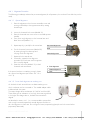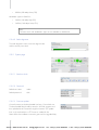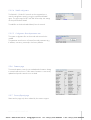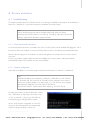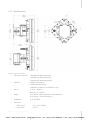
1
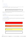
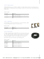
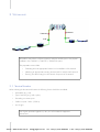
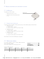
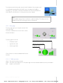
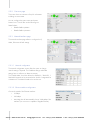
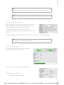
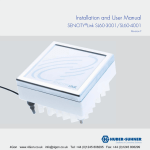
Installation and User Manual
SL60-401 / SL60-501 / SL60-4010
Revision 2011-03-23.1
4Gon www.4Gon.co.uk [email protected] Tel: +44 (0)1245 808295 Fax: +44 (0)1245 808299
4Gon www.4Gon.co.uk [email protected] Tel: +44 (0)1245 808295 Fax: +44 (0)1245 808299
TABLE
OF
CONTENTS
1 Introduction
6
1.1 Intended users
6
1.2 Revision
6
1.3 Prior knowledge
6
1.4 Used symbols
6
1.5 Warranty
7
1.6 Copyright / Disclaimer
7
2 System overview
2.1 General description
8
8
2.1.1 Benefits
8
2.1.2 Applications
8
2.2 System components
9
2.2.1 Terminals
9
2.2.2 Alignment bracket
9
2.2.3 Alignment tool
10
2.2.4 Weather shield
10
2.2.5 Sealed Ethernet connector
10
2.2.6 Accessories
10
2.2.6.1 PoE injector
10
2.2.6.2 Data line protector
11
2.2.6.3 Mast bracket
11
2.2.6.4 Ethernet cables
11
3 Site planning
12
3.1 Terminal location
12
3.2 Line of sight
13
3.3 Link distance / Link availability
13
3.4 Terminal mounting options
13
3.4.1 Wall mounting
13
3.4.2 Pole mounting
14
3.5 Cabling
14
3.6 Grounding / Lightning protection
14
3.7 Co-located applications
14
4 Installation
15
4.1 Mount installation
15
4.1.1 Wall mount
15
4.1.2 Mast mount
15
4.2 Terminal installation
16
4.3 Cable installation
16
4.4 Antenna alignment
16
4.4.1 Alignment Procedure
17
4.4.1.1 Optical alignment
17
4.4.1.2 Power level alignment via auxiliary port
17
© 2010 HUBER+SUHNER AG
3
4Gon www.4Gon.co.uk [email protected] Tel: +44 (0)1245 808295 Fax: +44 (0)1245 808299
4.4.1.3 Power level alignment via web interface
18
4.5 Grounding
18
4.6 Lightning / Surge protector
18
4.7 Power injector
19
5 Terminal management and monitoring functions
5.1 Auxiliary port
5.1.1 Parameter reset via auxiliary port
5.2 Web browser interface
5.2.1 Entry page
5.2.1.1 Traffic light colors
20
20
20
20
21
21
5.2.2 Overview page
22
5.2.3 Network Interface page
22
5.2.3.1 Network configuration
22
5.2.3.2 Ethernet interface configuration
22
5.2.3.3 Quality of Service (QoS)
23
5.2.4 Air Interface page
23
5.2.4.1 Local terminal and modem configuration
23
5.2.4.2 Radio alignment
24
5.2.5 System page
24
5.2.5.1 Real time clock
24
5.2.5.2 Password
24
5.2.5.3 Firmware update
24
5.2.5.4 SNMP configuration
25
5.2.5.5 Configuration file and parameter reset
25
5.2.6 Statistics page
25
5.2.7 Service (Expert) page
25
5.3 SNMP interface
26
A Technical information
27
A.1 Troubleshooting
27
A.1.1 Power and network connection
27
A.1.2 Network configuration
27
A.1.3 Duplex mismatch
28
A.1.4 Miss-alignment
28
A.2 Specifications
29
A.2.1 Ethernet cable colour code
31
A.3 Receiver level / Rain / Link distance
32
A.4 Availability / Rain zone / Link distance
33
A.4.1 Map of America
34
A.4.2 Map of Asia and Middle East
35
A.4.3 Map of Europe
36
B Regulatory information
37
B.1 FCC statement
37
B.2 Industry Canada statement
38
B.3 CE – Declaration of conformity
38
B.4 Safety
39
4
www.hubersuhner.com
4Gon www.4Gon.co.uk [email protected] Tel: +44 (0)1245 808295 Fax: +44 (0)1245 808299
B.4.1 English
39
B.4.2 Deutsch
40
B.4.3 Français
40
B.4.4 Italiano
40
C Contacts
41
C.1 Technical assistance
41
C.2 Service center / RMA
41
D Glossary
42
© 2010 HUBER+SUHNER AG
5
4Gon www.4Gon.co.uk [email protected] Tel: +44 (0)1245 808295 Fax: +44 (0)1245 808299
1 INTRODUCTION
1.1 Intended users
This manual is intended for all installation and service personnel who are involved in the planning, installation,
operation and maintenance of SL60-401 / SL60-501 / SL60-4010 equipment.
Please read the complete SL60-401 / SL60-501 / SL60-4010 (SENCITY®Link)
manual prior to its unpacking, installation, setup and deployment.
Although the SENCITY®Link is designed for easy installation and setup, optimum performance can be achieved by
following the procedures outlined in this manual.
1.2 Revision
HUBER+SUHNER reserves the right to revise this documentation periodically without any obligation to provide
notification of such revision or changes. The latest revision can be downloaded at http://www.sl60.com.
1.3 Prior knowledge
This manual assumes that the installer has at least a basic experience and understanding of networking equipment,
as well as some familiarity with its configuration and operation. The information covered in this manual should be
fully understood prior to installation.
1.4 Used symbols
Danger
Not used
Warning
Risk for human and equipment
Caution
Risk for equipment and functionality
Advice
6
www.hubersuhner.com
4Gon www.4Gon.co.uk [email protected] Tel: +44 (0)1245 808295 Fax: +44 (0)1245 808299
1.5 Warranty
HUBER+SUHNER warrants to the original end user (purchaser) that this product is free from any defects in materials
or workmanship for a period of up to one year from the date of shipment to the end user.
During the warranty period, and upon proof of purchase, should the product show indications of failure due to faulty
workmanship and/or materials, HUBER+SUHNER will, at its discretion, repair or replace the defective products or
components without charge for either parts or labor, and to whatever extent it shall deem necessary to restore the
product or components to full operating condition. Any replacement will consist of a new or remanufactured,
functionally equivalent product of equal value, and will be offered solely at the discretion of HUBER+SUHNER.
This warranty shall not apply if the product is modified (e.g. warranty seal is broken), misused, tampered with,
damaged by an act of God, or subjected to abnormal working conditions.
To obtain services under this warranty, contact HUBER+SUHNER‘s Service Center, referring to your Return Material
Authorization number (see C.2). Products must be returned Postage Prepaid. It is recommended that the terminal be
insured when shipped. Any products returned without either proof of purchase or with an outdated warranty will be
repaired or replaced and the customer will be billed for parts and labor. All repaired or replaced products will be
shipped by HUBER+SUHNER to the corresponding return address ‘Postage Paid’ (USA only). If the customer
specifies some other return destination beyond US borders, the customer shall bear the cost of the return shipment.
This warranty gives you specific legal rights, and you may also have other rights that vary from state to state.
1.6 Copyright / Disclaimer
Copyright © 2011 by HUBER+SUHNER
The contents of this publication may not be reproduced in any part or as a whole, transcribed, stored in a retrieval
system, translated into any language, or transmitted in any form or by any means, electronic, mechanical, magnetic,
optical, chemical, photocopying, manual, or otherwise, without the prior written permission of HUBER+SUHNER.
© 2010 HUBER+SUHNER AG
7
4Gon www.4Gon.co.uk [email protected] Tel: +44 (0)1245 808295 Fax: +44 (0)1245 808299
2 SYSTEM
OVERVIEW
2.1 General description
The SL60-401 / SL60-501 / SL60-4010 system operates as a data link in the
unlicensed 60 GHz band between 57 GHz and 64 GHz and delivers a full
duplex data rate of up to 320 Mbps (SL60-401) over a distance of up to 1600
m (5249 ft) (SL60-501).
Measuring only 18 cm × 18 cm (7“ × 7“), the terminal’s compact size is attained
by extensively integrating the active and passive components.
For more detailed technical data see appendix A.2.
2.1.1 Benefits
•
Easy installation – The concept of the SENCITY®Link allows to the end user to install it as easy as any other
network component.
The single cable solution reduces the complexity of the installation. The terminal is connected to the network,
monitored and supplied with power through a single outdoor rated CAT 6 Ethernet cable.
The visual alignment tool and an alignment bracket allows the user to easily install the link.
Immediate operation without the need of additional configuration is granted.
•
Network performance – Guaranteed full duplex 320 Mbps (SL60-401) along the complete range. Unlike
typical WLAN equipment the user can transmit a full 320 Mbps (SL60-401) over the link.
•
License free operation – The system has been approved and can be operated in many countries.
•
System administration – To monitor the status and the traffic the user can access the link statistics either via
the HTML user interface or by integrating it into a network management tool via SNMP.
•
Security – The proprietary radio interface does not allow any other system to access the 60 GHz
transmitted data.
A high level of data security is inherent in the product via signal absorption by atmospheric oxygen and the
use of high gain/narrow beam width antennas.
2.1.2 Applications
•
LAN extension
•
Redundant access
•
Campus connectivity
•
Disaster recovery
•
Wireless backhaul
•
Centralization of IT infrastructure
•
Temporary connections during events
•
Mesh and hub and spoke configuration
8
4Gon www.4Gon.co.uk [email protected] Tel: +44 (0)1245 808295 Fax: +44 (0)1245 808299
2.2 System components
The SL60-401 / SL60-501 / SL60-4010 system is composed of the following components:
•
Terminal A and Terminal B
•
Alignment brackets
•
Alignment tool
•
Weather shields
•
Sealed Ethernet connections
•
Mounting set
•
Manual
•
Main accessories:
•
•
PoE injector
•
Data line protector
•
Mast bracket
•
Ethernet cables
Required tools:
•
Adjustable wrench
2.2.1 Terminals
The terminals are the main system components. They combine the antenna,
transmitter and receiver and are connected to the network via a standard Ethernet
cable with RJ-45 connector.
Power is supplied through the Ethernet cable to the terminal. This will require either
a PoE+ (802.3at) compatible network equipment or an additional PoE injector.
2.2.2 Alignment bracket
The alignment bracket facilitates installation and positioning owing to its
independent axis with coarse and fine alignment capabilities.
© 2010 HUBER+SUHNER AG
9
4Gon www.4Gon.co.uk [email protected] Tel: +44 (0)1245 808295 Fax: +44 (0)1245 808299
2.2.3 Alignment tool
The optical alignment tool provided is easily mounted on the terminal using an
elastic band. It enables both ends of the link to be aligned quickly, simply and
independently.
2.2.4 Weather shield
The weather shield offers an additional protection for the terminal against rain,
sun, snow, ice formation and bird droppings.
2.2.5 Sealed Ethernet connector
The seal kit is used to make a watertight connection of the Ethernet coupling. Please use the
separate instructions for a proper installation of the seal kit.
2.2.6 Accessories
2.2.6.1
PoE injector
The terminal is powered via Ethernet cable according to the IEEE 802.3at PoE+
standard. Should the network equipment connected to the SENCITY ®Link does not
offer PoE, a power injector can be inserted in line to the Ethernet cable.
Order information:
Item number
Description
84021333
PoE+ 802.3at Power Injector
10
4Gon www.4Gon.co.uk [email protected] Tel: +44 (0)1245 808295 Fax: +44 (0)1245 808299
2.2.6.2
Data line protector
HUBER+SUHNER strongly recommends the installation of an outdoor data line protector to provide lightning and
surge protection for the building, personnel and equipment. Please refer to the local and/or national electrical and
building codes.
Order information:
Item number
Description
<on request>
Data line protector (indoor)
To use only in combination with an outdoor protector.
<on request>
2.2.6.3
Data line protector (outdoor)
Mast bracket
The mast bracket is used to mount the bracket onto a mast. The bracket is suitable
for any pole diameter from 50 mm to 115 mm (2” to 4,5”).
Order information:
Item number
Description
84015652
Mast Bracket
2.2.6.4
Ethernet cables
The length of the cable linking the SENCITY®Link to the next network node may be
up to 100 m (328 ft) in length. It should, however, be kept as short as practical in
order to minimize signal losses. All Ethernet cables must be CAT 5e (or better)
compliant and suitable for outdoor use. The cable must be UV stable, UL
approved and comply with local and/or national building codes.
Order information:
Item number
Description
84031068
Outdoor Ethernet Cable 2 m
84028025
Outdoor Ethernet Cable 10 m
84028026
Outdoor Ethernet Cable 30 m
84041974
Outdoor Ethernet Cable 50 m
84028029
Outdoor Ethernet Cable 90 m
© 2010 HUBER+SUHNER AG
11
4Gon www.4Gon.co.uk [email protected] Tel: +44 (0)1245 808295 Fax: +44 (0)1245 808299
3 SITE
PLANNING
Protector
PoE
Protector
PoE
All installers must perform a full site inspection and plan carefully prior to the physical
installation of an SL60-401 / SL60-501 / SL60-4010 system.
This preparation must include:
•
Evaluating the most appropriate location for the installation of the terminal.
•
Identifying an appropriate mounting structure (wall or mast) for each terminal.
•
Planning the cable routing from the network component to the terminal.
3.1 Terminal location
When selecting the best terminal location the following factors should be considered:
•
Accessibility (e.g. roof)
•
Type of mounting (e.g. wall or pole)
•
Grounding connection point
•
Cable runs (max. 100 m / 328 ft)
•
Line of sight
Use of given protection against sun, rain, etc. will increase the equipment
performance.
12
4Gon www.4Gon.co.uk [email protected] Tel: +44 (0)1245 808295 Fax: +44 (0)1245 808299
3.2 Line of sight
To ensure a clear line of sight, there must be no obstructions between the two terminal locations. The required
clearance can be established visually using the following table1:
Link distance
Boundary diameter
100 m
(328 ft)
0.7 m
(2.3 ft)
200 m
(656 ft)
1.0 m
(3.3 ft)
400 m
(1312 ft)
1.4 m
(4.6 ft)
600 m
(1968 ft)
1.7 m
(5.6 ft)
800 m
(2625 ft)
2.0 m
(6.6 ft)
Boundary diameter
Link distance
3.3 Link distance / Link availability
The link distance is directly related to the weather conditions.
The affordable link availability is influenced by the following environmental conditions:
•
Rain: the less, the better
•
Temperature: the higher, the better
•
Air pressure: the lower, the better
Knowledge of the link distance (line of sight) is important in estimating link quality.
For different maps of the world including the rain regions see appendix A.4.
3.4 Terminal mounting options
3.4.1 Wall mounting
The wall mounting location should be strong enough to secure the terminal to the wall,
taking into account all foreseeable environmental conditions (e.g. wind, rain, ice).
1
Fresnel zone calculation
© 2010 HUBER+SUHNER AG
13
4Gon www.4Gon.co.uk [email protected] Tel: +44 (0)1245 808295 Fax: +44 (0)1245 808299
Depending on the material to which the bracket is mounted, differently sized mounting hardware may be necessary.
To mount the terminal onto the bracket use the enclosed M6 bolts. The bracket
50°
allows a tilt angle of +/- 50° in both axis.
3.4.2 Pole mounting
The pole mounting kit will be needed to mount the terminal onto poles with diameters from 50 mm to 115 mm (2” to
4,5”).
3.5 Cabling
The terminal is delivered with an Ethernet cable terminated with a RJ-45 plug connector. To connect the
SENCITY®Link to your network, use a CAT 5e (or better) Ethernet cable with a maximum length of 100 m to the next
network node. Please verify too that the cable used is designed for outdoor environments (e.g. water, solar UV).
Since the power is supplied by the Ethernet cable, please make sure that network equipment used supports Power
over Ethernet (PoE). If not, use a PoE injector according to IEEE 802.3at (PoE+). SENCITY ®Link can handle crossover
and straight cables.
3.6 Grounding / Lightning protection
The terminal must be properly grounded to provide protection against voltage surges.
In the event of a short circuit or lightning strike, effective grounding can prevent damage to building, equipment,
infrastructure and personnel. For installations in the USA, refer to Article 830 of the National Electrical Code
(Network-powered broadband communications systems), for all other countries, implement protection in accordance
with the safety standards and regulatory requirements of the country in which the equipment is installed.
HUBER+SUHNER strongly recommends the use of outdoor lightning protectors.
3.7 Co-located applications
Owing to the compact size of the SL60-401 / SL60-501 / SL60-4010 integrated terminal, it is particularly suitable
for co-sited applications. Possible configurations include:
•
Back-to-back - e.g. doubles the link distance
•
Parallel link - doubles data capacity or redundancy
•
Star - hub and spoke
To deploy a co-sited application, please contact HUBER+SUHNER to assist with devising an appropriate site
design.
14
4Gon www.4Gon.co.uk [email protected] Tel: +44 (0)1245 808295 Fax: +44 (0)1245 808299
4 INSTALLATION
Owing to the small size and integrated design of the SENCITY®Link, its correct installation and setup is relatively
simple.
Nevertheless, when working on a roof, ladder, mast or staging, please take extreme
care, observing all facility and OSHA (or other applicable regulatory agency) required
safety precautions.
4.1 Mount installation
4.1.1 Wall mount
The wall and mounting screws must be able to support a weight of 11 pounds (5 kg),
taking into account associated wind and potential ice loading factors.
Right
Wrong
4.1.2 Mast mount
•
Ensure that the mast used has a diameter of between 50 mm to 115 mm
(2” to 4.5”).
•
Use a 13 mm flat wrench (~½”) to fasten the M8 screw nut.
•
Fasten the alignment bracket onto front part of mast bracket using the
enclosed stainless steel screws, nuts and washer (M6).
•
Fix the front part of the mast bracket and the attached alignment bracket on the mast.
Do not use zinc plated screws as these will corrode and endanger link performance
and environment.
© 2010 HUBER+SUHNER AG
15
4Gon www.4Gon.co.uk [email protected] Tel: +44 (0)1245 808295 Fax: +44 (0)1245 808299
4.2 Terminal installation
It is important to install the terminal on the bracket with
the same orientation (antenna polarization) at both
Polarization
ends of the link. The terminal must be mounted on the
direction
bracket in such a way that the polarization arrow
points to the same direction at both ends of the link.
The terminal must be mounted on the bracket by using
the allen key with the enclosed stainless steel screws
(M6 x 12).
Do not use zinc plated screws as these will corrode and endanger link performance
and environment.
4.3 Cable installation
The length of the cable from the terminal to the next network component may be
up to 100 m (328 ft) in length, but should be kept as short as practical in order to
reduce signal loss. All Ethernet cables must be CAT 5e compliant and suitable for
outdoor use. The cable must be UV stable, UL approved and must comply with
local and/or national building codes.
To enter the building, HUBER+SUHNER recommends using cable seals from Roxtec
(http://www.roxtec.com).
4.4 Antenna alignment
One of SENCITY®Link’s biggest advantage is its fast, easy alignment procedure.
The terminals can be aligned optically by using the alignment tool. No electrical alignment is required, although
possible.
The table below shows the alignment tolerance:
Link distance
Alignment
accuracy
100 m
328 ft
0.9 m
2.9 ft
400 m
1312 ft 3.5 m
11.5 ft
600 m
1968 ft 5.2 m
17.2 ft
800 m
2625 ft 7.0 m
22.9 ft
Alignment accuracy
nce
is ta
d
k
Lin
16
4Gon www.4Gon.co.uk [email protected] Tel: +44 (0)1245 808295 Fax: +44 (0)1245 808299
4.4.1 Alignment Procedure
The following procedure(s) achieves fast, accurate alignment (for all operations, the enclosed 5 mm allen key can be
used).
4.4.1.1
Optical alignment
1. Place the alignment tool to the most accessible corner and
ensure good visibility to the opposite terminal by rotating
the telescope.
2. Loosen the horizontal lock screws (labeled “3”)
3. Place the horizontal axis course screw in its middle position
(needle).
4. Carry out a rough alignment on the horizontal axis and
fasten the screw (labeled “1”).
5. Repeat steps b), c) and d) for the vertical axis.
6. Turn the horizontal course screw (labeled “2”)
by viewing through the telescope and
carrying out the fine alignment.
Horizontal alignment
Wall
Vertical alignment
7. Repeat e) for the vertical axis.
8. If necessary, repeat the fine alignment
procedure e) for both axes until the opposite
link is correctly aligned.
9. Fasten the lock screw (labeled “3”) on both
horizontal and vertical axes.
If the power levels are not satisfying enough, please
2 Fine alignment
1 Coarse alignment
3 Lock
do a power level alignment (see section 4.4.1.2 or
4.4.1.3).
4.4.1.2
Power level alignment via auxiliary port
On the back of each terminal there is a QMA auxiliary port to
which a voltmeter can be connected to. The needed adapter cable
is delivered with the system.
The output voltage values are between 0.5 Volt DC and 3 Volt DC.
These values give an indication on how high the receive signal level
is: the higher the voltage value is, the better the terminals are
aligned.
As described in section 4.4.1.1, it is recommended to proceed first
with a rough horizontal (respectively vertical) alignment and then to
do a fine alignment on each axis. Do not forget to loosen (respectively tighten) the two lock screws before
(respectively afterwards).
© 2010 HUBER+SUHNER AG
17
4Gon www.4Gon.co.uk [email protected] Tel: +44 (0)1245 808295 Fax: +44 (0)1245 808299
4.4.1.3
Power level alignment via web interface
The power level can be accessed via the web interface (see section 5.2.4.2) too.
As described in section 4.4.1.1, it is recommended to proceed first with a rough horizontal (respectively vertical)
alignment and then to do a fine alignment on each axis. Do not forget to loosen (respectively tighten) the two lock
screws before (respectively afterwards).
See chapter A.3 for an estimation of the power levels at different rain rates and link distances.
A power level of -60dBm is better than a power level of -70dBm
4.5 Grounding
The terminal must be properly grounded.
Two screws are provided on the reverse housing of the
terminal to facilitate the correct grounding. To fasten
Grounding screws
the grounding cable onto the terminal, use a lug and
serrated washer combined with an M8 nut.
Connect the terminal to the connection points nearest
to the building-to-earth ground point. The grounding
conductor must be as short as is practical and should
not exceed 6 m (20 ft). For installations in the USA, refer to Articles 830 of the National Electrical Code (Networkpowered broadband communications systems). For installations in all other countries, refer to the safety standards
and regulatory requirements.
4.6 Lightning / Surge protector
HUBER+SUHNER strongly recommends the use of outdoor data line protectors.
To protect humans and the building a protector must be installed before the cable
enters the building. For detailed installation instructions, please refer to the
dedicated documents enclosed to the protectors. Also see chapter 2.2.6.2 for
available data line protectors.
18
4Gon www.4Gon.co.uk [email protected] Tel: +44 (0)1245 808295 Fax: +44 (0)1245 808299
4.7 Power injector
The power injector is connected inline into the data line. The maximum distance
between the PoE injector and the SENCITY®Link is 100 m (328 ft). The PoE
injector must be IEEE 802.3at compliant (PoE+).
© 2010 HUBER+SUHNER AG
19
4Gon www.4Gon.co.uk [email protected] Tel: +44 (0)1245 808295 Fax: +44 (0)1245 808299
5 TERMINAL
MANAGEMENT AND MONITORING FUNCTIONS
5.1 Auxiliary port
The auxiliary port can be used for
Auxiliary port
•
alignment (see section 4.4.1.2)
•
parameter reset of the terminal (see section
5.1.1)
5.1.1 Parameter reset via auxiliary port
To reset all parameters (IP address, username, password, etc.) to factory default, please proceed as follows:
1. Unplug the connector
a)
Wait for approx. 1 second
b)
Plug the connector (make sure you hear the “click”)
2. Unplug the connector
a)
Wait for approx. 1 second
b)
Plug the connector (make sure you hear the “click”)
3. Unplug the connector
a)
Wait for approx. 1 second
b)
Plug the connector (make sure you hear the “click”)
Terminal will then reboot with the default system configuration.
5.2 Web browser interface
For an initial configuration, use a PC or laptop. Address the terminal
with the appropriate IP address.
Every terminal is labeled with its terminal type (A or B).
The factory default values are:
Terminal
IP address
Subnet mask
User name
Password
A
192.168.0.21
255.255.255.0
admin
sl60
B
192.168.0.22
255.255.255.0
admin
sl60
20
4Gon www.4Gon.co.uk [email protected] Tel: +44 (0)1245 808295 Fax: +44 (0)1245 808299
To communicate with the terminal, ensure that the IP address of the computer used
is not allocated automatically by the DHCP server. Configure the IP address
manually (e.g. 192.168.0.1 with subnet mask 255.255.255.0). Remember to
ensure that your web browser is not using any proxy server settings.
Note:
The IP address settings have no influence on data connectivity. This settings are only
needed to access the monitoring functions of the terminal.
5.2.1 Entry page
The entry page gives you a simple overview of the
current link status.
The screen is divided into the “local” and “remote”
terminal information.
The three graphics show the
•
RF detection status
•
signal-to-noise ratio
•
receive signal level
Receive signal level (RSL)
Signal-to-noise ratio (SNR)
RF detection status
Click “Continue” to enter the detailed web browser
interface.
5.2.1.1
Traffic light colors
Green: The system is working correctly
Yellow: The system's link margin is low. The system might work with intermittent detection and synchronization
Red:
System is not functional
© 2010 HUBER+SUHNER AG
21
4Gon www.4Gon.co.uk [email protected] Tel: +44 (0)1245 808295 Fax: +44 (0)1245 808299
5.2.2 Overview page
This screen shows an overview of key link information
including its current status.
You can configure the system name and system
location here. This will also set the following two
SNMP values:
•
SNMPv2-MIB::sysName
•
SNMPv2-MIB::sysLocation
5.2.3 Network Interface page
The network interface page allows to configure the IP,
VLAN, Ethernet and QoS settings.
5.2.3.1
Network configuration
The network configuration screen offers the option to change
network settings if required. The IP address settings and VLAN
settings have no influence on data connectivity.
The “Enable VLAN” check box allows the SL60-401 / SL60-501 /
SL60-4010 terminals to be accessed when the link is integrated into
a VLAN trunk. The VLAN ID needs to be set then too.
5.2.3.2
Ethernet interface configuration
Choose the speed of the Ethernet interface:
•
10 Mbps
•
100 Mbps
•
Auto Neg (this will automatically choose 1000 Mbps if the
interface you connect to is capable of Gigabit Ethernet)
22
4Gon www.4Gon.co.uk [email protected] Tel: +44 (0)1245 808295 Fax: +44 (0)1245 808299
Note:
Gigabit Ethernet standards require auto-negotiation to be on in order to operate.
Note:
SL60-4010 does support Ethernet interface speeds of 10 Mbps and 100 Mbps only.
5.2.3.3
Quality of Service (QoS)
Egress limiting (output on air interface) can be either switched of or
done on a VLAN base (Class of Service, IEEE 802.1p) or on a
content base (using the first three bits of the Type of
Service/Differentiated Services field in the IP header).
Four different mappings of the priority level to the priority queue can
be set.
Ingress limiting (input on Ethernet interface) can be set to “flow control” or to “random early discard”.
Note:
QoS settings are not available for SL60-4010
5.2.4 Air Interface page
The air interface page allows to configure the modem
and to view the current RX power level.
5.2.4.1
Local terminal and modem configuration
Modulation types for SL60-401:
•
320hfec (320 Mbps light FEC)
© 2010 HUBER+SUHNER AG
23
4Gon www.4Gon.co.uk [email protected] Tel: +44 (0)1245 808295 Fax: +44 (0)1245 808299
•
320lfec (320 Mbps heavy FEC)
Modulation types for SL60-501:
•
160lfec (160 Mbps light FEC)
•
160hfec (160 Mbps heavy FEC)
Note:
“TX Power Level” and “Modulation Type” are not available on SL60-4010.
5.2.4.2
Radio alignment
The radio alignment screen shows the alignment bar
and the receive power level.
5.2.5 System page
5.2.5.1
Real time clock
5.2.5.2
Password
Default user name:
admin
Default password:
sl60
5.2.5.3
Firmware update
Current firmware can be downloaded from http://www.sl60.com.
The downloaded file(s) should be saved on the local computer and
then uploaded to each terminal through the firmware TFTP update
form on the web interface. A TFTP server is needed for this.
Please follow the installation instructions given with the upgrade file(s).
24
4Gon www.4Gon.co.uk [email protected] Tel: +44 (0)1245 808295 Fax: +44 (0)1245 808299
5.2.5.4
SNMP configuration
The SL60-401 / SL60-501 terminal can be integrated into a
network management system by using the implemented SNMP
agent. This agent supports GET and TRAP functionality. No settings
can be performed via SNMP.
The MIB file can be downloaded directly from the terminal.
5.2.5.5
Configuration file and parameter reset
The system configuration file can be stored and restored when
needed.
The parameter reset function will reset all terminal parameters (e.g.
IP address, username, password) to the factory defaults.
5.2.6 Statistics page
The network statistics screen shows standardized information relating
to network traffic and errors. Traffic status information is continuously
updated and specific network errors are listed.
5.2.7 Service (Expert) page
Please use this page only when advised by the customer support.
© 2010 HUBER+SUHNER AG
25
4Gon www.4Gon.co.uk [email protected] Tel: +44 (0)1245 808295 Fax: +44 (0)1245 808299
5.3 SNMP interface
Object
OID
OID type
Description
HUBERSUHNER-MIB sencity2
(.iso.org.dod.internet.private.enterprises.hubersuhnerOID.sencity2.x / .1.3.6.1.4.1.25358.2.x)
sencityLinkQuality
.1.
Integer
1: Green
2: Yellow
3: Red
sencityReceivePower
.10.
Integer
Receive signal level [dBm]
sencityTemperature
.11.
Integer
Temperature [°C]
sencityLockDetector
.12.
Integer
Lock detector status
1: locked
0: unlocked
sencityFirmwareversion
.21.
String
Installed firmware version
sencityAuxVoltage
.25.
String
Voltage at auxiliary port [V]
HUBERSUHNER-MIB sencitytraps
(.iso.org.dod.internet.private.enterprises.hubersuhnerOID.sencity2.sencityTraps.x / .1.3.6.1.4.1.25358.2.22.x)
sencityLinkQualityImprovedTrap
.1.
Integer
1: from red to green
2: from red to yellow
3: from yellow to green
sencityLinkQualityReducedTrap
.2.
Integer
1: from green to yellow
2: from green to red
3: from yellow to red
sencityTemperatureHighTrap
.3.
Integer
A trap indicating that the temperature within
the terminal has crossed the 70° Celcius
threshold
sencityTemperatureLowTrap
.4.
Integer
A trap indicating that the temperature within
the terminal has crossed the -40° Celcius
threshold
26
4Gon www.4Gon.co.uk [email protected] Tel: +44 (0)1245 808295 Fax: +44 (0)1245 808299
A TECHNICAL
INFORMATION
A.1 Troubleshooting
This chapter provides solutions to problems that can occur during the installation and operation of the SL60-401 /
SL60-501 / SL60-4010. It covers various aspects of installation and network setup.
Note:
Each of the following points must be checked at both ends of the link. Start by
performing the entire procedure on one side (e.g. Terminal A). If this does not solve the
problem, repeat all the steps at the opposite terminal.
A.1.1 Power and network connection
You must verify that the terminal is connected to the power. The PoE injector must be installed and plugged in. Go to
the terminal, disconnect the RJ-45 connector and verify if there is power in the cable using a standard PoE tester.
Take the cable and plug it into a notebook or a network testing device and verify if there is a correct network
connection.
If there is any problem, please replace the cable and validate the connection again. We provide special,
preassembled outdoor CAT 5e cables to ensure easy installation.
A.1.2 Network configuration
Check that the IP address is in the same range and subnet as the SL60-401 / SL60-501 / SL60-4010.
Note:
The default IP address of the SL60-401 / SL60-501 / SL60-4010 is 192.168.0.21
for Terminal A and 192.168.0.22 for Terminal B. All the computers on the network
must have a unique IP address in the same range, e.g. 192.168.0.X. Any computers
with identical IP addresses will not be visible on the network.
They must all, therefore, have the same subnet mask (e.g. 255.255.255.0).
Do a Ping test to make sure that the SL60-401 / SL60501 / SL60-4010 is responding. Go to Start → Run
→ Type “Command” → Type “ping 192.168.0.X”.
A successful Ping test will generate four replies.
As soon as the network configuration is correct you
can access the GUI (Graphical User Interface) and
check the settings according to section 4.9.
© 2010 HUBER+SUHNER AG
27
4Gon www.4Gon.co.uk [email protected] Tel: +44 (0)1245 808295 Fax: +44 (0)1245 808299
A.1.3 Duplex mismatch
If you encounter bad network performance, you probably have a duplex mismatch.
To ensure that the SL60-401 / SL60-501 / SL60-4010 terminal and the connected network component (e.g.
switch) do not have a duplex mismatch you must first check your statistics.
If you find many input errors, you are on the full-duplex side; if you see many late collisions, you are on the halfduplex side.
To solve the duplex mismatch, you must manually configure both network components to the same values.
A.1.4 Miss-alignment
See the configuration interface as described in section 5.2.3.1. On the Radio alignment screen (see section
5.2.4.2) you see the signal strength in dBm (e.g. -30 dBm). If the value is below -95 dBm the receiver is not in the
correct position to track the signal. You therefore need to re-align the terminal to its opposite terminal (please follow
the instructions in section 4.4.1).
28
4Gon www.4Gon.co.uk [email protected] Tel: +44 (0)1245 808295 Fax: +44 (0)1245 808299
A.2 Specifications
General system information
•
Transmission capacity:
320 Mbps full duplex (SL60-401)
160 Mbps full duplex (SL60-501)
100 Mbps full duplex (SL60-4010)
•
Interfaces:
10 Base-T (all versions)
100 Base-TX (all versions)
1000 Base-T (SL60-401 and SL60-501 only)
•
Latency:
< 50 µs + distance
latency (1 µs / 300 m)
•
Range*:
up to 800 m, 2625 ft (SL60-401 and SL60-4010)
up to 1600 m, 5249 ft (SL60-501)
•
Availability*:
•
Connection
up to 99.999%
•
Cable length:
max. 100 m (300 ft)
•
Signal wires:
CAT 5e
© 2010 HUBER+SUHNER AG
29
4Gon www.4Gon.co.uk [email protected] Tel: +44 (0)1245 808295 Fax: +44 (0)1245 808299
•
Connector:
RJ–45 (male; including outdoor Ethernet seal kit)
Mechanical data
•
Dimension:
182 x 182 x 68 mm (6.4“ x 6.4“ x 3.5“)
•
Weight:
2.5 kg (5.5 lb) terminal, 1 kg (2.2 lb) bracket
System administration
•
Web browser-based configuration
•
SNMP
Power supply
•
Standards:
Compliant to Power over Ethernet according to IEEE 802.3at
•
Voltage:
± 48 V DC
•
Power consumption:
18 W
Environmental data
•
Working temperature **: - 45 °C ... + 55 °C
(- 49 °F … + 131 °F)
•
Storage temperature:
- 30 °C … + 55 °C
(- 22 °F … + 131 °F)
•
Wind load:
operating
160 km/h (100 mph)
survival
200 km/h (125 mph)
Regulatory compliance
•
FCC Part 15
•
Industry Canada RSS210
•
R&TTE Directive 1999/5/EC
Ordering information
•
SL60-401: Item # 84092438
SL60-501: Item # 84092442
SL60-4010: Item # 84119340
each composed of:
2 terminals
2 alignment brackets
1 manual
2 mounting sets
2 weather shields
* The range depends on the climate zone and the requested availability
** Only if the terminal is powered up
30
4Gon www.4Gon.co.uk [email protected] Tel: +44 (0)1245 808295 Fax: +44 (0)1245 808299
A.2.1 Ethernet cable colour code
Note:
By cutting of the connector the warranty will expire.
Pin
RJ45 Plug
1
Black
2
Green
3
Red
4
Blue
5
White
6
Orange
7
Yellow
8
Brown
Twisted pairs:
•
Black (1) / Green (2)
•
Yellow (7) / Brown (8)
•
Red (3) / Orange (6)
•
Blue (4) / White (5)
© 2010 HUBER+SUHNER AG
31
4Gon www.4Gon.co.uk [email protected] Tel: +44 (0)1245 808295 Fax: +44 (0)1245 808299
A.3 Receiver level / Rain / Link distance
The following diagram shows the approximate receiver levels at different rain rates and distances.
SL60-401
SL60-501
Note:
This diagram is valid for the highest possible output power that can be configured (see
chapter 5.2.4.1).
32
4Gon www.4Gon.co.uk [email protected] Tel: +44 (0)1245 808295 Fax: +44 (0)1245 808299
A.4 Availability / Rain zone / Link distance
The link distance is directly related to the weather conditions. The table below refers to a link working at a distance
of up to 800m (SL60-401 / SL60-4010), respectively 1600m (SL60-501), for dry weather conditions. Please also
refer to the maps in sections A.4.1, A.4.2 and A.4.3.
800m (SL60-401 / SL60-4010):
Availability
Rain zone *
Link distance (m)
A
B
C
D
E
F
G
H
J
K
L
M
N
P
Q
99%
797
789
785
764
787
770
752
765
701
772
765
741
730
669
597
99.9%
765
752
730
701
719
701
669
684
618
669
648
607
549
461
446
99.99%
701
669
648
624
607
578
569
561
549
524
473
466
405
343
376
99.999%
607
561
524
524
450
434
461
425
486
397
338
370
312
268
320
K
L
M
N
P
Q
1600m (SL60-501):
Availability
Rain zone *
Link distance (m)
A
99%
99.9%
99.99%
99.999%
B
C
D
E
F
G
H
J
1593 1571 1562 1508 1566 1522 1479 1512 1354 1530 1512 1450 1424 1278 1111
1512 1479 1424 1354 1399 1354 1278 1314 1159 1278 1229 1135 1005 817
785
1354 1278 1229 1172 1135 1069 1050 1031 1005 951
841
826
701
578
644
1135 1031 951
569
632
520
438
535
951
794
761
817
742
868
685
* Rain zone according to ITU-R Recommendation PN.837-1
99.9% availability equates to 526 minutes per year of outage due to heavy rains.
99.99% availability equates to 53 minutes per year of outage due to heavy rains.
99.999% availability equates to 5 minutes per year of outage due to heavy rains.
© 2010 HUBER+SUHNER AG
33
4Gon www.4Gon.co.uk [email protected] Tel: +44 (0)1245 808295 Fax: +44 (0)1245 808299
A.4.1 Map of America
34
4Gon www.4Gon.co.uk [email protected] Tel: +44 (0)1245 808295 Fax: +44 (0)1245 808299
A.4.2 Map of Asia and Middle East
© 2010 HUBER+SUHNER AG
35
4Gon www.4Gon.co.uk [email protected] Tel: +44 (0)1245 808295 Fax: +44 (0)1245 808299
A.4.3 Map of Europe
36
4Gon www.4Gon.co.uk [email protected] Tel: +44 (0)1245 808295 Fax: +44 (0)1245 808299
B REGULATORY
INFORMATION
B.1 FCC statement
Changes or modifications not expressly approved by the party responsible for compliance could void the user's
authority to operate the equipment.
This device complies with Part 15 of the FCC Rules.
Operation is subject to the following two conditions:
1. this device may not cause harmful interference, and
2. this device must accept any interference received, including interference that may cause undesired
operation.
Note: This equipment has been tested and found to comply with the limits for a Class B digital device, pursuant to
part 15 of the FCC Rules. These limits are designed to provide reasonable protection against harmful interference in
a residential installation. This equipment generates, uses and can radiate radio frequency energy and, if not installed
and used in accordance with the instructions, may cause harmful interference to radio communications. However,
there is no guarantee that interference will not occur in a particular installation.
If this equipment does cause harmful interference to radio or television reception, which can be determined by
turning the equipment off and on, the user is encouraged to try to correct the interference by one or more of the
following measures:
•
Reorient or relocate the receiving antenna.
•
Increase the separation between the equipment and receiver.
•
Connect the equipment into an outlet on a circuit different from that to which the receiver is connected.
•
Consult the dealer or an experienced radio/TV technician for help.
FCC NOTICE: To comply with FCC part 15 rules in the United States, the system must be professionally installed to
ensure compliance with the Part 15 certification.
It is the responsibility of the operator and professional installer to ensure that only certified systems are deployed in
the United States.
The use of the system in any other combination (such as co-located antennas transmitting the same information) is
expressly forbidden.
RF Exposure: This equipment complies with FCC radiation exposure limits set forth for an uncontrolled environment.
FCC ID:
•
SL60-401: TTDSL60401
•
SL60-501: TTDSL60501
© 2010 HUBER+SUHNER AG
37
4Gon www.4Gon.co.uk [email protected] Tel: +44 (0)1245 808295 Fax: +44 (0)1245 808299
B.2 Industry Canada statement
Operation is subject to the following two conditions:
1. this device may not cause interference, and
2. this device must accept any interference, including interference that may cause undesired operation of the
device.
This Class B digital apparatus complies with Canadian ICES-003.
Cet appareil numérique de la classe B est conforme à la norme NMB-003 du Canada.
This equipment complies with IC RSS-102 radiation exposure limits set forth
for an uncontrolled environment.
IC:
•
SL60-401: 6318A-SL60401
•
SL60-501: 6318A-SL60501
B.3 CE – Declaration of conformity
We, HUBER+SUHNER AG of Degersheimerstrasse 14, CH-9100 Herisau/Switzerland
declare that the product
SENCITY®Link SL60-401 / SL60-501 / SL60-4010
is in conformity – after consultation with the notified body Phoenix Testlab (No. 0700) – with the following standards
and normative documents:
•
EN 50371 (2002): Generic standard to demonstrate the compliance of low power electronic and
electrical apparatus with the basic restrictions related to human exposure to electromagnetic fields (10 MHz
- 300 GHz)
•
EN 55022 (2006): Information technology equipment - Radio disturbance characteristics - Limits and
methods of measurement
•
EN 55024 (1998): Information technology equipment - Immunity characteristics - Limits and methods of
measurement
•
EN 60950-1 (2006): Information technology equipment - Safety -- Part 1: General requirements
•
ETSI EN 302 217-3 V1.3.1 (2009-07): Harmonized European Standard (Telecommunications series)
Fixed Radio Systems; Characteristics and requirements for point-to-point equipment and antennas; Part 3:
Equipment operating in frequency bands where both frequency coordinated or uncoordinated deployment
might be applied; Harmonized EN covering the essential requirements of article 3.2 of the R&TTE Directive
•
ETSI EN 302 217-4-2 (2007): Fixed Radio Systems; Characteristics and requirements for point-to-point
equipment and antennas; Part 4-2: Harmonized EN covering essential requirements of Article 3.2 of R&TTE
Directive for antennas is in accordance with the following Directives:
•
R&TTE Directive 1999/5/EC
We hereby declare that the equipment named above has been designed to comply with
38
4Gon www.4Gon.co.uk [email protected] Tel: +44 (0)1245 808295 Fax: +44 (0)1245 808299
the relevant sections of the above referenced specifications. The unit complies with all
essential requirements of the Directives.
Herisau, October 2009
B.4 Safety
The following general safety precautions must be observed during all phases of operation and service of those
products covered in this manual. Failure to comply with these precautions, or with specific warnings elsewhere in this
manual, willfully violates standards of design, manufacture and the intended use of the product.
The SL60-401 / SL60-501 / SL60-4010 meets all CE and FCC electrometric
radiation safety requirements for radio equipment. However, it is advisable to avoid
long-term exposure to the front face of the terminal while operating this equipment.
Outdoor equipment must be properly grounded to provide some protection against
voltage surges and built-up static charges (as illustrated in chapters 4.5 and 4.6).
All electrical and mechanical installations must comply with local and/or national
electrical and building codes.
This equipment must not be modified. Neither must any of its component parts be
substituted.
B.4.1 English
Indication about the correct use of the system:
The devices of this system establish a wireless point to point data connection.
Indication about possible application limitations:
Operation on NIB / NPB (Non interference basis / non protection basis): The equipment is not permitted to cause
harmful interference to other radio services. The equipment has to be switched off immediately in the case of
interference with other services.
Indication about the network interfaces to which the system can be connected:
The devices are intended to be connected to IEEE standard 802.3at (Power over Ethernet) compliant devices. SL60401 / SL60-501 / SL60-4010 has to be supplied by a limited power source according to EN 60950-1:2006.
© 2010 HUBER+SUHNER AG
39
4Gon www.4Gon.co.uk [email protected] Tel: +44 (0)1245 808295 Fax: +44 (0)1245 808299
B.4.2 Deutsch
Hinweis auf bestimmungsgemässe Verwendung der Anlage:
Die Geräte dieser Anlage stellen eine drahtlose Punkt-zu-Punkt Datenverbindung her.
Hinweis auf mögliche Verwendungseinschränkungen:
Interferenzen und Schutzvorkehrungen im Betrieb: Die Ausrüstung ist nicht gestattet, andere Funkdienste nachteilig zu
stören. Das Gerät muss im Falle von Interferenzen mit anderen Diensten sofort ausgeschaltet werden.
Hinweis auf die Netzschnittstellen, an welche die Anlage angeschlossen werden kann:
Die Geräte sind für den Anschluss an dem IEEE-Standard 802.3at (Power over Ethernet) konforme Geräte bestimmt.
SL60-401 / SL60-501 / SL60-4010 muss durch eine Stromquelle begrenzter Leistung gemäss EN 60950-1:2006
gespiesen werden.
B.4.3 Français
Indication concernant l‘utilisation correcte de l‘installation:
L’équipement de cette installation établis une liaison de données point à point sans fil.
Indication concernant de possible restrictions de l‘utilisation:
Interférence et protection pendant le fonctionnement: Le matériel n’est pas permis de causer des interférences
nuisibles à d’autres services radio. Le matériel doit être mis hors service immédiatement dans le cas d’interférence
avec d’autres services.
Indication concernant les interfaces du réseau auxquelles l‘installation peut être raccordé:
L’équipement est conçu pour le raccordement aux appareils conformes au standard IEEE 802.3at (Power over
Ethernet). SL60-401 / SL60-501 / SL60-4010 doit être alimenté par une source de courant fini selon EN 609501:2006.
B.4.4 Italiano
Indicazione concernente l’utilizzo corretto e l’installazione:
Le componenti installate di questo sistema creano un ponte radio punto-punto.
Indicazione concernente le possibili restrizioni dell’utilizzo:
Interferenze e protezione durante l’utilizzo: il sistema non deve causare alcuna interferenza nociva ad altri servizi
radio. Questo sistema deve essere spento immediatamente nel caso di interferenza con altri servizi.
Indicazione concernente le interfacce alle quali il sistema può essere connesso:
Il sistema è concepito per essere connesso all’interfaccia conforme allo standard IEEE 802.3at (Power over
Ethernet). SL60-401 / SL60-501 / SL60-4010 deve essere alimentato da un’alimentazione conforme alle specifica
EN 60950-1:2006.
40
4Gon www.4Gon.co.uk [email protected] Tel: +44 (0)1245 808295 Fax: +44 (0)1245 808299
D GLOSSARY
BPSK
Binary Phase Shift Keying
QPSK
Quadrature Phase Shift Keying
DHCP
Dynamic Host Configuration Protocol
SNMP
Simple Network Management Protocol
DHCP enables both manual and
TCP
Transmission Control Protocol
automatic IP address allocation in a
WAN
Wide Area Network
network.
WLAN
Wireless Local Area Network. This
DNS
CE
Domain Name System enables the
typically unlicensed non line of site
translation from IP address to domain
application operates in the frequency
name
range 2 - 6 GHz according to IEEE
The CE marking is a conformity mark
802.11x.
on products placed on market in the
European Economic Area.
FCC
Federal Communication Commission
(USA)
FEC
Forward Error Correction
IP
Internet Protocol
LAN
Local Area Networks
LOS
Line of Sight – uninterrupted, visual,
point-to-point contact.
MAC address
Media Access Control
physical, unique address of network
component
OSHA
Occupational Safty and Health
Administration
PoE
42
Power over Ethernet
www.hubersuhner.com
4Gon www.4Gon.co.uk [email protected] Tel: +44 (0)1245 808295 Fax: +44 (0)1245 808299