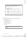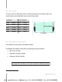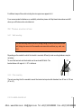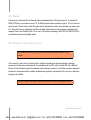
1
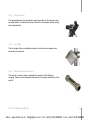
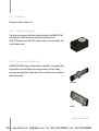
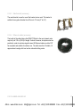
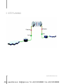
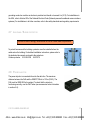
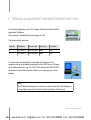
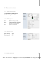
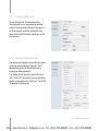
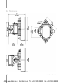
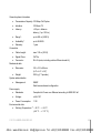
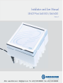
Installation and User Manual
SENCITY®Link SL60-3001/SL60-4001
Revision F
4Gon www.4Gon.co.uk [email protected] Tel: +44 (0)1245 808295 Fax: +44 (0)1245 808299
4Gon www.4Gon.co.uk [email protected] Tel: +44 (0)1245 808295 Fax: +44 (0)1245 808299
We, HUBER+SUHNER AG of Degersheimerstrasse 14, CH-9100 Herisau/Switzerland
declare that the product
SENCITY®Link / SL60-3001, SL60-4001 (formerly: SL60-100-57/64-38-E-O)
is in conformity – after consultation with the notified body Phoenix Testlab (No. 0700) – with the following
standards and normative documents:
●
EN 50371 (2002): Generic standard to demonstrate the compliance of low power electronic and
electrical apparatus with the basic restrictions related to human exposure to electromagnetic
fields (10 MHz - 300 GHz)
●
EN 55022 (2006): Information technology equipment - Radio disturbance characteristics - Limits
and methods of measurement
●
EN 55024 (1998): Information technology equipment - Immunity characteristics - Limits and
methods of measurement
●
EN 60950-1 (2006): Information technology equipment - Safety -- Part 1: General requirements
●
ETSI EN 302 217-3 (2007): Fixed Radio Systems; Characteristics and requirements for point-topoint equipment and antennas; Part 3: Harmonized EN covering essential requirements of Article
3.2 of R&TTE Directive for equipment operating in frequency bands where simplified or no
frequency co-ordination procedures are applied
●
ETSI EN 302 217-4-2 (2007): Fixed Radio Systems; Characteristics and requirements for pointto-point equipment and antennas; Part 4-2: Harmonized EN covering essential requirements of
Article 3.2 of R&TTE Directive for antennas is in accordance with the following Directives:
●
R&TTE Directive 1999/5/EC
We hereby declare that the equipment named above has been designed to comply with
the relevant sections of the above referenced specifications. The unit complies with all
essential requirements of the Directives.
Herisau, January 2008
© 2010 HUBER+SUHNER AG
3
4Gon www.4Gon.co.uk [email protected] Tel: +44 (0)1245 808295 Fax: +44 (0)1245 808299
This device complies with part 15 of the FCC rules. Operation is subject to the following two conditions:
1. This device may not cause harmful interference.
2. This device must accept any interference received, including interference that may cause
undesired operation.
If this product is suspected of causing harmful interference with other equipment, discontinue its operation
immediately and contact HUBER+SUHNER.
In order to meet FCC RF Exposure requirements, this device must be installed in such a way that a
distance of 2 m is always maintained between the device antenna and nearby persons.
Modifications or substitutions made on the terminal or parts of it without the written approval of
HUBER+SUHNER could void the user’s authority to operate the equipment.
FCC ID: TTDSL60100
IC: 6318A-SL60100
4
www.hubersuhner.com
4Gon www.4Gon.co.uk [email protected] Tel: +44 (0)1245 808295 Fax: +44 (0)1245 808299
TABLE OF CONTENTS
1 Introduction
1.1 Intended users
1.2 Revision
1.3 Prior knowledge
1.4 Organisation
1.5 Used symbols
1.6 Safety
1.7 Warranty
1.8 Copyright / Disclaimer
2 System overview
2.1 General description
2.1.1 Benefits
2.1.2 Applications
2.2 System components
2.2.1 Terminals
2.2.2 Alignment bracket
2.2.3 Alignment tool
2.2.4 Ice bridge
2.2.5 Sealed Ethernet connector
2.2.6 Accessories
2.2.6.1 PoE injector (accessory)
2.2.6.2 Data line protector (accessory)
2.2.6.3 Mast bracket (accessory)
2.2.6.4 Ethernet cables (accessory)
3 Site planning
3.1 Terminal location
3.2 Line of sight
3.3 Link distance / Link availability
3.4 Terminal mounting options
© 2010 HUBER+SUHNER AG
7
7
7
7
8
9
10
10
11
12
12
12
13
13
14
14
15
15
15
16
16
16
17
17
18
19
20
20
21
3.4.1 Wall mounting
3.4.2 Pole mounting
3.5 Cabling
3.6 Grounding / Lightning protection
3.7 Co-located applications
4 Installation
4.1 Unpacking
4.2 Mount installation
4.2.1 Wall mount
4.2.2 Mast mount
4.3 Terminal installation
4.4 Cable installation
4.5 Antenna alignment
4.5.1 Alignment Procedure
4.5.1.1 Optical alignment
4.5.1.2 Power level alignment
4.6 Grounding
4.7 Lightning / Surge protector
4.8 Power injector
5 Terminal management and monitoring functions
5.1 Web browser interface
5.1.1 System overview screen
5.1.1.1 Traffic light colors
5.1.2 Password screen
5.1.3 Firmware update screen
5.1.4 Network configuration screen
5.1.5 Radio alignment screen
5.1.6 Network statistics screen
5.1.7 SNMP configuration screen
21
21
22
22
23
24
24
25
25
26
27
27
28
29
29
30
30
31
31
32
33
33
33
33
34
34
35
35
36
5
4Gon www.4Gon.co.uk [email protected] Tel: +44 (0)1245 808295 Fax: +44 (0)1245 808299
5.2 SNMP interface
5.3 Reset-CD
5.3.1 Parameter reset
5.3.2 Firmware upload
A Technical information
A.1 Troubleshooting
A.1.1 Power and network connection
A.1.2 Network configuration
A.1.3 Duplex mismatch
A.1.4 Miss-alignment
A.2 Specifications
A.2.1 Ethernet cable colour code
A.3 Receiver level / Rain / Link distance
A.4 Availability / Rain zone / Link distance
A.4.1 Map of America
6
37
39
40
40
41
41
41
41
42
42
44
47
48
49
49
A.4.2 Map of Asia and Middle East
A.4.3 Map of Europe
A.5 Accessories order information
B Country specific information
B.1.1 Switzerland, Germany
B.1.1.1 English
B.1.1.2 Deutsch
B.1.1.3 Français
B.1.1.4 Italiano
C Contacts
C.1.1 Technical assistance
C.1.2 Service center / RMA
D Glossary
E Notes
51
53
55
58
58
58
58
59
59
60
60
60
61
62
www.hubersuhner.com
4Gon www.4Gon.co.uk [email protected] Tel: +44 (0)1245 808295 Fax: +44 (0)1245 808299
1 INTRODUCTION
1.1 INTENDED USERS
This manual is intended for all installation and service personnel who are involved in the planning,
installation, operation and maintenance of SL60-3001 / SL60-4001 equipment.
Please read the complete SL60-3001 / SL60-4001 (SENCITY®Link) manual prior
to its unpacking, installation, setup and deployment.
Although the SENCITY®Link is designed for easy installation and setup, optimum performance can be
achieved by following the procedures outlined in this manual.
1.2 REVISION
HUBER+SUHNER reserves the right to revise this documentation periodically without any obligation to
provide notification of such revision or changes. The latest revision can be downloaded on
http://www.sl60.com.
1.3 PRIOR KNOWLEDGE
This manual assumes that the installer has at least a basic experience and understanding of networking
equipment, as well as some familiarity with its configuration and operation. The information covered in this
manual should be fully understood prior to installation.
© 2010 HUBER+SUHNER AG
7
4Gon www.4Gon.co.uk [email protected] Tel: +44 (0)1245 808295 Fax: +44 (0)1245 808299
1.4 ORGANISATION
This user manual is organised into chapters as follows:
8
●
Chapter 1: Introduction – Describes general and legal information.
●
Chapter 2: System Overview – Contains the technical data and the description of the equipments.
●
Chapter 3: Site Planning – Summarizes the requirements regarding site and network. This chapter
has to be read as preparation for the installation.
●
Chapter 4: Installation – Describes the recommended installation procedure of the terminal.
●
Chapter 5: Management and monitoring functions
●
Appendix A: Presents additional useful technical information like: troubleshooting, weather maps and
technical data.
●
Appendix B: Country specific information
●
Appendix C: Contacts
●
Appendix D: Glossary – Helps with the most important abbreviations.
www.hubersuhner.com
4Gon www.4Gon.co.uk [email protected] Tel: +44 (0)1245 808295 Fax: +44 (0)1245 808299
1.5 USED SYMBOLS
Danger
Not used
Warning
Risk for human and equipment
Caution
Risk for equipment and functionality
Advice
© 2010 HUBER+SUHNER AG
9
4Gon www.4Gon.co.uk [email protected] Tel: +44 (0)1245 808295 Fax: +44 (0)1245 808299
1.6 SAFETY
The following general safety precautions must be observed during all phases of operation and service of
those products covered in this manual. Failure to comply with these precautions, or with specific warnings
elsewhere in this manual, willfully violates standards of design, manufacture and the intended use of the
product.
The SL60-3001 / SL60-4001 meets all CE and FCC electrometric radiation safety
requirements for radio equipment. However, it is advisable to avoid long-term
exposure to the front face of the terminal while operating this equipment.
Outdoor equipment must be properly grounded to provide some protection
against voltage surges and built-up static charges (as illustrated in chapters 4.6
and 4.7).
All electrical and mechanical installations must comply with local and/or national
electrical and building codes.
This equipment must not be modified. Neither must any of its component parts
be substituted.
1.7 WARRANTY
HUBER+SUHNER warrants to the original end user (purchaser) that this product is free from any defects in
materials or workmanship for a period of up to one year from the date of shipment to the end user.
During the warranty period, and upon proof of purchase, should the product show indications of failure due to
faulty workmanship and/or materials, HUBER+SUHNER will, at its discretion, repair or replace the defective
products or components without charge for either parts or labor, and to whatever extent it shall deem
10
www.hubersuhner.com
4Gon www.4Gon.co.uk [email protected] Tel: +44 (0)1245 808295 Fax: +44 (0)1245 808299
necessary to restore the product or components to full operating condition. Any replacement will consist of a
new or remanufactured, functionally equivalent product of equal value, and will be offered solely at the
discretion of HUBER+SUHNER.
This warranty shall not apply if the product is modified (e.g. warranty seal is broken), misused, tampered
with, damaged by an act of God, or subjected to abnormal working conditions.
To obtain services under this warranty, contact HUBER+SUHNER‘s Service Center, referring to your Return
Material Authorization number (see C.1.2). Products must be returned Postage Prepaid. It is recommended
that the terminal be insured when shipped. Any products returned without either proof of purchase or with an
outdated warranty will be repaired or replaced and the customer will be billed for parts and labor. All repaired
or replaced products will be shipped by HUBER+SUHNER to the corresponding return address ‘Postage
Paid’ (USA only). If the customer specifies some other return destination beyond US borders, the customer
shall bear the cost of the return shipment. This warranty gives you specific legal rights, and you may also
have other rights that vary from state to state.
1.8 COPYRIGHT / DISCLAIMER
Copyright © 2010 by HUBER+SUHNER
The contents of this publication may not be reproduced in any part or as a whole, transcribed, stored in a
retrieval system, translated into any language, or transmitted in any form or by any means, electronic,
mechanical, magnetic, optical, chemical, photocopying, manual, or otherwise, without the prior written
permission of HUBER+SUHNER.
© 2010 HUBER+SUHNER AG
11
4Gon www.4Gon.co.uk [email protected] Tel: +44 (0)1245 808295 Fax: +44 (0)1245 808299
2 SYSTEM OVERVIEW
2.1 GENERAL DESCRIPTION
The SL60-3001 / SL60-4001 system operates as a data link in the
unlicensed 60 GHz band between 57 GHz and 64 GHz and delivers a full
duplex data rate of 100 Mbps over a distance of up to 800 m (2600 ft).
Measuring only 16 cm × 16 cm (6.3“ × 6.3“), the terminal’s compact size is
attained by extensively integrating the active and passive components.
For more detailed technical data see appendix A.2.
2.1.1 Benefits
12
●
Easy installation – The concept of the
SENCITY®Link allows to the end user to
install it as easy as any other network
component.
The single cable solution reduces the
complexity of the installation. The terminal
is connected to the network, monitored
and supplied with power through a single
outdoor rated CAT 5e Ethernet cable.
The visual alignment tool and an alignment
bracket allows the user to easily install the
link.
Immediate operation without the need of additional configuration is granted.
●
Network performance – Guaranteed full duplex 100 Mbps along the complete range. Unlike typical
WLAN equipment the user can transmit a full 100 Mbps over the link.
www.hubersuhner.com
4Gon www.4Gon.co.uk [email protected] Tel: +44 (0)1245 808295 Fax: +44 (0)1245 808299
●
License free operation – The system has been approved and can be operated in many countries.
●
System administration – To monitor the status and the traffic the user can access the link statistics
either via the HTML user interface or by integrating it into a network management tool via SNMP.
●
Security – The proprietary radio interface does not allow any other system to access the 60 GHz
transmitted data.
A high level of data security is inherent in the product via signal absorption by atmospheric oxygen
and the use of high gain/narrow beam width antennas.
2.1.2 Applications
●
LAN extension
●
Redundant access
●
Campus connectivity
●
Disaster recovery
●
Wireless backhaul
●
Centralization of IT infrastructure
●
Temporary connections during events
●
Mesh and hub and spoke configuration
2.2 SYSTEM COMPONENTS
The SL60-3001 / SL60-4001 system is composed of the following components:
●
Terminal A and Terminal B
●
Alignment bracket
●
Alignment tool
●
Ice bridge
© 2010 HUBER+SUHNER AG
13
4Gon www.4Gon.co.uk [email protected] Tel: +44 (0)1245 808295 Fax: +44 (0)1245 808299
●
Sealed Ethernet connection
●
Main accessories:
○
PoE injector
○
Lightning protector
○
Mast bracket
○
Ethernet cables
2.2.1 Terminals
The terminals are the main system components. They combine the antenna,
transmitter and receiver and are connected to the network via a standard
Ethernet cable with RJ-45 connector.
Power is supplied through the Ethernet cable to the terminal. This will require
either a PoE (802.3af) compatible network equipment or an additional PoE
injector.
2.2.2 Alignment bracket
The alignment bracket facilitates installation and positioning owing to its
independent axis with coarse and fine alignment capabilities.
14
www.hubersuhner.com
4Gon www.4Gon.co.uk [email protected] Tel: +44 (0)1245 808295 Fax: +44 (0)1245 808299
2.2.3 Alignment tool
The optical alignment tool provided is easily mounted on the terminal using
an elastic band. It enables both ends of the link to be aligned quickly, simply
and independently.
2.2.4 Ice bridge
The ice bridge offers an additional protection for the terminal against rain,
snow and ice-formation.
2.2.5 Sealed Ethernet connector
The seal kit is used to make a watertight connection of the Ethernet
coupling. Please use the separate instructions for a proper installation of the
seal kit.
© 2010 HUBER+SUHNER AG
15
4Gon www.4Gon.co.uk [email protected] Tel: +44 (0)1245 808295 Fax: +44 (0)1245 808299
2.2.6 Accessories
Please also refer to section A.5.
2.2.6.1
PoE injector (accessory)
The terminal is powered via Ethernet cable according to the IEEE 802.3af
PoE standard. Should the network equipment connected to the
SENCITY®Link does not offer PoE, a power injector can be inserted in line
to the Ethernet cable.
2.2.6.2
Data line protector (accessory)
HUBER+SUHNER strongly recommends the installation of an outdoor data
line protector to provide lightning and surge protection for the building,
personnel and equipment. Please refer to the local and/or national electrical
and building codes.
Outdoor
Indoor
16
www.hubersuhner.com
4Gon www.4Gon.co.uk [email protected] Tel: +44 (0)1245 808295 Fax: +44 (0)1245 808299
2.2.6.3
Mast bracket (accessory)
The mast bracket is used to mount the bracket onto a mast. The bracket is
suitable for any pole diameter from 50 mm to 115 mm (2” to 4,5”).
2.2.6.4
Ethernet cables (accessory)
The length of the cable linking the SENCITY®Link to the next network node
may be up to 100 m (328 ft) in length. It should, however, be kept as short as
practical in order to minimize signal losses. All Ethernet cables must be CAT
5e compliant and suitable for outdoor use. The cable must be UV stable, UL
approved and comply with local and/or national building codes.
© 2010 HUBER+SUHNER AG
17
4Gon www.4Gon.co.uk [email protected] Tel: +44 (0)1245 808295 Fax: +44 (0)1245 808299
3 SITE PLANNING
Protector
PoE
18
Protector
PoE
www.hubersuhner.com
4Gon www.4Gon.co.uk [email protected] Tel: +44 (0)1245 808295 Fax: +44 (0)1245 808299
All installers must perform a full site inspection and plan carefully prior to the
physical installation of an SL60-3001 / SL60-4001 system.
This preparation must include:
●
Evaluating the most appropriate location for the installation of the
terminal.
●
Identifying an appropriate mounting structure (wall or mast) for each
terminal.
●
Planning the cable routing from the network component to the terminal.
3.1 TERMINAL LOCATION
When selecting the best terminal location the following factors should be considered:
●
Accessibility (e.g. roof)
●
Type of mounting (e.g. wall or pole)
●
Grounding connection point
●
Cable runs (max. 100 m / 328 ft)
●
Line of sight
Use of given protection against sun, rain, etc. will increase the equipment
performance.
© 2010 HUBER+SUHNER AG
19
4Gon www.4Gon.co.uk [email protected] Tel: +44 (0)1245 808295 Fax: +44 (0)1245 808299
3.2 LINE OF SIGHT
To ensure a clear line of sight, there must be no obstructions between the two terminal locations. The
required clearance can be established visually using the following table 1:
Link distance
Boundary diameter
100 m
(328 ft)
0.7 m
(2.3 ft)
200 m
(656 ft)
1.0 m
(3.3 ft)
400 m
(1312 ft)
1.4 m
(4.6 ft)
600 m
(1968 ft)
1.7 m
(5.6 ft)
800 m
(2625 ft)
2.0 m
(6.6 ft)
Boundary diameter
Link distance
3.3 LINK DISTANCE / LINK AVAILABILITY
The link distance is directly related to the weather conditions.
The affordable link availability is influenced by the following environmental conditions:
●
Rain: the less, the better
●
Temperature: the higher, the better
●
Air pressure: the lower, the better
Knowledge of the link distance (line of sight) is important in estimating link quality.
1
Fresnel zone calculation
20
www.hubersuhner.com
4Gon www.4Gon.co.uk [email protected] Tel: +44 (0)1245 808295 Fax: +44 (0)1245 808299
For different maps of the world including the rain regions see appendix A.4.
For a more accurate link distance vs. availability calculation please visit http://www.hubersuhner.com/sl60
where you will find an online calculation tool.
3.4 TERMINAL MOUNTING OPTIONS
3.4.1 Wall mounting
The wall mounting location should be strong enough to secure the terminal to the
wall, taking into account all foreseeable environmental conditions (e.g. wind, rain,
ice).
Depending on the material to which the bracket is mounted, differently sized mounting hardware may be
necessary.
50°
To mount the terminal onto the bracket use the enclosed M6 bolts. The
bracket allows a tilt angle of +/- 50° in both axis.
3.4.2 Pole mounting
The pole mounting kit will be needed to mount the terminal onto poles with diameters from 50 mm to 115 mm
(2” to 4,5”).
© 2010 HUBER+SUHNER AG
21
4Gon www.4Gon.co.uk [email protected] Tel: +44 (0)1245 808295 Fax: +44 (0)1245 808299
3.5 CABLING
The terminal is delivered with an Ethernet cable terminated with a RJ-45 plug connector. To connect the
SENCITY®Link to your network, use a CAT 5e Ethernet cable with a maximum length of 100 m to the next
network node. Please verify too that the cable used is designed for outdoor environments (e.g. water, solar
UV). Since the power is supplied by the Ethernet cable, please make sure that network equipment used
supports Power over Ethernet (PoE). If not, use a PoE injector according to IEEE 802.3af. SENCITY®Link
can handle crossover and straight cables.
3.6 GROUNDING / LIGHTNING PROTECTION
The terminal must be properly grounded to provide protection against voltage
surges.
In the event of a short circuit or lightning strike, effective grounding can prevent damage to building,
equipment, infrastructure and personnel. For installations in the USA, refer to Article 830 of the National
Electrical Code (Network-powered broadband communications systems), for all other countries, implement
protection in accordance with the safety standards and regulatory requirements of the country in which the
equipment is installed.
HUBER+SUHNER strongly recommends the use of outdoor lightning protectors.
22
www.hubersuhner.com
4Gon www.4Gon.co.uk [email protected] Tel: +44 (0)1245 808295 Fax: +44 (0)1245 808299
3.7 CO-LOCATED APPLICATIONS
Owing to the compact size of the SL60-3001 / SL60-4001 integrated terminal, it is particularly suitable for cosited applications. Possible configurations include:
●
Back-to-back - e.g. doubles the link distance
●
Parallel link - doubles data capacity or redundancy
●
Star - hub and spoke
To deploy a co-sited application, please contact HUBER+SUHNER to assist with devising an appropriate site
design.
© 2010 HUBER+SUHNER AG
23
4Gon www.4Gon.co.uk [email protected] Tel: +44 (0)1245 808295 Fax: +44 (0)1245 808299
4 INSTALLATION
Owing to the small size and integrated design of the SENCITY®Link, its correct installation and setup is
relatively simple.
Nevertheless, when working on a roof, ladder, mast or staging, please take
extreme care, observing all facility and OSHA (or other applicable regulatory
agency) required safety precautions.
4.1 UNPACKING
All equipment and installation material is packed
into one box. This is divided into three cartons
containing the following items:
●
●
●
24
Carton A:
○
Terminal A
○
Bracket
○
Mounting set
Carton B:
○
Terminal B
○
Bracket
○
Mounting set
Carton C:
○
Manual
○
Reset-CD
www.hubersuhner.com
4Gon www.4Gon.co.uk [email protected] Tel: +44 (0)1245 808295 Fax: +44 (0)1245 808299
●
○
Ice bridges
○
Accessories
Required tools:
○
Adjustable-end wrench
4.2 MOUNT INSTALLATION
4.2.1 Wall mount
The wall and mounting screws must be able to support a weight of 11 pounds (5
kg), taking into account associated wind and potential ice loading factors.
To ensure the use of the correct screws for the installation, HUBER+SUHNER
recommends consulting HILTI’s online Anchor System Advisor at
http://www.us.hilti.com/holus/modules/adansel/adas_oview.jsp
Right
© 2010 HUBER+SUHNER AG
Wrong
25
4Gon www.4Gon.co.uk [email protected] Tel: +44 (0)1245 808295 Fax: +44 (0)1245 808299
4.2.2 Mast mount
●
Ensure that the mast used has a diameter of between 50 mm to 115
mm (2” to 4.5”).
●
Use a 13 mm flat wrench (~½”) to fasten the M8 screw nut.
●
Fasten the alignment bracket onto front part of mast bracket using
the enclosed stainless steel screws, nuts and washer (M6).
●
Fix the front part of the mast bracket and the attached alignment
bracket on the mast.
Do not use zinc plated screws as these will corrode and endanger link
performance and environment.
26
www.hubersuhner.com
4Gon www.4Gon.co.uk [email protected] Tel: +44 (0)1245 808295 Fax: +44 (0)1245 808299
4.3 TERMINAL INSTALLATION
It is important to install the terminal on the bracket
with the same orientation (i.e. antenna polarization)
at both ends of the link. The terminal must be
mounted on the bracket in such a way that the
cable enters it on the same side, top or bottom.
The terminal must be mounted on the bracket by
using the allen key with the enclosed stainless
steel screws (M6 x 12).
Right
Wrong
Right
Right
Do not use zinc plated screws as these will corrode and endanger link
performance and environment.
Positioning the terminal with lateral cable entry will influence heat dissipation.
4.4 CABLE INSTALLATION
The length of the cable from the terminal to the next network component
may be up to 100 m (328 ft) in length, but should be kept as short as
practical in order to reduce signal loss. All Ethernet cables must be CAT 5e
compliant and suitable for outdoor use. The cable must be UV stable, UL
approved and must comply with local and/or national building codes.
© 2010 HUBER+SUHNER AG
27
4Gon www.4Gon.co.uk [email protected] Tel: +44 (0)1245 808295 Fax: +44 (0)1245 808299
To enter the building, HUBER+SUHNER recommends using cable seals from
Roxtec (http://www.roxtec.com).
4.5 ANTENNA ALIGNMENT
One of SENCITY®Link’s biggest advantage is its fast, easy alignment procedure.
The terminals can be aligned optically by using the alignment tool. No electrical alignment is required,
although possible.
The table below shows the alignment tolerance:
Link distance
Alignment
accuracy
100 m
328 ft
0.9 m
400 m
1312 ft 3.5 m
11.5 ft
600 m
1968 ft 5.2 m
17.2 ft
800 m
2625 ft 7.0 m
22.9 ft
28
2.9 ft
Alignment accuracy
nc e
is t a
d
k
Lin
www.hubersuhner.com
4Gon www.4Gon.co.uk [email protected] Tel: +44 (0)1245 808295 Fax: +44 (0)1245 808299
4.5.1 Alignment Procedure
The following procedure achieves fast, accurate alignment (for all operations, the enclosed 5 mm allen key
can be used):
4.5.1.1
Optical alignment
a) Place the alignment tool to the most accessible corner
and ensure good visibility to the opposite terminal by
rotating the telescope.
b) Loosen the horizontal lock screws (labeled “3”)
c) Place the horizontal axis course screw in its middle
position (needle).
d) Carry out a rough alignment on the horizontal axis and
fasten the screw (labeled “1”).
e) Repeat steps b), c) and d) for the vertical
axis.
Horizontal alignment
Wall
f)
Turn the horizontal course screw (labeled
“2”) by viewing through the telescope and
Vertical alignment
carrying out the fine alignment.
g) Repeat e) for the vertical axis.
h) If necessary, repeat the fine alignment procedure e) for both axes until the opposite link is correctly
aligned.
i) Fasten the lock screw (labeled “3”) on both
horizontal and vertical axes.
2 Fine alignment
1 Coarse alignment
3 First lock
© 2010 HUBER+SUHNER AG
29
4Gon www.4Gon.co.uk [email protected] Tel: +44 (0)1245 808295 Fax: +44 (0)1245 808299
4.5.1.2
Power level alignment
Optionally (but recommended), an alignment
based on the receiver power level of each terminal
can be done. The power level can be accessed via
the web interface (see section 5.1.5).
As described in section 4.5.1.1, it is recommended
to proceed first with a rough horizontal
(respectively vertical) alignment and then to do a
fine alignment on each axis. Do not forget to
loosen (respectively tighten) the two lock screws
before (respectively afterwards).
See chapter A.3 for an estimation of the power
levels at different rain rates and link distances.
A power level of -60dBm is better than a power level of -70dBm
4.6 GROUNDING
The terminal must be properly grounded.
Two screws are provided on the reverse housing of
the terminal to facilitate the correct grounding. To
fasten the grounding cable onto the terminal, use a
lug and serrated washer combined with an M8 nut.
Connect the terminal to the connection points
nearest to the building-to-earth ground point. The
30
Grounding screws
www.hubersuhner.com
4Gon www.4Gon.co.uk [email protected] Tel: +44 (0)1245 808295 Fax: +44 (0)1245 808299
grounding conductor must be as short as is practical and should not exceed 6 m (20 ft). For installations in
the USA, refer to Articles 830 of the National Electrical Code (Network-powered broadband communications
systems). For installations in all other countries, refer to the safety standards and regulatory requirements.
4.7 LIGHTNING / SURGE PROTECTOR
HUBER+SUHNER strongly recommends the use of outdoor data line protectors.
To protect humans and the building a protector must be installed before the
cable enters the building. For detailed installation instructions, please refer to
the dedicated documents enclosed to the protectors:
Outdoor protector 3414.99.0008 84016716
4.8 POWER INJECTOR
The power injector is connected inline into the data line. The maximum
distance between the PoE and the SENCITY®Link is 100 m (328 ft). The
PoE must be IEEE 802.3af compliant. To check that the injector is
functioning correctly, use the PoE Tester (see accessories order information
in section A.5).
© 2010 HUBER+SUHNER AG
31
4Gon www.4Gon.co.uk [email protected] Tel: +44 (0)1245 808295 Fax: +44 (0)1245 808299
5 TERMINAL MANAGEMENT AND MONITORING FUNCTIONS
For an initial configuration, use a PC or laptop. Address the terminal with the
appropriate IP address.
Every terminal is labeled with its terminal type (A or B).
The factory default values are:
Terminal
IP address
Subnet mask
User name
Password
A
192.168.0.11
255.255.255.0 admin
sl60
B
192.168.0.12
255.255.255.0 admin
sl60
To communicate with the terminal, ensure that the IP address of the
computer used is not allocated automatically by the DHCP server. Configure
the IP address manually - e.g. 192.168.0.1 with subnet mask 255.255.255.0.
Remember to ensure that your web browser is not using any proxy server
settings.
Note:
The IP address settings have no influence on data connectivity. This settings are
only needed to access the terminal monitoring functions of the terminal.
32
www.hubersuhner.com
4Gon www.4Gon.co.uk [email protected] Tel: +44 (0)1245 808295 Fax: +44 (0)1245 808299
5.1 WEB BROWSER INTERFACE
5.1.1 System overview screen
This screen shows an overview of key link
information including its current status.
5.1.1.1
Green:
Yellow:
Red:
Traffic light colors
System is working correctly
System is working with intermittent
detection and synchronization
System is not functional
5.1.2 Password screen
Default user name:
Default password:
admin
sl60
© 2010 HUBER+SUHNER AG
33
4Gon www.4Gon.co.uk [email protected] Tel: +44 (0)1245 808295 Fax: +44 (0)1245 808299
5.1.3 Firmware update screen
Current firmware can be downloaded from
http://www.sl60.com or requested via technical
support. The downloaded file should be saved on
the local computer and then uploaded to each
terminal through the firmware update form on the
web interface.
5.1.4 Network configuration screen
The network configuration screen offers the option
to change network settings if required. The IP
address settings and VLAN settings have no
influence on data connectivity.
The “Enable VLAN” check box allows the SL603001 / SL60-4001 terminals to be accessed when
the link is integrated into a VLAN trunk. The VLAN
ID needs to be set then too.
34
www.hubersuhner.com
4Gon www.4Gon.co.uk [email protected] Tel: +44 (0)1245 808295 Fax: +44 (0)1245 808299
5.1.5 Radio alignment screen
The radio alignment screen shows specific details
relating to the alignment of the two terminals.
The radio history file does log (once a minute) the
following parameter values for the last 48 hours:
●
Time since last reboot
Time format: <days>.<hours>:<minutes>
●
Receive power at time XY ("minus" sign
omitted)
●
Device temperature in °C
●
Lock detector: if unequal to 1, then the receivers are not locked
The resynchronization button can be used to restart the synchronization process with the far end terminal.
5.1.6 Network statistics screen
The network statistics screen shows standardized
information relating to network traffic and errors.
Traffic status information is continuously updated
and specific network errors are listed.
© 2010 HUBER+SUHNER AG
35
4Gon www.4Gon.co.uk [email protected] Tel: +44 (0)1245 808295 Fax: +44 (0)1245 808299
5.1.7 SNMP configuration screen
The SL60-3001 / SL60-4001 terminal can be
integrated into a network management system by
using the implemented SNMP agent. This agent
supports GET and TRAP functionality. No setting
can be performed via SNMP.
Note:
To use this feature you need an SNMP manager program such as HP OpenView
or Castlerock’s SNMPc.
The MIB file can be downloaded directly from the terminal.
36
www.hubersuhner.com
4Gon www.4Gon.co.uk [email protected] Tel: +44 (0)1245 808295 Fax: +44 (0)1245 808299
5.2 SNMP INTERFACE
Object
OID
OID type
Description
MIB-2
(iso.org.dod.internet.mgmt.mib-2.system.x / .1.3.6.1.2.1.1.x)
sysDescr
.1.
DisplayString
Includes serial no.
sysUpTime
.3.
TimeTicks
Uptime of the network management
sysName
.5.
DisplayString
set in the web GUI
sysLocation
.6.
DisplayString
set in the web GUI
HUBERSUHNER-MIB sencity
(.iso.org.dod.internet.private.enterprises.hubersuhnerOID.sencity.x / .1.3.6.1.4.1.25358.1.x)
sencityLinkQuality
.1.
Integer
1: Green
2: Yellow
3: Red
sencityReceivePower
.10.
Integer
Receive signal level [dBm]
sencityTemperature
.11.
Integer
Temperature [°C]
sencityLockDetector
.12.
Integer
Lock detection signal level
sencityIfEthernetIn
.15.
Integer
Total frames received on the Ethernet
interface over a period of 10 seconds.
sencityIfEthernetOut
.16.
Integer
Total frames sent on the Ethernet interface
over a period of 10 seconds.
sencityIfEthernetInError
.17.
Integer
Total frames dropped due to errors received
on the Ethernet interface over a period of
10 seconds.
sencityIfAirIn
.18.
Integer
Total frames received on the Air interface
over a period of 10 seconds.
© 2010 HUBER+SUHNER AG
37
4Gon www.4Gon.co.uk [email protected] Tel: +44 (0)1245 808295 Fax: +44 (0)1245 808299
Object
OID
OID type
Description
sencityIfAirOut
.19.
Integer
Total frames sent on the Air interface over a
period of 10 seconds.
sencityIfAirInError
.20.
Integer
Total frames dropped due to errors received
on the Air interface over a period of 10
seconds.
sencityFirmwareversion
.21.
String
Installed firmware version
HUBERSUHNER-MIB sencitytraps
(.iso.org.dod.internet.private.enterprises.hubersuhnerOID.sencity.sencityTraps.x / .1.3.6.1.4.1.25358.1.22.x)
sencityLinkQualityImprovedTrap .1.
Integer
1: from red to green
2: from red to orange
3: from orange to green
sencityLinkQualityReducedTrap
.2.
Integer
1: from green to orange
2: from green to red
3: from orange to red
sencityTemperatureHighTrap
.3.
Integer
A trap indicating that the temperature within
the terminal is over or below 70 degree
Celcius
sencityTemperatureLowTrap
.4.
Integer
A trap indicating that the temperature within
the unit is over or below -40 degree Celcius
38
www.hubersuhner.com
4Gon www.4Gon.co.uk [email protected] Tel: +44 (0)1245 808295 Fax: +44 (0)1245 808299
5.3 RESET-CD
On the Reset-CD following functions are available
●
Parameter reset
●
Firmware upload
●
Documents in PDF format
This CD can be indispensable if the terminal IP address is lost or the terminal is on DHCP modus in a
network where no DHCP server is available. In those cases, even though the data transmission is not
influenced, the terminal monitoring functions are not accessible.
By using the parameter reset functionality it is possible to reset the terminal to the factory default IP
addresses (see 5). Also, if username and/or password are lost, they can be reset using the parameter reset
function (see section 5.3.1) of the CD.
This CD can be indispensable if during the firmware upload process it occurs a power breakdown or the
Ethernet connection breaks. Then it will be needed to upload the firmware via Reset-CD to the terminal.
The Reset-CD is bootable, this means the computer is started by putting the Reset-CD into the optical drive
(NOTE: the optical drive has to be defined on the computer firmware settings as a bootable device). With the
CD a Linux operating system is loaded into the computer memory, so that the communication with the
embedded linux of the terminal is enabled.
System requirements:
Intel compatible CPU (i486 or later), 32 MB RAM, CD-ROM drive as bootable
device, Ethernet interface.
© 2010 HUBER+SUHNER AG
39
4Gon www.4Gon.co.uk [email protected] Tel: +44 (0)1245 808295 Fax: +44 (0)1245 808299
5.3.1 Parameter reset
The parameter reset function will reset all terminal
parameters (e.g. IP address, username, password)
to the factory defaults.
5.3.2 Firmware upload
With the firmware upload functionality a firmware
can be uploaded to the terminal even the previous
installed firmware is lost by power breakdown or
Ethernet connectivity break during firmware upload
process.
The CD contains useful documents (manual, installation video, etc.)
40
www.hubersuhner.com
4Gon www.4Gon.co.uk [email protected] Tel: +44 (0)1245 808295 Fax: +44 (0)1245 808299
A TECHNICAL INFORMATION
A.1 TROUBLESHOOTING
This chapter provides solutions to problems that can occur during the installation and operation of the SL603001 / SL60-4001. It covers various aspects of installation and network setup.
Note:
Each of the following points must be checked at both ends of the link. Start by
performing the entire procedure on one side (e.g. Terminal A). If this does not
solve the problem, repeat all the steps at the opposite terminal.
A.1.1 Power and network connection
You must verify that the terminal is connected to the power. The PoE injector must be installed and plugged
in. Go to the terminal, disconnect the RJ-45 connector and verify if there is power in the cable using a
standard PoE tester.
Take the cable and plug it into a notebook or a network testing device and verify if there is a correct network
connection.
If there is any problem, please replace the cable and validate the connection again. We provide special,
preassembled outdoor CAT 5e cables to ensure easy installation.
A.1.2 Network configuration
Check that the IP address is in the same range and subnet as the SL60-3001 / SL60-4001.
© 2010 HUBER+SUHNER AG
41
4Gon www.4Gon.co.uk [email protected] Tel: +44 (0)1245 808295 Fax: +44 (0)1245 808299
Note:
The IP address of the SL60-3001 / SL60-4001 is 192.168.0.11 for Terminal A and
192.168.0.12 for Terminal B. All the computers on the network must have a
unique IP address in the same range, e.g. 192.168.0.X. Any computers with
identical IP addresses will not be visible on the network.
They must all, therefore, have the same subnet mask e.g. 255.255.255.0.
Do a Ping test to make sure that the SL60-3001 /
SL60-4001 is responding. Go to Start → Run →
Type “Command” → Type “ping 192.168.0.X”.
A successful Ping test will generate four replies.
As soon as the network configuration is correct you
can access the GUI (Graphical User Interface) and
check the settings according to section 4.9.
A.1.3 Duplex mismatch
If you encounter bad network performance, you probably have a duplex mismatch.
To ensure that the SL60-3001 / SL60-4001 terminal and the connected network component (e.g. switch) do
not have a duplex mismatch you must first check your statistics.
If you find many input errors, you are on the full-duplex side; if you see many late collisions, you are on the
half-duplex side.
To solve the duplex mismatch, you must manually configure both network components to the same values.
A.1.4 Miss-alignment
See the configuration interface as described in section 5.1.4. On the Radio alignment screen (see section
5.1.5) you see the signal strength in dBm (e.g. -30 dBm). If the value is below -95 dBm the receiver is not in
the correct position to track the signal. You therefore need to re-align the terminal to its opposite terminal
42
www.hubersuhner.com
4Gon www.4Gon.co.uk [email protected] Tel: +44 (0)1245 808295 Fax: +44 (0)1245 808299
(please follow the instructions in section 4.5.1).
© 2010 HUBER+SUHNER AG
43
4Gon www.4Gon.co.uk [email protected] Tel: +44 (0)1245 808295 Fax: +44 (0)1245 808299
A.2 SPECIFICATIONS
44
www.hubersuhner.com
4Gon www.4Gon.co.uk [email protected] Tel: +44 (0)1245 808295 Fax: +44 (0)1245 808299
General system information
●
Transmission Capacity: 100 Mbps Full Duplex
●
Interface:
100 Base-TX
●
Latency:
< 50 µs + distance
latency (1 µs / 300 m)
●
Range*:
up to 800 m (2600 ft)
●
Availability*:
up to 99.999%
●
Warranty:
Connection
1 year
●
Cable Length:
max. 100 m (300 ft)
●
Signal Wires:
CAT 5e
●
Connector:
Mechanical data
●
Dimension:
●
Weight:
System administration
●
Management:
RJ–45 (male; including outdoor Ethernet seal kit)
162 x 162 x 89 mm
(6.4“ x 6.4“ x 3.5“)
3500 g (7.7 pounds)
SNMP
Web browser-based configuration
Power supply
●
Standards:
Compliant to Power over Ethernet according to IEEE 802.3af
●
Voltage:
± 48 V DC
●
Power Consumption:
Environmental data
●
11 W
Working Temperature **: - 45 °C ... + 55 °C
(- 49 °F … + 131 °F)
© 2010 HUBER+SUHNER AG
45
4Gon www.4Gon.co.uk [email protected] Tel: +44 (0)1245 808295 Fax: +44 (0)1245 808299
●
Storage Temperature: - 30 °C … + 55 °C
(- 22 °F … + 131 °F)
●
Wind Load:
operating
survival
160 km/h (100 mph)
200 km/h (125 mph)
Regulatory
●
Regulatory Compliance:
FCC Part 15
Industry Canada RSS210
R&TTE Directive 1999/5/EC
Ordering information
●
SL60-3001: Item # 84057630
SL60-4001: Item # 84064720
each composed of:
2 Terminals
2 Alignment brackets
1 Manual
2 Mounting sets
1 Reset-CD
2 Ice bridges
* The range depends on the climate zone and the requested availability
** Only if the terminal is powered up
46
www.hubersuhner.com
4Gon www.4Gon.co.uk [email protected] Tel: +44 (0)1245 808295 Fax: +44 (0)1245 808299
A.2.1 Ethernet cable colour code
Note:
By cutting of the connector the warranty will expire.
Pin
Name
RJ45 Plug
1
TX+
Black
2
TX-
Green
3
RX+
Red
4
Power+
Blue
5
Power+
White
6
RX-
Orange
7
Power-
Yellow
8
Power-
Brown
Twisted pairs:
●
Black / Green
●
Yellow / Brown
●
Red / Orange
●
Blue / White
© 2010 HUBER+SUHNER AG
47
4Gon www.4Gon.co.uk [email protected] Tel: +44 (0)1245 808295 Fax: +44 (0)1245 808299
A.3 RECEIVER LEVEL / RAIN / LINK DISTANCE
The following diagram shows the approximate receiver levels at different rain rates and distances. This
diagram is valid for A and B terminals delivered with firmware version 1.40 or higher.
SL60-3001
SL60-4001
48
www.hubersuhner.com
4Gon www.4Gon.co.uk [email protected] Tel: +44 (0)1245 808295 Fax: +44 (0)1245 808299
A.4 AVAILABILITY / RAIN ZONE / LINK DISTANCE
A.4.1 Map of America
© 2010 HUBER+SUHNER AG
49
4Gon www.4Gon.co.uk [email protected] Tel: +44 (0)1245 808295 Fax: +44 (0)1245 808299
The link distance is directly related to the weather conditions. The tables below refer to a link working at a
distance of up to 600m (SL60-3001) resp. 800m (SL60-4001), for dry weather conditions.
600m (SL60-3001):
Availability
Rain zone *
Link distance (m)
A
B
C
D
E
F
G
H
J
K
L
M
N
P
Q
99%
598
593
591
576
592
580
569
577
534
582
577
561
554
512
463
99.9%
577
569
554
534
547
534
512
523
477
512
498
470
429
366
355
99.99%
534
512
498
481
470
450
443
438
429
412
375
370
325
278
304
99.999%
470
438
412
412
358
346
366
340
384
319
274
299
255
221
261
800m (SL60-4001):
Availability
Rain zone *
Link distance (m)
A
B
C
D
E
F
G
H
J
K
L
M
N
P
Q
99%
797
789
785
764
787
770
752
765
701
772
765
741
730
669
597
99.9%
765
752
730
701
719
701
669
684
618
669
648
607
549
461
446
99.99%
701
669
648
624
607
578
569
561
549
524
473
466
405
343
376
99.999%
607
561
524
524
450
434
461
425
486
397
338
370
312
268
320
* Rain zone according to ITU-R Recommendation PN.837-1
99.9% availability equates to 526 minutes per year of outage due to heavy rains.
99.99% availability equates to 53 minutes per year of outage due to heavy rains.
99.999% availability equates to 5 minutes per year of outage due to heavy rains.
50
www.hubersuhner.com
4Gon www.4Gon.co.uk [email protected] Tel: +44 (0)1245 808295 Fax: +44 (0)1245 808299
A.4.2 Map of Asia and Middle East
© 2010 HUBER+SUHNER AG
51
4Gon www.4Gon.co.uk [email protected] Tel: +44 (0)1245 808295 Fax: +44 (0)1245 808299
The link distance is directly related to the weather conditions. The tables below refer to a link working at a
distance of up to 600m (SL60-3001) resp. 800m (SL60-4001), for dry weather conditions.
600m (SL60-3001):
Availability
Rain zone *
Link distance (m)
A
B
C
D
E
F
G
H
J
K
L
M
N
P
Q
99%
598
593
591
576
592
580
569
577
534
582
577
561
554
512
463
99.9%
577
569
554
534
547
534
512
523
477
512
498
470
429
366
355
99.99%
534
512
498
481
470
450
443
438
429
412
375
370
325
278
304
99.999%
470
438
412
412
358
346
366
340
384
319
274
299
255
221
261
800m (SL60-4001):
Availability
Rain zone *
Link distance (m)
A
B
C
D
E
F
G
H
J
K
L
M
N
P
Q
99%
797
789
785
764
787
770
752
765
701
772
765
741
730
669
597
99.9%
765
752
730
701
719
701
669
684
618
669
648
607
549
461
446
99.99%
701
669
648
624
607
578
569
561
549
524
473
466
405
343
376
99.999%
607
561
524
524
450
434
461
425
486
397
338
370
312
268
320
* Rain zone according to ITU-R Recommendation PN.837-1
99.9% availability equates to 526 minutes per year of outage due to heavy rains.
99.99% availability equates to 53 minutes per year of outage due to heavy rains.
99.999% availability equates to 5 minutes per year of outage due to heavy rains.
52
www.hubersuhner.com
4Gon www.4Gon.co.uk [email protected] Tel: +44 (0)1245 808295 Fax: +44 (0)1245 808299
A.4.3 Map of Europe
© 2010 HUBER+SUHNER AG
53
4Gon www.4Gon.co.uk [email protected] Tel: +44 (0)1245 808295 Fax: +44 (0)1245 808299
The link distance is directly related to the weather conditions. The tables below refer to a link working at a
distance of up to 600m (SL60-3001) resp. 800m (SL60-4001), for dry weather conditions.
600m (SL60-3001):
Availability
Rain zone *
Link distance (m)
A
B
C
D
E
F
G
H
J
K
L
M
N
P
Q
99%
598
593
591
576
592
580
569
577
534
582
577
561
554
512
463
99.9%
577
569
554
534
547
534
512
523
477
512
498
470
429
366
355
99.99%
534
512
498
481
470
450
443
438
429
412
375
370
325
278
304
99.999%
470
438
412
412
358
346
366
340
384
319
274
299
255
221
261
800m (SL60-4001):
Availability
Rain zone *
Link distance (m)
A
B
C
D
E
F
G
H
J
K
L
M
N
P
Q
99%
797
789
785
764
787
770
752
765
701
772
765
741
730
669
597
99.9%
765
752
730
701
719
701
669
684
618
669
648
607
549
461
446
99.99%
701
669
648
624
607
578
569
561
549
524
473
466
405
343
376
99.999%
607
561
524
524
450
434
461
425
486
397
338
370
312
268
320
* Rain zone according to ITU-R Recommendation PN.837-1
99.9% availability equates to 526 minutes per year of outage due to heavy rains.
99.99% availability equates to 53 minutes per year of outage due to heavy rains.
99.999% availability equates to 5 minutes per year of outage due to heavy rains.
54
www.hubersuhner.com
4Gon www.4Gon.co.uk [email protected] Tel: +44 (0)1245 808295 Fax: +44 (0)1245 808299
A.5 ACCESSORIES ORDER INFORMATION
Item number
Description
23033695
Data Line Protector (indoor)
To use only in combination with an
outdoor protector.
84014284
Data Line Protector (outdoor)
84021330
PoE 802.3af Tester
© 2010 HUBER+SUHNER AG
55
4Gon www.4Gon.co.uk [email protected] Tel: +44 (0)1245 808295 Fax: +44 (0)1245 808299
Item number
Description
84021333
PoE 802.3af Power Injector
84016575
SENCITY®Link Alignment Bracket
84015652
Mast Bracket
84016596
Visual Alignment Tool
56
www.hubersuhner.com
4Gon www.4Gon.co.uk [email protected] Tel: +44 (0)1245 808295 Fax: +44 (0)1245 808299
Item number
Description
84022128
Ice Bridge
84031068
84028025
84028026
84028029
Outdoor Ethernet Cable 2 m
Outdoor Ethernet Cable 10 m
Outdoor Ethernet Cable 30 m
Outdoor Ethernet Cable 90 m
84034955
Encryption Box HiSec 220
84044851
Sealed Ethernet connection RJ45
© 2010 HUBER+SUHNER AG
57
4Gon www.4Gon.co.uk [email protected] Tel: +44 (0)1245 808295 Fax: +44 (0)1245 808299
B COUNTRY SPECIFIC INFORMATION
B.1.1 Switzerland, Germany
B.1.1.1
English
Indication about the correct use of the system
The devices of this system establish a wireless point to point data connection.
Indication about possible application limitations
Operation on NIB / NPB (Non interference basis / non protection basis): The equipment is not permitted to
cause harmful interference to other radio services. The equipment has to be switched off immediately in the
case of interference with other services.
Indication about the network interfaces to which the system can be connected
The devices are intended to be connected to IEEE standard 802.3af (Power over Ethernet) compliant
devices. SL60-3001 / SL60-4001 has to be supplied by a limited power source according to EN 609501:2006.
B.1.1.2
Deutsch
Hinweis auf bestimmungsgemässe Verwendung der Anlage
Die Geräte dieser Anlage stellen eine drahtlose Punkt-zu-Punkt Datenverbindung her.
Hinweis auf mögliche Verwendungseinschränkungen
Interferenzen und Schutzvorkehrungen im Betrieb: Die Ausrüstung ist nicht gestattet, andere Funkdienste
nachteilig zu stören. Das Gerät muss im Falle von Interferenzen mit anderen Diensten sofort ausgeschaltet
werden.
Hinweis auf die Netzschnittstellen, an welche die Anlage angeschlossen werden kann
Die Geräte sind für den Anschluss an dem IEEE-Standard 802.3af (Power over Ethernet) konforme Geräte
58
www.hubersuhner.com
4Gon www.4Gon.co.uk [email protected] Tel: +44 (0)1245 808295 Fax: +44 (0)1245 808299
bestimmt. SL60-3001 / SL60-4001 muss durch eine Stromquelle begrenzter Leistung gemäss EN 609501:2006 gespiesen werden.
B.1.1.3
Français
Indication concernant l‘utilisation correcte de l‘installation
L’équipement de cette installation établis une liaison de données point à point sans fil.
Indication concernant de possible restrictions de l‘utilisation
Interférence et protection pendant le fonctionnement: Le matériel n’est pas permis de causer des
interférences nuisibles à d’autres services radio. Le matériel doit être mis hors service immédiatement dans
le cas d’interférence avec d’autres services.
Indication concernant les interfaces du réseau auxquelles l‘installation peut être raccordé
L’équipement est conçu pour le raccordement aux appareils conformes au standard IEEE 802.3af (Power
over Ethernet). SL60-3001 / SL60-4001 doit être alimenté par une source de courant fini selon EN 609501:2006.
B.1.1.4
Italiano
Indicazione concernente l’utilizzo corretto e l’installazione
Le componenti installate di questo sistema creano un ponte radio punto-punto.
Indicazione concernente le possibili restrizioni dell’utilizzo
Interferenze e protezione durante l’utilizzo: il sistema non deve causare alcuna interferenza nociva ad altri
servizi radio. Questo sistema deve essere spento immediatamente nel caso di interferenza con altri servizi.
Indicazione concernente le interfacce alle quali il sistema può essere connesso
Il sistema è concepito per essere connesso all’interfaccia conforme allo standard IEEE 802.3af (Power over
Ethernet). SL60-3001 / SL60-4001 deve essere alimentato da un’alimentazione conforme alle specifica EN
60950-1:2006.
© 2010 HUBER+SUHNER AG
59
4Gon www.4Gon.co.uk [email protected] Tel: +44 (0)1245 808295 Fax: +44 (0)1245 808299
C CONTACTS
C.1.1 Technical assistance
Please visit http://www.sl60.com
C.1.2 Service center / RMA
USA / Canada toll free phone number:
1-800-348-9008
60
www.hubersuhner.com
4Gon www.4Gon.co.uk [email protected] Tel: +44 (0)1245 808295 Fax: +44 (0)1245 808299
D GLOSSARY
DHCP
DNS
CE
FCC
IP
LAN
LOS
MAC address
OSHA
PoE
QPSK
Dynamic Host Configuration
Protocol
DHCP enables both manual and
automatic IP address allocation in a
network.
Domain Name System enables the
translation from IP address to
domain name
The CE marking is a conformity
mark on products placed on market
in the European Economic Area.
Federal Communication
Commission (USA)
Internet Protocol
Local Area Networks
Line of Sight – uninterrupted, visual,
point-to-point contact.
Media Access Control
physical, unique address of network
component
Occupational Safety and Health
Administration
Power over Ethernet according to
IEEE 802.3af that provides for a
standardized power model.
Quadrature Phase Shift Keying
© 2010 HUBER+SUHNER AG
SNMP
TCP
WAN
WLAN
Simple Network Management
Protocol
Transmission Control Protocol
Wide Area Network
Wireless Local Area Network. This
typically unlicensed non line of site
application operates in the
frequency range 2 - 6 GHz
according to IEEE 802.11x.
61
4Gon www.4Gon.co.uk [email protected] Tel: +44 (0)1245 808295 Fax: +44 (0)1245 808299
E NOTES
62
www.hubersuhner.com
4Gon www.4Gon.co.uk [email protected] Tel: +44 (0)1245 808295 Fax: +44 (0)1245 808299
HUBER+SUHNER (Australia) Pty. Ltd.
Unit 6, 4 Skyline Place
Frenchs Forest
Sydney NSW 2086 (Australia)
Telefon: +61 2 8977 1200
Fax: +61 2 9972 7549
E-Mail: [email protected]
HUBER+SUHNER GmbH
Mehlbeerenstrasse 6
Postfach 1263
82019 Taufkirchen (Germany)
Telefon: +49 89 6 12 01-0
Fax: +49 89 6 12 01162
E-Mail: [email protected]
HUBER+SUHNER América Latina Ltda. HUBER+SUHNER A/S
Kirke Værløsevej 14
Avenida Rui Barbosa, 3613
3500 Værløse (Denmark)
Alto da Ponte
Telefon: +45 48 100 500
Sao José dos Campos Fax: +45 48 100 555
SP 12213 300 (Brazil)
E-Mail: [email protected]
Telefon: +55 12 3946 9 500
Fax: +55 12 3946 9 527
HUBER + SUHNER France
E-Mail: [email protected]
21 E, rue Jacques CARTIER
78960 Voisins le Bretonneux (France)
HUBER+SUHNER (Canada) Ltd.
Telefon: +33 1 61 37 25 55
2650 Queensview Drive
Fax: +33 1 30 64 73 68
Suite 206
E-Mail: [email protected]
Ottawa ON K2B 8H6 (Canada)
Telefon: +1 613 721 4111
HUBER+SUHNER (Hong Kong) Ltd.
Fax: +1 613 721 8480
Suite 1601, 16/F
E-Mail: [email protected]
Chung Nam Building
1 Lockhart Road
HUBER+SUHNER AG
Wanchai, Hong Kong (China)
Degersheimerstrasse 14
Telefon: +852 2866 6600
Postfach
Fax: +852 2866 6313
9100 Herisau (Switzerland)
E-Mail: [email protected]
Telefon: +41 71 353 4111
Fax: +41 71 353 4444
E-Mail: [email protected]
Website: www.hubersuhner.com
© 2010 HUBER+SUHNER AG
HUBER+SUHNER Electronics Pvt. Ltd.
359, Udyog Vihar, Phase II
Gurgaon 122016
Haryana (India)
Telefon: +91 124 5102701/02/03
Fax: +91 124 5102704
E-Mail: [email protected]
HUBER+SUHNER AB
Knarrarnäsgatan 7
Box 1247
SE 164 28 Kista, Stockholm (Sweden)
Telefon: +46 8 447 5200
Fax: +46 8 447 5201
E-Mail: [email protected]
HUBER+SUHNER (Singapore) Pte. Ltd.
Number 8, Tuas Avenue 5
Singapore 639334 (Singapore)
Telefon: +65 6861 8186
Fax: +65 6861 3316
E-Mail: [email protected]
HUBER+SUHNER (UK) Ltd.
Telford Road
Bicester Oxfordshire OX26 4LA (UK)
Telefon: +44 1869 364 100/101
Fax: +44 1869 249 046
E-Mail: [email protected]
HUBER+SUHNER Inc.
19 Thompson Drive
Essex VT 05452 (USA)
Telefon: +1 802 878 0555
Fax: +1 802 878 9880
E-Mail: [email protected]
63
4Gon www.4Gon.co.uk [email protected] Tel: +44 (0)1245 808295 Fax: +44 (0)1245 808299
84023368
HUBER+SUHNER is certified according to
ISO 9001, ISO 14001, ISO/TS 16949 and IRIS.
WAIVER
It is exclusively in written agreements that we
provide our customers with warrants and
representations as to the technical specifications
and/or the fitness for any particular purpose. The
facts and figures contained herein are carefully
compiled to the best of our knowledge, but they
areintended for general informational purposes only.
hubersuhner.com
64
www.hubersuhner.com
4Gon www.4Gon.co.uk [email protected] Tel: +44 (0)1245 808295 Fax: +44 (0)1245 808299