1
FLAME
User Manual
Simon Coakley & Mariam Kiran
July 27, 2012
1
Introduction
The FLAME framework is an enabling tool to create agent-based models that can be
run on high performance computers (HPCs). Models are created based upon a model of
computation called extended finite state machines. By defining agent-based models in this
way the FLAME framework can automatically generate simulation programs that can run
models efficiently on HPCs. The user manual is split into 3 parts. Section 2 describes the
way to specify the model design while Section 3 describes how to implement the model
functionality. Section 4 finishes with how to run a model.
1
2
Model Description
Models descriptions are formatted in XML (Extensible Markup Language) tag structures
to allow easy human and computer readability, and allow easier collaborations between
developers writing applications that interact with model definitions.
The model XML document has a structure that is defined by a schema. The schema
of the XML document is currently located at:
http://flame.ac.uk/schema/xmml_v2.xsd
This provides a way to validate the model document to make sure all the tags are being
used correctly. This can be achived by using xml command line tools like XMLStarlet and
xmllint or by using editors that can have xml validation builtin like Eclipse. The start and
end of a model file should be formatted as follows:
<xmodel version="2" xmlns:xsi="http://www.w3.org/2001/XMLSchema-instance"
xsi:noNamespaceSchemaLocation=’http://flame.ac.uk/schema/xmml_v2.xsd’>
<name>Model_name</name>
<version>the version</version>
<description>a description</description>
...
</xmodel>
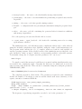
Where name is the name of the model, version is the version, and description allows
the description of the model. Models can also contain:
• other models (enabled or disabled)
• environment
–
–
–
–
constant variables
location of function files
time units
data types
• agent types
–
–
–
–
name
description
memory
functions
• message types
– name
– description
– variables
2
2.1
Model in Multiple Files
It is possible to define a model in multiple files. FLAME reads a model from multiple files
as if the model was defined in one file. This capability allows different parts of a model
to be enabled or disabled easily. For example if a model includes different versions of a
sub-model that can be exchanged, or a subsystem of a model can be disabled to see how it
affects the model. Alternatively this capability could be used as a hierarchy, for example
a ‘body’ model could include a model of the ‘cardiovascular system’ that includes a model
of the ‘heart’. The following tags show the inclusion of two models, one enabled and one
disabled:
<models>
<model><file>sub_model_1.xml</file><enabled>true</enabled></model>
<model><file>sub_model_2.xml</file><enabled>false</enabled></model>
</models>
The location of any sub model should be relative to the original model xmml file.
2.2
Environment
The environment of a model holds information that maybe required by a model but is not
part of an agent or a message. This includes:
• constant variables – for setting up different simulations easily
• location of function files – the path to the implementations of agent functions
• time units – for easily activating agent functions dependent on time periods
• data types – user defined data types used by agent memory or message variables
This notion of environment does not correspond to an environment that would be a part
of a model where agents would interact with the environment. Anything that can change
in a model must be represented by an agent, therefore if a model includes a changeable
environment that agents can interact with, this in itself must be represented by an agent.
2.2.1
Constant Variables
These are constant variables that can be set at the start of simulation runs initial starting
values and cannot be altered thereafter. They can be defined as follows:
<constants>
<variable>
<type>int</type>
<name>my_constant</name>
3
<description>value read in initial simulation settings</description>
</variable>
</constants>
Varible names cannot have spaces, instead please use lower case letters, numbers, underscores and hyphens. This also applies to agent memory names, message names, data
type names and function names.
2.2.2
Function Files
Function files hold the source code for the implementation of the agent functions. The
location is relative to the location of the model xmml file. They are included in the
compilation script (Makefile) of the produced model:
<functionFiles>
<file>function_source_code_1.c</file>
<file>function_source_code_2.c</file>
</functionFiles>
2.2.3
Time Units
Time units are used to define time periods that agent functions act within. For example
a model that uses a calendar based time system could take a day to be the smallest time
step, i.e. one iteration. Other time units can then use this definition to define other time
units, for example weeks, months, and years.
A time unit contains:
• name – name of the time unit.
• unit – can contain ‘iteration’ or other defined time units.
• period – the length of the time unit using the above units.
An example of a calendar based time unit set up can be defined as:
<timeUnits>
<timeUnit>
<name>daily</name>
<unit>iteration</unit>
<period>1</period>
</timeUnit>
<timeUnit>
<name>weekly</name>
4
<unit>daily</unit>
<period>5</period>
</timeUnit>
<timeUnit>
<name>monthly</name>
<unit>weekly</unit>
<period>4</period>
</timeUnit>
<timeUnit>
<name>quarterly</name>
<unit>monthly</unit>
<period>3</period>
</timeUnit>
<timeUnit>
<name>yearly</name>
<unit>monthly</unit>
<period>12</period>
</timeUnit>
</timeUnits>
5
2.2.4
Data Types
Data types are user defined data types that can be used in a model. They are a structure
for holding variables. Single variables can be:
• C fundamental data types – int, float, double, char.
• static array – of size ten: variable_name[10].
• dynamic array – available by placing ‘_array’ after the data type name: variable_name_array (please do not use if possible as useage affects load balancing
on high performance computers).
For example:
<variables>
<variable>
<type>int</type>
<name>int_single</name>
<description>A single integer</description>
</variable>
<variable>
<type>int</type>
<name>int_list[2]</name>
<description>A list of 2 integers</description>
</variable>
<variable>
<type>int_array</type>
<name>int_dynamic_list</name>
<description>A list of integers that can change size</description>
</variable>
</variables>
Data types can hold the above types of variables and also other defined data types. In
the example below the data type line contains a variable of data type position which is
defined above it:
<dataTypes>
<dataType>
<name>position</name>
<description>position in 3D using doubles</description>
<variables>
<variable><type>double</type><name>x</name>
<description>position on x-axis</description>
6
</variable>
<variable><type>double</type><name>y</name>
<description>position on y-axis</description>
</variable>
<variable><type>double</type><name>z</name>
<description>position on z-axis</description>
</variable>
</variables>
</dataType>
<dataType>
<name>line</name>
<description>a line defined by two points</description>
<variables>
<variable><type>position</type><name>start</name>
<description>start position of the line</description>
</variable>
<variable><type>position</type><name>end</name>
<description>end position of the line</description>
</variable>
</variables>
</dataType>
</dataTypes>
2.3
Agents
An agent type contains a name, a description, memory, and functions:
<agents>
<xagent>
<name>Agent_Name</name>
<description></description>
<memory>
...
</memory>
<functions>
...
</functions>
</xagent>
</agents>
7
2.3.1
Agent Memory
Agent memory defines variables, where variables are defined by their type, C data types
or user defined data types from the environment, a name, and a description:
<memory>
<variable>
<type>int</type>
<name>id</name>
<description>identity number</description>
</variable>
<variable>
<type>double</type>
<name>x</name>
<description>position in x-axis</description>
</variable>
</memory>
Note: Agent memory variable cannot be called ’name’ as this is used to define the agent
type in simulation input files.
2.3.2
Agent Functions
An agent function contains:
• name - the function name which must correspond to an implemented function name
and must be unique across the model
• description
• current state - the current state the agent has to be in.
• next state - the next state the agent will transition to.
• condition - a possible condition of the function transition.
• inputs - the possible input messages.
• outputs - the possible output messages.
And as tags:
<function>
<name>function_name</name>
<description>function description</description>
<currentState>current_state</currentState>
8
<nextState>next_state</nextState>
<condition>
...
</condition>
<inputs>
...
</inputs>
<outputs>
...
</outputs>
</function>
The current state and next state tags hold the names of states. This is the only place
where states are defined. State names must coordinate with other functions states to
produce a transitional graph from a single start state to end many possible end states.
A function can have a condition on its transition. This condition can include conditions
on the agent memory and also on any time units defined in the environment. At any state
with outgoing transitions with conditions it must be possible for a transition to happen, i.e.
it must be possible for every agent to transition from the start state to an end state. Each
possible transition must be mutually exclusive, i.e. the order that the function conditions
are tested is not defined. A function named ‘idle’ is available to be used for functions that
do not require an implementation.
Conditions (that are not just time unit based) take the form:
• lhs – left hand side of comparison
• op – the comparison operator
• rhs – the right hand side of the comparison
Or in tags:
<lhs></lhs><op></op><rhs></rhs>
Sides to compare (lhs or rhs) can be either a value, denoted by value tags, a formula,
currently also in value tags, or another comparison rule. Values and formula can include
agent variables which are preceded by ‘a’.
The comparison operator can be one of the following comparison functions:
• EQ – equal to
• NEQ – not equal to
• LEQ – less than or equal to
• GEQ – greater than or equal to
9
• LT – less then
• GT – greater than
• IN – an integer (in lhs) is a member of an array of integers (in rhs)
or can be one of the following logic operators as well:
• AND
• OR
The operator ‘NOT’ can be used by placing ‘not’ tags around a comparison rule. For
example the following tagged rule describes the condition being true when the ‘z’ variable
of the agent is greater than zero and less than ten:
<condition>
<lhs>
<lhs><value>a.z</value></lhs>
<op>GT</op>
<rhs><value>0.0</value></rhs>
</lhs>
<op>AND</op>
<rhs>
<not>
<lhs><value>a.z</value></lhs>
<op>LT</op>
<rhs><value>10.0</value></rhs>
</not>
</rhs>
</condition>
A condition can also depend on any time units described in the environment. For
example the following condition is true when the agent variable ‘day_of_month_to_act’
is equal to the number of iterations since of the start, the phase, of the ‘monthly’ period,
i.e. twenty iterations as defined in the time unit:
<condition>
<time>
<period>monthly</period>
<phase>a.day_of_month_to_act</phase>
</time>
</condition>
10
Time conditions can also be encased within a ‘not’ tag in indicate the reverse condition.
Functions can have input and output message types. For example the following example
the function takes message types ‘a’ and ‘b’ as inputs and outputs message type ‘c’:
<inputs>
<input><messageName>a</messageName></input>
<input><messageName>b</messageName></input>
</inputs>
<outputs>
<output><messageName>c</messageName></output>
</outputs>
Message filters can be applied to message inputs and allow the messages to be filtered.
Filters are defined similar to function conditions but include message variables which are
prefixed by an ‘m’. The following filter only allows messages where the agent variable ‘id’
is equal to the message variable ‘worker_id’:
<input>
<messageName>firing</messageName>
<filter>
<lhs><value>a.id</value></lhs>
<op>EQ</op>
<rhs><value>m.worker_id</value></rhs>
</filter>
<sort>
<key>wage</key>
<order>descend</order>
</sort>
</input>
The previous example also includes the use of a sort tag. The sort tag uses a key, a
message variable, to sort the list in ‘ascend’ing or ‘descend’ing order via the order tag.
Other input filters available are called ‘box2d’ and ‘box3d’. These filters only allow
messages that are within a Cartesian box around the current agent. The variables ‘x’ and
‘y’ must be used in agent and message memory for ‘2d’ and additionally ‘z’ for using ‘3d’.
The value given to this filter is the distance from the agent to the side of the box. For
example a value of ‘1’ gives a box of size ‘2’. The value can be a number or an agent
memory variable using the ‘a.’ notation. The limits of the box are inclusive which means
messages with position on the edge of the box pass the filter.
<input>
<messageName>2d_location</messageName>
<filter>
11
<box2d>1.0</box2d>
</filter>
</input>
<input>
<messageName>3d_location</messageName>
<filter>
<box3d>a.apothem</box3d>
</filter>
</input>
Using filters in the model description enables FLAME to make message communication
more efficient by pre-sorting messages and using other techniques.
Messages can also be randomised using the random tag:
<input>
<messageName>firing</messageName>
<random>true</random>
</input>
2.4
Messages
Messages defined in a model must have a type which is defined by a name and the variables
that are included in the message. Variables cannot include dynamic arrays. The following
example is a message called ‘signal’ that holds a position in 3D.
12
<messages>
<message>
<name>signal</name>
<description>Holds the position of the sending agent</description>
<variables>
<variable>
<type>double</type>
<name>x</name>
<description>The x-axis position</description>
</variable>
<variable>
<type>double</type>
<name>y</name>
<description>The y-axis position</description>
</variable>
<variable>
<type>double</type>
<name>z</name>
<description>The z-axis position</description>
</variable>
</variables>
</message>
</messages>
13
3
Model Implementation
The implementations of each agent’s functions are currently written in separate files written
in C, suffixed with ‘.c’. Each file must include two header files, one for the overall framework
and one for the particular agent that the functions are for. Functions for different agents
cannot be contained in the same file. Thus, at the top of each file two headers are required:
#include "header.h"
#include "<agentname>_agent_header.h"
Where ‘<agent_name>’ is replaced with the actual agent name. Agent functions can
then be written in the following style:
/*
* \fn: int function_name()
* \brief: A brief description of the function.
*/
int function_name()
{
/* Function code here */
return 0; /* Returning zero means the agent is not removed */
}
The first commented part (four lines) is good practice and can be used to auto-generate
source code documentation. The function name should coordinate with the agent function
name and the function should return an integer. The functions have no parameters. Returning zero means the agent is not removed from the simulation, and returning the number
one removes the agent immediately from the simulation. Agents of type ‘agentname’ are
added to a simulation by:
add_agentname_agent(var1, .. varN);
New agents are only added at the start of the next iteration. This is because new agents
start in their start state and are only picked up by the simulation engine when all other
agents are also in their start states.
3.1
Accessing Agent Memory Variables
After including the specific agent header, the variables in the agent memory can be accessed
by capitalising the variable name:
AGENT_VARIABLE
To access elements of a static array use square brackets and the index number:
14
MY_STATIC_ARRAY[index]
To access the elements and the size of dynamic array variables use ‘.size’ and ‘.array[index]’:
MY_DYNAMIC_ARRAY.size
MY_DYNAMIC_ARRAY.array[index]
To access variables of a model data type use ‘.variablename’:
MY_DATA_TYPE.variablename
3.1.1
Using Model Data Types
The following is an example of how to use a data type called vacancy:
/* To allocate a local data type */
vacancy vac;
/* And initialise */
init_vacancy(&vac);
/* Initialise a static array of the data type */
init_vacancy_static_array(&vac_static_array, array_size);
/* Free a data type */
free_vacancy(&vac);
/* Free a static array of a data type */
free_vacancy_static_array(&vac_static_array, array_size);
/* Copy a data type */
copy_vacancy(&vac_from, &vac_to);
/* Copy a static array of a data type */
copy_vacancy_static_array(&vac_static_array_from,
&vac_static_array_to, array_size);
If the data type is a variable from the agent memory, then the data type variable name
must be capitalised.
15
3.1.2
Using Dynamic Arrays
Dynamic array variables are created by adding ‘_array’ to the variable type. The following
is an example of how to use a dynamic array:
/* Allocate local dynamic array */
vacancy_array vacancy_list;
/* And initialise */
init_vacancy_array(&vacancy_list);
/* Reset a dynamic array */
reset_vacancy_array(&vacancy_list);
/* Free a dynamic array */
free_vacancy_array(&vacancy_list);
/* Add an element to the dynamic array */
add_vacancy(&vacancy_list, var1, .. varN);
/* Remove an element at index index */
remove_vacancy(&vacancy_list, index);
/* Copy the array */
copy_vacancy_array(&from_list, &to_list);
If the dynamic array is a variable from the agent memory, then the dynamic array
variable name must be capitalised.
3.2
Sending and receiving messages
Messages can be read using macros to loop through the incoming message list as per the
template below, where ‘messagename’ is replaced by the actual message name. Message
variables can be accessed using an arrow ‘->’:
START_MESSAGENAME_MESSAGE_LOOP
messagename_message->variablename
FINISH_MESSAGENAME_MESSAGE_LOOP
Messages are sent or added to the message list by:
add_messagename_message(var1, .. varN);
16
4
Model Execution
FLAME contains a parser program called ‘xparser’ that parses a model XMML definition
into simulation program source code that can be compiled together with the agent functions
implementation source code. The xparser includes template files which are used to generate
the simulation program source code.
The xparser takes as parameters the location of the model file and an option for serial or
parallel (MPI) version, serial being the default if the option is not specified. A production
mode can also be switched on which removes any debugging features in the simulation
program.
xparser (Version 0.16.2)
Usage: xparser [XMML file] [-s | -p] [-f]
-s
Serial mode
-p
Parallel mode
-f
Final production mode
4.1
Generated Files
The xparser then generates simulation source code files in the same directory as the model
file. These files include documentation of the model:
• stategraph.dot – a directed acyclic graph of the states, functions and messages of
agents in the model
• stategraph_colour.dot – as above but functions are coloured
• process_order_graph.dot – as above but the message syncronisation is shown
• latex.dot – a latex document describing the model
The simulation program source code files:
• Makefile – the compilation script used by the program ‘make’
• xml.c – the source code file that handles inputs and outputs of the simulation
• main.c – the source code file containing the main program loop
• header.h – a C header file for global variables and function declarations between
source code files
• memory.c – the source code file that handles the memory requirements of the simulation
• low_primes.h – holds data used for partitioning agents
17
• messageboards.c – the source code that handles message functionality
• partitioning.c – the source code that handles the partitioning of agents between nodes
in parallel
• timing.c – the source code that provides timing routines
• Doxyfile – a configuration file for generating documentation using the program ‘doxygen’
• rules.c – the source code file containing the generated rules for function conditions
and message input filters
For each agent type an associated header file is created:
• <agent_name>_agent_header.h – the header file containing macros for accessing
agent memory variables
The simulation source code files then require compilation, which can be easily achieved
using the included compilation script ‘Makefile’ using the ‘make’ build automation tool.
The program ‘make’ invokes the ‘gcc’ C compiler, which are both free and available on
various operating systems. If the parallel version of the simulation was specified the compiler invoked by ‘make’ is ‘mpicc’ which is a script usually available on parallel systems.
To manually change the C compiler used the parameter ‘CC’ can be set:
make CC=gcc
To compile a model the message board library is required and the installation directory
is needed by the compilation script. Currently the directory for ‘libmboard’ is set in the
same location of the model file. This can also be manually changed by using the parameter
‘LIBMBOARD_DIR’:
make LIBMBOARD_DIR=/location/of/libmboard
The compiled program is called ‘main’. The parameters required to run a simulation
include the number of iterations to run for and the initial start states (memory) of the
agents, currently a formatted XML file.
FLAME Application: test_model_simple_everthing
Debug mode enabled
Usage: ./main <number of iterations> [<states_directory>]/<init_state>
<partitions> [-f # | -f #+#]
-f Output frequency, 1st # is frequency, 2nd # is the offset if required
The frequency of producing output files can also be set by the parameter ‘-f’.
18
4.2
Start States Files
The format of the initial start states XML is given by the following example:
<states>
<itno>0</itno>
<environment>
<my_constant>6</my_constant>
</environment>
<agents>
<xagent>
<name>agent_name</name>
<var_name>0</var_name>
...
</xagent>
...
</agents>
</states>
The root tag is called ‘states’ and the ‘itno’ tag holds the iteration number that these
states refer to. If there are any environment constants these are placed within the ‘environment’ tags. Any agents that exist are defined within ‘xagent’ tags and require the name of
the agent within ‘name’ tags. Any agent memory variable (or environment constant) value
is defined within tags with the name of the variable. Arrays and data types are defined
within curly brackets with commas between each element.
When a simulation is running after every iteration, a states file is produced in the same
directory and in the same format as the start states file with the values of each agent’s
memory.
For advanced usage one can use the ‘import’ and ‘output’ tags.
Import tags are used to include other locations of start state data. You have to provide
the location (from where the current file is located), the format (currently only ‘xml’ is
avaliable) and the type (either ‘environment’ data or ‘agent’ data). Currently the import
tags work to only one depth, they cannot be nested. The following import tags read
in agent and environment data from the file at ‘0_depth_1.xml’ and agent data from
‘../test7/0_depth_1_agent.xml’:
19
<imports>
<import>
<location>0_depth_1.xml</location>
<format>xml</format>
<type>agent</type>
</import>
<import>
<location>../test7/0_depth_1_agent.xml</location>
<format>xml</format>
<type>agent</type>
</import>
<import>
<location>0_depth_1.xml</location>
<format>xml</format>
<type>environment</type>
</import>
</imports>
Output tags are used to better define what output one wants to save from a simulation. Outputs can have two types, either ‘snapshot’ (where the whole simulation state,
environment and agents, is output) or ‘agent’ where the agent name is specified and only
that agent type is output. The format of the output can be specified (although only xml
is provided currently) and the output location. Finally the timing can be specified. The
‘period’ defines the number of iterations between producing output, for example a period
of 10 means data is output every 10 iterations, so if we start with iteration number 0 the
data will be output in iterations 10, 20, 30. . . . A phase can also be applied to the output
timing. A phase of 2 when used with a period of 10 means data is output 2 iterations after
it usually would, for example it would now be 2, 12, 22, 32. . . . The following example
outputs a snapshot every 10 iterations and the agent ‘agent_type_a’ every 10 iterations
starting at the second iteration:
20
<outputs>
<output>
<type>snapshot</type>
<format>xml</format>
<location></location>
<time>
<period>10</period>
<phase>0</phase>
</time>
</output>
<output>
<type>agent</type>
<name>agent_type_a</name>
<format>xml</format>
<location></location>
<time>
<period>10</period>
<phase>2</phase>
</time>
</output>
</outputs>
21