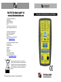
1
Test Products International Inc.
Headquarters
9615 SW Allen Blvd
Beaverton OR 97005
USA
503-520-9197 · Fax 503-520-1225
email: [email protected]
Test Products International Ltd.
342 Bronte St. South Unit #9
Milton, Ontario L9T 5B7
Canada
905-693-8558 · Fax 905-693-0888
email: [email protected]
Test Products International (Europe) Ltd
Longley House
International Drive
Southgate
Crawley
West Sussex
RH10 6AQ
Tel: +44 (0) 1293 530196
Fax: +44 (0) 1293 531870
e-mail: [email protected]
This symbol indicates that at the end of its life this
product must not be disposed of in household waste.
This equipment should be environmentally disposed
of. Please contact your supplier or manufacturer who
will be able to advise you on the correct method of
disposal.
TPI 85 User Manual © Version 1 (November 2005)
EC Declaration of Conformity
In accordance with BS EN ISO/IEC 17050-1
We, Test Products International Europe Ltd.
Of Longley House, International drive, Crawley, West Sussex RH10 6AQ
declare that:
Equipment:
Multi-Functional Earth – Loop Tester
Model Number: TPI 85
in accordance with the following Directives:
73/23/EEC
The Low Voltage Directorate
89/336/EEC
The Electromagnetic Compatibility Directive
Has been designed and manufactured to the following standards:
Appendix C: Guarantee
Your TPI 85 Multi Functional Earth Loop Tester is guaranteed free
from defects in materials and workmanship for 3 Years.
Covered by TPI:
Repair parts and labour; or replacement of the product at the option
of TPI. Normal transportation charges to the purchaser are also
covered.
Not covered by TPI:
Damage to the product which is the result of abuse, improper use or
maintenance is not covered. Any other expenses, consequential
damages, incidental expenses including damages to property are not
covered. Transportation expenses to the customer are not covered.
BS EN 61326
Electrical equipment for measurement, control
and laboratory use. EMC requirements.
BS EN 61010-1
Safety requirements for electrical equipment
for measurement, control and laboratory use.
General requirements.
To obtain warranty performance: - Include with the product your
name, address, phone number, written description of the problem
and proof of purchase date. Carefully package and return to TPI.
BS EN 61010-031
Safety requirements for electrical equipment
for measurement, control and laboratory use.
Safety requirements for hand held probe
assemblies for electrical measurement and
test.
Warning:
There are no user serviceable or replaceable parts within the
instrument. Removal of the cabinet cover will invalidate the warranty.
I hereby declare that the equipment named above has been designed
to comply with the relevant sections of the above referenced
standards. The unit complies with all the essential requirements of the
Directives.
This guarantee does not affect your statuary rights.
Signed by E. Quigley, Managing Director.
Test Products International Europe Ltd., at TPI Europe on 15th November 2005.
13
Appendix B Specification
Contents
Wiring Test
Detects missing E or N
Detects L-E or L-N swap
Polarity Test
Detects Live – Earth phase reversal by use of touchpad
Fault indicated by chart on front of instrument
Line Voltage Measurement
Range
LED
< 207V AC
207 – 253V AC
> 263V AC
Low (Red)
Standard (Green)
High (Red)
Loop Test
Result displayed on 6 LED’s
Test Current <15mA at 253V AC
Range
LED
Accuracy
<1W
< 10 W
< 100W
< 200 W
> 200
Green
Orange
Orange
Orange
Red
10% ±0.3W
Standards
CE Marked
BS EN 61010-1 300V CAT III
BS EN 61010-031
BS EN 61326 EMC
Important: This instrument is designed to operate safely on
domestic low voltage alternating current (AC)
systems only, which normally operate at around
230 V AC. It should not normally be subjected to
voltages above 300 V AC nor used on Direct
Current (DC) circuits.
1. Introduction
2. Why Measure Earth-Loop Impedance
3. Instrument Overview
3.1 Front View
3.2 Top View
3.3 Test Lead
4. Using the Multi – Function Earth Loop Tester
4.1 Correct Wiring Indicator
4.2 Voltage Indicator
4.3 Earth - Loop Test
4.4 Polarity Test
Appendix A: Fault Conditions Indication Chart
Appendix B: Specification
Appendix C: Guarantee
1. Introduction
Thank you for purchasing TPI brand products. The TPI 85 MultiFunction Earth Loop Tester is a state of the art, easy to use
instrument that is designed to test the safety of an electrical
appliance/installation. It can be used prior to or following any
adjustment, replacement of components, or fault finding
operations.
The instrument can be used to indicate in the order shown:
§
§
§
§
the correct or incorrect wiring of an electrical circuit
indicate the correct or incorrect voltage of the circuit
indicate the Earth - Loop Impedance of the circuit
indicate correct or incorrect polarity
The instrument is ruggedly constructed and comes with a 3 Year
Limited Guarantee (See Appendix C).
12
1
This manual will guide you through the functions of the TPI 85
which will give you many years of reliable service.
Your TPI 85 Multi-Function Earth Loop Tester comes complete
with:
l
l
l
l
One Test lead incorporating a UK style 3 pin plug (fitted with
a 13 Amp fuse) at one end and a IEC type connector fitted
at the other end, which interfaces with the instrument for
testing via Socket Outlets
A second test lead which is equipped with 3 separate probes
to enable testing via connections other than where a Socket
Outlet is present
Instruction Manual
Carry Case
2. Why Measure Earth Loop Impedance?
Whereas a digital multi-meter can be used to prove correct
wiring, voltage and polarity, the checking of Earth-Loop
Impedance can only be achieved using an instrument
specifically designed for this purpose.
The term ‘Impedance’ is defined as “the delay, or the preventing
of progress of something”. In the case of electricity, it is better
defined as “the opposition in a circuit to the flow of alternating
current, consisting of resistance and reactance”.
The TPI Multi-Function Tester is designed to indicate ‘Earth
Loop Impedance’, which can best be explained as a function
that can measure the resistance and reactance to the flow of an
alternating current in an electrical circuit.
Whereas measuring ‘Resistance to Earth’, using a digital multimeter will show that there is a good connection with low
resistance, between the two points being measured; it does not
prove how efficient the path to earth will be under fault
conditions.
2
5. Calibration & Servicing.
It is recommended that the unit is checked and calibrated as
annually. If required, TPI provide a service for the checking and
recalibration of instruments. Please consult Test Products
International for further details.
Appendix A: Fault Conditions Indication Chart
The chart below details the correct and fault conditions as
indicated by the various combinations of LED’s as shown by
the ‘Correct Wiring Indicator’ display
Display
Tone
●
Continuous
(3 seconds)
●●
Intermittent
Intermittent
Intermittent
Intermittent
Intermittent
Condition Indicated
Correct
L & E reversed, or L, N, E Incorrectly
connected
L & N reversed, or L, N, E Incorrectly
connected
Neutral Fault, or L & E Incorrectly
connected
Earth Fault, or L & N reversed
Live Fault, or N & E Incorrectly
Connected
No mains present
(confirm against known power source)
Ο
None
ΟΟ
Key:
● Continuous display of LED to indicate correct condition
= Flashing display of LED to indicate fault condition
Ο = Blank display to indicate no power to LED
= green flashing LED.
= Orange flashing LED.
=Red flashing LED
11
4.4 Polarity Test.
Upon completion of the Earth-Loop Impedance Test, a Polarity
Test should be conducted so as to confirm that the supply
system is correctly connected. Place a finger firmly on the
‘Touch Pad’ (See Figure 6) and maintain pressure for a few
seconds. The 3 LED’s of the ‘Correct Wiring Indicator’ will
remain green to indicate correct polarity. Incorrect Polarity is
indicated by the 3 LED’s intermittently flashing Red.
Checking the Earth-Loop Impedance will measure the
resistance of the earth path used by a current flow during a fault
condition. It will ensure that during any fault condition, the flow
of electricity to earth will be sufficient to cause the circuit
protective device e.g. fuse or circuit breaker, to rapidly halt the
flow of electricity through that circuit.
2. Instrument Overview
Wiring Indicator
Reference chart
Correct Wiring Indicator
Voltage Indicator
Figure 6.
Any failures should be investigated. This will normally be the
responsibility of the electricity supply company who should be
advised accordingly.
Earth - Loop Indicator
Polarity Test Pad
Earth-Loop Test Button
Figure 1.
10
3
3.1 Front View (see Figure 1)
Correct Wiring Indicator – Indicates the correct wiring of the
socket outlet under test by displaying three green Light emitting
Diodes (LED’s) and a continuous tone for 3 seconds.
Incorrect wiring is indicated by a series of orange or red flashing
LED’s and an intermittent tone being emitted.
Wiring Indictor Reference Chart – Helps identity the most
common fault conditions and how they are displayed by the
instrument.
Voltage indicator – Indicates the range of the voltage using the
ranges specified by British Standard BS7697:1993 (Nominal
voltages for low voltage public electricity supply systems).
Earth – Loop Indicator- On pressing the Earth – Loop Test
Button, an indication of the range of the earth – loop impedance
will be displayed.
Polarity Test Pad – On completion of all other tests, firmly
pressing the ‘Test Pad’ will confirm the polarity of the supply
system.
Earth – Loop Test Button – pressing this button starts the Earth
– Loop test.
WARNING:
The TPI 85 Multi-Function Earth Loop Tester is a mains powered
instrument and therefore does not incorporate an internal battery.
There are no user serviceable parts inside the instrument and
therefore the rear case of the instrument should not be removed.
Acceptable Earth-Loop Impedance results depend on the type of
circuit and the circuit protective device (fuse, Miniature Circuit
Breaker [MCB] or Residual Current Device [RCD]) employed to
protect the circuit under fault condition. Recommended Earth Loop
Impedance results are detailed in British Standard 7671 (IEE
Regulations) however, for guidance the indications displayed by
this unit are discussed below:
<1 W
Any Earth Loop Impedance values of less than 1 Ohm
can be considered acceptable and should be found in
about 90% of most domestic electrical installations.
<10 W This is still normally considered to be an acceptable
reading, but it may indicate a loose earth connection and
it may be worth checking the adequacy of the
connection at the point of test. If the point of test is at the
extreme of the electrical circuit, then earth – loop
impedance readings can be expected to be higher.
<100 W Such a reading should cause concern and should be
investigated. However, if the electrical supply system is
fed via overhead cables (known as a TT supply system)
and an earth is provided via a spike driven into the
ground, then the reading may normally be considered as
acceptable.
<200 W For any other supply system than a TT (as discussed
above) this must be considered as a serious earth fault
and should be investigated and corrected. Where a TT
supply system is employed, providing the circuit is also
protected by a Residual Current Device (RCD) rated at
either 30mA or 100 mA then the reading may normally
be considered as adequate.
>200 W Any results exceeding 200 Ohms need to be investigated
and resolved as a matter of urgency.
NOTE: In the event of a concern about an electrical installation
please consult a qualified electrician.
4
9
Note: This test is only performed after the instrument has first
proved that the wiring is connected correctly (i.e. All
correct wiring indicators are continuously green.
While the voltage is being checked, the two outer red LED’s of
the voltage indicator will be briefly illuminated. On completion of
the check, the actual voltage range will be indicated by the
appropriate LED as shown in Figure 4 below. The supply
voltage can be considered correct if the centre green LED is lit,
indicating a voltage between 207 & 253 V AC. Other voltage
range indications should be investigated accordingly.
3.2 Top View
Figure 2.
The top of the instrument (see Figure 2) incorporates an IEC
type connector that is used to connect the test leads (supplied)
to the unit.
3.3 Test Leads.
Figure 4.
4.3 Earth - Loop Test.
After confirming correct voltage, press and release the Earth
Loop Test Switch Button. The outer two (<1 W & >200 W) LED’s
of the Earth Loop Indicator (See Figure 5) will illuminate briefly
while the test is being undertaken. On completion of the test, the
LED indicating the measured Earth-Loop Impedance will remain
illuminated.
Figure 3a Test Lead with 13 Amp Plug
Figure 3b Test Lead with 3 separate probes
Two test leads are supplied with the instrument (see Figure
3a & 3b). Both incorporate an IEC connector at one end,
which connects to the socket on the top of the instrument.
One test lead has a UK style 3 pin plug at the other end,
which can be
Figure 5.
8
5
used to perform testing via socket outlets of the electrical circuit
to be tested. The other test lead incorporates 3 separate test
probes at the other end of the lead, which enables testing from all
other locations other than where a Socket Outlet is available e.g.
at the point of connection to separate components such as
pumps or fans etc.
Before use, the instrument case, its test leads and probes should
be checked for signs of damage or wear and if any damage is
identified should not be used until repaired or replaced. The plug
is fitted with a 13 Amp fuse and should be checked and replaced
as necessary if the unit fails to operate while connected to a
known powered circuit.
continuously on a continuous tone will be emitted for 3 seconds.
If there is a wrong connection or a wire not connected, the LED’s
will be flashing and an intermittent bleep will be heard whilst the
instrument remains connected to the power supply.
Fault conditions, showing the colours of the flashing LED’s for
most normal fault conditions are shown in the chart on the front of
the instrument, immediately above the ‘Correct Wiring Indicator’
as shown in Figure 3. Full details of all fault conditions as shown
in the Fault Conditions Indication Chart - Appendix 1
3. Using the Multi-function Earth - Loop Tester
Warning.
The TPI Multi-Function Tester is a mains powered instrument and
does not rely on an internal battery. There are no user
serviceable or replaceable parts within the instrument. Removal
of the cabinet cover will invalidate the warranty.
The Multi-Function tester automatically self checks and starts its
series of tests as soon as it is connected to a ‘live’ power supply.
The tests are conducted in the following order.
4.1 Correct Wiring Test
Connect the instrument to the circuit to be tested and energise
the circuit. The instrument will automatically ‘self test’ and
check the Earth, Live and Neutral connections at the point of
connection. During the tests a series of short bleeps will be
heard and the Light Emitting Diodes (LED’s) will flash.
Providing no problems are identified with the circuit under test,
the three green LED’s of the correct wiring indicator will remain
6
Figure 3.
4.2 Voltage Indicator.
After checking and confirming correct wiring, the instrument will
automatically check the supply voltage.
7