1
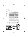
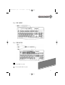
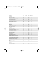
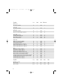
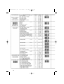
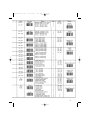
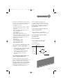
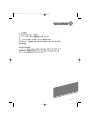
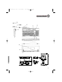
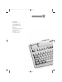
644-0130.03 e,ch
17.07.2001
7:35 Uhr
Seite 43
User Manual
Advanced Performance Line
Printed on recycled paper.
644-0130.03 e,ch
17.07.2001
7:35 Uhr
Seite 2
Table of Contents –
English
Page
Plug Ins _______________________________________________________________________ III
Key to diagram __________________________________________________________________ 2
Application of this manual ________________________________________________________ 3
Examples of layouts ____________________________________________________________4-6
1.
General Advice _____________________________________________________________ 7
2.
Introduction ________________________________________________________________ 7
2.1 General Description _________________________________________________________ 7
2.2 Description of the magnetic stripe card reader _________________________________ 7
2.3 Description of the barcode reader _____________________________________________ 8
2.4 Description of the smart card reader __________________________________________ 8
2.5 G 80-8212: keylock switch ___________________________________________________ 8
2.6 Model 8100 series; touchpad ________________________________________________ 8
2.7 G 81-8308 _________________________________________________________________ 8
2.8 Model Core Plus ____________________________________________________________ 8
3.
Installation _________________________________________________________________ 8
3.1 System requirements _______________________________________________________ 8
3.2 Software __________________________________________________________________ 9
4.
Programming _______________________________________________________________ 9
4.1 Definition of terms header and terminator _____________________________________ 9
4.2 Programming the magnetic card reader and barcode unit ________________________ 9
4.3 Programming the free programmable keys ____________________________________ 10
4.4 Programming examples ____________________________________________________ 22
4.5 Example for programming a free programmable key ___________________________ 23
4.6 G 81-8308: keyboard with 24 free programmable keys _________________________ 24
5.
Using the magnetic stripe card reader ________________________________________ 26
5.1 Cleaning the magnetic head ________________________________________________ 26
6.
Connecting of barcode reading devices (Versions with barcode option only) _______ 26
7.
Using the integrated smart card teminals _____________________________________ 27
7.1 Inserting the smartcard _____________________________________________________ 27
7.2 Inserting plug in cards ______________________________________________________ 28
8.
Firmware _________________________________________________________________ 28
9.
Status indicators ___________________________________________________________ 28
10. Technical specifications _____________________________________________________ 28
10.1 Technical specifications for the keyboard _____________________________________ 28
10.2 Technical specifications magnetic swipe card reader ___________________________ 29
10.3 Technical specifications for the barcode decoder unit __________________________ 29
10.4 Technical specifications for the smart card terminal ____________________________ 29
10.5 Technical specifications for touchpad _________________________________________ 29
11. Troubleshooting ___________________________________________________________ 30
12. Optional accessoires _______________________________________________________ 31
Chinese _______________________________________________________________________ 32
II
644-0130.03 e,ch
17.07.2001
7:35 Uhr
Seite 3
3
4
LOCK
LOCK
LOCK
III
1
2
644-0130.03 e,ch
17.07.2001
7:35 Uhr
Seite 2
Key to diagram
➭ Figure page IV
➭ Figure page III
Keyboard 7000 series
Front of keyboard
Keyboard 8000 series
Front of keyboard
➀ Vertical smart card slot (G 81-8900)
➁ Horizontal smart card slot (G 81-8901)
➂ Barcode connector, 6pol
right (Barcode 2)
➃ LEDs indicating status of keyboard
and function
➄ Keyboard cable and plug
Rear side of keyboard 8000 series
⑥ Barcode connector, 9pol
right (Barcode !)
⑦ RS 232 connector
Bottomside of keyboard 8000 series
➇ Cable channel
➈ Plug in housing cover
➉ Adjustable feet
11 Smart card terminal interface (RS 232)
9- pin SUB-D plug
12 Keyboard plug DIN or mini DIN
➭ Fold out front and back page of
manual
Keyboard 8000 series and 7000 series
Plug ins
➊
➋
➌
➍
2
Plug in housing
Locking device
Bevelled edges
Guide channel
➀ Vertical smart card slot
➁ LEDs indicating status of keyboard and
function
➂ Keyboard cable and plug
Rear side of keyboard 7000 series
➃ Barcode connector, 9pol
right (Barcode 1)
➄ RS 232 connector
➅ Barcode connector, 6pol
right (Barcode 2)
Bottomside of keyboard 7000 series
➆ Cable channel
➇ Plug in housing cover
➈ Adjustable feet
➉ Smart card terminal interface (RS 232)
9- pin SUB-D plug
Keyboard plug DIN or mini DIN
644-0130.03 e,ch
17.07.2001
7:35 Uhr
Seite 3
Developed above all with professional
typing applications in mind, Cherry
keyboards fulfill all important
requirements posed by the market and
ergonomics. They embody mature innovative and user-friendly technology that is
optimally suited for successful office and
dataprocessing.
Applications of this
manual
This manual is applicable to keyboards of
series 7000 and 8000, G 80 as well as
G 81-8308. The keyboard layouts shown
depict the positioning of the freely
programmable function keys as well as
the integrated card reading devices,
which differ according to the various
moolets.
Examples of layouts:
3
644-0130.03 e,ch
17.07.2001
7:35 Uhr
Ex. G 81-7002
Ex. G 80-7009
relegendable keycaps
free programmable keycaps
4
Seite 4
644-0130.03 e,ch
17.07.2001
7:35 Uhr
Seite 5
Ex. G 81-8002
Ex. G 80-8109
relegendable keycaps
free programmable keycaps
5
644-0130.03 e,ch
17.07.2001
7:35 Uhr
Ex. G 80-8202
Ex. G 81-8308
relegendable keycaps
free programmable keycaps
6
Seite 6
644-0130.03 e,ch
17.07.2001
7:35 Uhr
Seite 7
1.General Advice
2. Introduction
Cherry continually optimizes its products
in accordance with technological
developments. We therefore reserve the
right to make any technical alterations.
The establishment of reliability as well as
the definition of technical details takes
place according to Cherry’s internal
examinations, which comply with
generally recognized regulations or
standards. Requirements which deviate
from these norms are to be covered
through the determined operating
conditions by the user. lf necessary, we
are also available to help. Improper
handling, storage, external influences
and/or further processing can lead to
disturbances and defects during use. We
stress that we do not grant any warranty
or accept any liability if our product is
altered by the user, the exception being
that this is released expressly in writing
for the specific case of use. This is also
especially valid if repairs and maintenance
work have not been carried out by
trained personnel. To avoid danger of
explosion, the optional lithium battery
may only be exchanged by an expert.
Possible compensation claims against us
whatever the legal are out of the
question as long as they do not concern
intent or negligence on our behalf. The
abovementioned restriction does not
apply to compensation claims, according
to the Product Liability Law. The
following operating instructions are only
valid for the accompanying product.
2.1 General Description
The Cherry G 81-8000 (standard format)
and G 81-7000 (19” compact format) as
8100, CorePlus and 8300 are a new
generation of chip card reader keyboards.
With this keyboard chip cards, magnetic
cards and barcode readers, plug ins and
touchpad can be handled within one
application.
2.2 Description of the magnetic
stripe card reader
The integrated swipe-type magnetic
stripe card reader is capable of reading
all magnetic stripe card types described
in DIN ISO 7812. The versions with a 3track magnetic card allow the possibility
to read the max. 3 tracks separately, in
pairs or all together. The selection of the
tracks can be chosen by the user. The 2track versions offer the possibility to read
the tracks separately or simultaneously.
The magnetic card data is converted to
the conresponding keyboard scan codes
and then transmitted via the keyboard
interface to the computer.
Please look in the Internet
(http://www.cherry.de) for the
most up-to-date information.
7
644-0130.03 e,ch
17.07.2001
7:35 Uhr
2.3 Description of the barcode
reader
The keyboards with barcode option are
equipped with an integrated barcode
decoder. With this barcode decoder and
a reading device, it is possible to decode
the following barcode types: Code 39,
Code 93, Code 11, Code 16K, Plessey,
MSI, Industrial 2/5, Matrix 2/5,
Interleaved 2/5, Codabar, Code 128,
UPC/EAN/JAN. Detection of the various
barcode types is automatic. The barcode
reader data is converted to the
corresponding keyboard scan codes and
then transmitted to the computer via the
keyboard interface.
2.4 Description of the smart card
reader
The integrated smart card reader is
capable of reading and writing smart
cards of DIN ISO/IEC 7816.
2.5 G 80-8212: keylock switch
Depending on the position of the keylock
switch, the following codes are returned:
Lock position (L):
E0 16 E0 F0 16
Operator position (O): E0 1E E0 F0 1E
Manager position (M): E0 26 E0 F0 26
Aux 1 position (1):
E0 25 E0 F0 25
Aux 2 position (2):
E0 00 E0 F0 00
2.6 Model 8100 series: touchpad
This family of keyboards also includes a
touchpad, intended as a substitute for a
mouse. The touchpad is compatible with
PS/2 and serial (RS 232) ports. An
adapter is required in order to connect
the keyboard to an RS 232 interface
(cf. Accessories)
8
Seite 8
2.7 G 81-8308
Keyboard with 24 programmable keys,
each with ten programmable levels
(cf. also section 4.6)
2.8 Model Core Plus
Keyboard with integrated smartcard
terminal based on GEMCORE from
Gemplus. The keyboard can incorporate
any or all of the following components: 2
main cards, 4 SIMM modules, 4 Mbit
flash RAM for data, 128 Kbit RAM, real
time clock, battery-backed buffer for RTC
and RAM, RS 232 interface. Power is
supplied through the keyboard port.
You can obtain the required driver
software from Gemplus under
http://www.gemplus.com
3. Installation
3.1 System requirements
The keyboard has been developed for
operation together with an IBM, AT, PS/2
or 100% compatible computer.
Warning!
Smartcards contain data that may have
considerable (financial) value, as well as
personal secret (cryptographic) keycodes:
➭ Take precautions against theft and
misuse!
To install the keyboard, proceed as
follows:
➭ Switch your computer off
➭ Unplug the old keyboard
(for versions with touchpad also the
644-0130.03 e,ch
17.07.2001
7:35 Uhr
mouse)
➭ Plug in the Cherry keyboard
➭ For versions with Smart card reader:
connect 9-pin SUB-D plug to the
RS 232 port (for versions with
touchpad the 6-pin Mini-Din plug)
➭ Switch your computer back on
After being powered up, the computer
and the keyboard perform a self-test.
Once the self-test has been successfully
completed and the operating system has
been loaded, you can begin working with
the new keyboard. Please check to make
sure that the keyboard works properly. lf
an error message is displayed or
meaningless characters are displayed on
screen after the computer is switched
on, please check to make sure that the
keyboard is properly connected to the
computer.
3.2. Software
The keyboard comes complete with
configuration software. This utility allows
you to store and manage various
keyboard configurations, and also to
configure any supplementary keyboard
features (e.g. barcode readers, magnetic
card scanners, programmable function
keys (PF) and so on) to suit your
individual preferences or requirements.
The G81-8308 keyboard family also
comes with Cherry’s TAP utility. This
program shows you the current configuration and layout of the ten
storage layers available for each
programmable key on the keyboard.
Software updates and version upgrades
can be obtained from Cherry’s Internet
website at http://www.cherry.de.
Seite 9
Note
Launching the configuration software
automatically disables the manual
keyboard programming function.
4. Programming
4.1 Definition of terms header
and terminator
Header: The header indicates the start of
a containing data from the magnetic card
reader or the barcode reader. The header
code is a code sequence being
transmitted first over the keyboard
interface prior to sending the actual
magnetic card reader or barcode reader
data.
Terminator: The terminator indicates the
end of a transmission containing data
from the magnetic card reader or the
barcode reader. The terminator code is a
code sequence being transmitted over
the keyboard interface after sending the
actual magnetic card reader or barcode
reader data.
4.2 Programming the magnetic
card reader and barcode unit
If you want to enter the programming
menu scan the “Enter Prog Mode” label
or press the 6 mode keys (SHIFT left,
9
644-0130.03 e,ch
17.07.2001
7:35 Uhr
SHIFT right, CTRL left, CTRL right, ALT
left, ALT right) at the same time for at
least 3 seconds. The keyboard will
perform two beeps to indicate that the
programming menu has been entered or
left. When you entered the menu a short
beep will indicate a valid input and a long
beep will indicate a wrong input. If you
want to exit the programming menu scan
the “Exit Prog Mode” label or press the
space bar. It is helpful to run an editor
program on your PC while programming
the keyboard to get all status messages
onto the screen.
4.3 Programming the
free programmable keys
(without G 81-8308)
If you want to enter the programming
menu for the free programmable keys
scan the “Enter Prog Mode” label or
press the 6 mode keys (SHIFT left,
SHIFT right, CTRL left, CTRL right, ALT
left, ALT right) at the same time for at
least 3 seconds. The keyboard will
perform two beeps to indicate that the
programming menu has been entered.
Select the free programmable key you
like to program by pressing. Type the
keystring you like to program. It is
possible to program all keys or key
combinations up to a stringlength of 16
characters. To finish the string press the
key you like to programm for a second
time. If you want to exit the
programming menu scan the "Exit Prog
Mode" label or press the space bar.
10
Seite 10
The following list shows the options of
the programming menu.
Refer chapter 4.4 for some examples.
644-0130.03 e,ch
17.07.2001
7:35 Uhr
Seite 11
11
644-0130.03 e,ch
17.07.2001
7:35 Uhr
Option
Seite 12
1st
2nd
Code 39
Decoding enabled
Start/Stop Charakter included
Check Digit required
Check Digit included
Full ASCII selected
Adaptive Algorithm selected
Append Option selected
A
A
A
A
A
A
A
1
2
3
4
5
6
7
Y/N
Y/N
Y/N
Y/N
Y/N
Y/N
Y/N
Y
N
N
N
N
N
N
Code 128
Mode A
Mode B
Mode C
Leading FNC1 required
FNC Digit included
C
C
C
C
C
1
2
3
4
5
Y/N
Y/N
Y/N
Y/N
Y/N
Y
Y
Y
N
N
Codabar
Decoding enabled
Start & Stop Character included
Concatenation enabled
Concatenation required
F
F
F
F
1
2
3
4
Y/N
Y/N
Y/N
Y/N
Y
N
Y
N
I
I
I
I
1
2
3
4
Y/N
Y/N
Y/N
Y/N
Y
N
N
N
Industrial 2/5
Streight 2/5 Decoding enabled
IATA 2/5 Decoding enabled
IATA 2/5 Mod7 Check Digit required
S
S
S
1
2
3
Y/N
Y/N
Y/N
Y
Y
N
MSI
Decoding enabled
M
1
Y/N
Y
Plessey
Decoding enabled
P
1
Y/N
Y
Interleaved 2/5
Decoding enabled
Check Digit
required
Check Digit included
Adaptive Algorithm Selected
12
3rd Default
644-0130.03 e,ch
17.07.2001
7:35 Uhr
Seite 13
Comment
Start/Stop character in output string transmitted
Only label with check digit accepted
Check digit transmitted if available
Extendend Code 39 option selected
Aggressive algorithm which accepts dirty or bad labels (greater tolerance).
Chaining of Code 39 labels possible.
Special character set selected
Special character set selected
Special character set selected
Only label with leading FNC 1 accepted
FNCx character transmitted if available
Start/Stop character in output string transmitted
Chaining of labels possible
Chaining of labels required
Only label with check digit accepted
Check digit transmitted if available
Aggressive algorithm which accepts dirty or bad labels (greater tolerance)
Only label with check digit accepted
13
644-0130.03 e,ch
17.07.2001
7:35 Uhr
Seite 14
Option
1st
2nd
Matrix 2/5
Decoding enabled
X
1
Y/N
Y
Code 93
Decoding enabled
G
1
Y/N
Y
Code 11
Decoding enabled
Only one Check Digit required
H
H
1
2
Y/N
Y/N
Y
N
Code 16K
Decoding enabled
Leading FNC1 required
FNC Digit included
Click on each row
K
K
K
K
1
2
3
4
Y/N
Y/N
Y/N
Y/N
Y
N
N
N
EAN/JAN
EAN 13 Decoding enabled
EAN 8 Decoding enabled
Check Digit included
UPC/EAN Addendum required
EAN 2-Digit Addendum enabled
EAN 5-Digit Addendum enabled
E
E
E
E
E
E
1
2
3
4
5
6
Y/N
Y/N
Y/N
Y/N
Y/N
Y/N
Y
Y
Y
N
Y
Y
UPC
UPC-A Decoding enabled
UPC-E0 Decoding enabled
UPC-E1 Decoding enabled
UPC-E Data Expand to A-Format
Exp. Format: System Digit included
Exp. Format. Check Digit included
Compressed Format: System Digit included
Compressed Format: Check Digit included
2-Digit Addendum enabled
5-Digit Addendum enabled
U
U
U
U
U
U
U
U
U
U
1
2
3
4
5
6
7
8
9
0
Y/N
Y/N
Y/N
Y/N
Y/N
Y/N
Y/N
Y/N
Y/N
Y/N
Y
Y
Y
N
Y
Y
Y
Y
Y
Y
Option
1st
2nd
3rd
4th
5th
Min/Max length
Min Length
Max Length
A-U
A-U
O
B
0-9
0-9
0-9
0-9
0-9
0-9
14
3rd Default
644-0130.03 e,ch
17.07.2001
7:35 Uhr
Seite 15
Comment
Only label with one check digit accepted
Only label with leading FNC1 accepted
FNCx character transmitted if available
Click on every successfully read row
Output with check digit
Only labels with supplemental accepted
2 digit supplemental enabled
5 digit supplemental enabled
12 digit UPC-A Code enabled
Output with zero suppression
Output with non zero suppression
8 digit label expand to 12 digit output
Expanded Format with system digit
Expanded Format with check digit
Compressed Format (8 digit) with system digit
Compressed Format (8 digit) with check digit
2 digit supplemental enabled
5 digit supplemental enabled
Comment
15
644-0130.03 e,ch
17.07.2001
7:35 Uhr
Option
Seite 16
1st
2nd
Barcode/ Header & Terminator
Barcode 1 Header Enable/Disable
Barcode 2 Header Enable/Disable
Define and Enable Barcode 1 Header
Q
Q
Q
1
2
3
Y/N
Y/N
–
N
N
not def.
Define and Enable Barcode 2 Header
Q
4
–
not def.
Barcode 1 Terminator Enable/Disable
Barcode 2 Terminator Enable/Disable
Define and Enable Barcode 1 Terminator
T
T
T
1
2
3
Y/N
Y/N
–
N
N
not def.
Define and Enable Barcode 2 Terminator
T
4
–
nor def.
Magnetic card/ Header & Terminator
Track 1 header Enable/Disable
Track 2 header Enable/Disable
Track 3 header Enable/Disable
Track 4 header Enable/Disable
Define and Enable Track 1 Header
V
V
V
V
V
1
2
3
4
5
Y/N
Y/N
Y/N
Y/N
–
N
N
N
N
not def.
Define and Enable Track 2 Header
V
6
–
not def.
Define and Enable Track 3 Header
V
7
–
not def.
Define and Enable Track 4 Header
V
8
–
not def.
Track 1 Terminator Enable/Disable
Track 2 Terminator Enable/Disable
Track 3 Terminator Enable/Disable
Track 4 Terminator Enable/Disable
Define and Enable Track 1 Terminator
W
W
W
W
W
1
2
3
4
5
Y/N
Y/N
Y/N
Y/N
–
N
N
N
N
not def.
Define and Enable Track 2 Terminator
W
6
–
not def.
Define and Enable Track 3 Terminator
W
7
–
not def.
Define and Enable Track 4 Terminator
W
8
–
not def.
16
3rd Default
644-0130.03 e,ch
17.07.2001
7:35 Uhr
Seite 17
Comment
After 1st label and 2nd label you can enter the header/terminator string. End of string:
Enter key (NUM Pad).
After 1st label and 2nd label you can enter the header/terminator string. End of string:
Enter key (NUM Pad).
After 1st label and 2nd label you can enter the header/terminator string. End of string:
Enter key (NUM Pad).
After 1st label and 2nd label you can enter the header/terminator string. End of string:
Enter key (NUM Pad).
After 1st key and 2nd
Enter key (NUM Pad)
After 1st key and 2nd
Enter key (NUM Pad)
After 1st key and 2nd
Enter key (NUM Pad)
After 1st key and 2nd
Enter key (NUM Pad)
key you can enter the header/terminator string. End of string:
key you can enter the header/terminator string. End of string:
key you can enter the header/terminator string. End of string:
key you can enter the header/terminator string. End of string:
After 1st key and 2nd key you can enter
Enter key (NUM Pad)
After 1st key and 2nd key you can enter
header/terminator string. End of string:
Enter key (NUM Pad)
After 1st key and 2nd key you can enter
header/terminator string. End of string:
Enter key (NUM Pad)
After 1st key and 2nd key you can enter
header/terminator string. End of string:
Enter key (NUM Pad)
the header/terminator string. End of string:
the
the
the
17
644-0130.03 e,ch
17.07.2001
7:35 Uhr
Option
Seite 18
1st
2nd
Barcode Options
Code ID (WA)
Code ID (AIM)
Modifier (AIM)
Laser voting
Beep on good read
Set Code Options to default
Disable Code Options
R
R
R
R
R
R
R
1
2
3
4
5
6
7
Y/N
Y/N
Y/N
Y/N
Y/N
–
–
N
N
N
Y
Y
–
–
Magnetic Card Options
Track 1 reading Enable/Disable
Track 2 reading Enable/Disable
Track 3 reading Enable/Disable
Track 4 reading Enable/Disable
Stop character check
LRC character check
Send immediate
J
J
J
J
J
J
J
1
2
3
4
5
6
7
Y/N
Y/N
Y/N
Y/N
Y/N
Y/N
Y/N
Y
Y
Y
N
Y
Y
Y
Keyboard Options
Define Delay Time
Z
1
0-9
6
Downcode only Enable/Disable
Keyclick Enable/Disable
Online Programming Enable/Disable
Configuration output
Z
Z
Z
Z
2
3
4
5
Y/N
Y/N
Y/N
–
N
N
Y
–
18
3rd Default
644-0130.03 e,ch
17.07.2001
7:35 Uhr
Seite 19
Comment
Code ID Welch Allyn transmitted, see PROG-MENU
Code ID AIM transmitted, see PROG-MENU
AIM Modifier transmitted, see PROG-MENU
Keyboard will compare 3 consecutive laser scans before output
Only Barcode options affected
Only Barcode options affected
Stop character test while reading magnetic card reader
LRC test while reading magnetic card data
Immediate output of magnetic card data
Delay time for barcode and magnetic-card output in milliseconds
(time in beetween the codes)
If enabled no upcode is sent at barcode and magnetic-card output
If enabled the selected options in the menuing mode will be sent to the system
19
644-0130.03 e,ch
20
17.07.2001
7:35 Uhr
Seite 20
644-0130.03 e,ch
17.07.2001
7:35 Uhr
Seite 21
21
644-0130.03 e,ch
17.07.2001
7:35 Uhr
4.4 Programming examples
Examples for barcode
programming
Example 1:
Setting barcode options to default.
For setting the barcode options to default
status proceed as follows:
1. Press the six mode keys (SHIFT left,
SHIFT right, CTRL left, CTRL right, ALT
left, ALT right) for at least 3 seconds to
enter the programming mode
(Keyboard beep, menu entry on
screen).
2. Press the “R”-key.
3. Press the “6”-key
4. Press the Space-key to exit the
programming mode.
Example 2:
Enable/Disable Code 39 decoding
(via keyboard). To enable/disable the
barcode CODE 39 proceed as follows:
1. Press the six mode keys (SHIFT left,
SHIFT right, CTRL left, CTRL right, ALT
left, ALT right) for at least 3 seconds to
enter the programming mode
(Keyboard beep, menu entry on
screen).
2. Press the “A”-key.
3. Press the “1”-key.
4. Press the “Y”-key to enable the
decoding of Code 39. If you would like
to disable the decoding press the “N”key.
5. Press the Space-key to exit the
programming mode.
Example 3:
Define and Enable barcode header 1. To
define and enable a barcode header
proceed as follows:
1. Press the six mode keys (SHIFT left,
22
Seite 22
SHIFT right, CTRL left, CTRL right, ALT
left, ALT right) for at least 3 seconds to
enter the programming mode
(Keyboard beep, menu entry on
screen).
2. Press the “Q”-key.
3. Press the “3”-key.
4. Type in the keystring you like to
program (e.g. “BH1”). To finish the
string press the Enter-key at the
numeric key pad.
5. Press the Space-key to exit the
programming mode.
Example 4:
Define and Enable barcode terminator 1.
To define and enable a barcode
terminator proceed as follows:
1. Press the 6 mode keys (SHIFT left,
SHIFT right, CTRL left, CTRL right, ALT
left, ALT right) for at least 3 seconds to
enter the programming mode
(Keyboard beep, menu entry on
screen).
2. Press the “T”-key.
3. Press the “3”-key.
4. Type in the keystring you like to
program. To finish the string press the
Enter key at the numeric key pad.
5. Press the Space-key to exit the
programming mode.
Examples for magnetic card
reader programming
Example 1:
Enable/Disable magnetic card reader
track 1 decoding.
To enable/disable the magnetic card
reader proceed as follows:
1. Press the six mode keys (SHIFT left,
SHIFT right, CTRL left, CTRL right, ALT
left, ALT right) for at least 3 seconds to
enter the programming mode
644-0130.03 e,ch
17.07.2001
7:35 Uhr
(Keyboard beep, menu entry on
screen).
2. Press the “J”-key.
3. Press the “1”-key.
4. Press the “Y”-key to enable the
magnetic card reader. If you would like
to disable the magnetic card reader
press the “N”-key.
5. Press the Space-key to exit the
programming mode.
Example 2:
Define and Enable magnetic card reader
track 1 header. To define and enable the
header for the magnetic card track 1
proceed as follows:
1. Press the six mode keys (SHIFT left,
SHIFT right, CTRL left, CTRL right, ALT
left, ALT right) for at least 3 seconds to
enter the programming mode
(Keyboard beep, menu entry on
screen).
2. Press the “V”-key.
3. Press the “5”-key.
4. Type in the keystring you like to
program (e.g. “MH1”). To finish the
string press the Enter key at the
numeric key pad.
5. Press the space-key to exit the
programming mode.
Seite 23
4. Type in the keystring you like to
program. To finish the string press the
selected free programmable key again.
5. Press the Space-key to exit the
programming mode.
4.5 Example for programming a
free programmable key
(without G 81-8308)
To program a string on the "Break" key
(key-no. 126) proceed as follows:
1. Press the six mode keys (SHIFT left,
SHIFT right, CRTL right, ALT left, ALT
right) for at least 3 seconds to enter
the programming mode (keyboard
beep, menu entry on screen).
2. Press the "Break" key.
3. Type the keystring you like to program
(maximal 16 characters). To finish the
string press the ”Break“ key at the
numeric key pad.
4. Press the Space-key to exit the
programming mode.
Example 3: Define and Enable magnetic
card reader track 1 terminator. To define
and enable the terminator for the
magnetic card reader track 1 proceed as
follows:
1. Press the six mode keys (SHIFT left,
SHIFT right, CTRL left, CTRL right, ALT
left, ALT right) for at least 3 seconds to
enter the programming mode
(Keyboard beep, menu entry on
screen).
2. Press the “w”-key.
3. Press the “5”-key.
23
644-0130.03 e,ch
17.07.2001
7:35 Uhr
Seite 24
4.6 G 81-8308: Keyboard with 24
free programmable keys
Prog
Programming the programmable
keys
Each of the 24 freely programmable keys
– PF1 through PF24 – can be used to
store any desired key sequences in 10
different layers.
13 14 15 16
1
2
3
4
17 18 19 20
5
6
7
8
21 22 23 24
9
10 11 12
Per key and level 128 Byte (approx. 64
characters) ar available to be freely
programmed. To do so, proceed as
follows:
➭ Press the “Prog. key”. Decimalpoint at
7 Segment Layer flashes
(Programming mode). The active Layer
is indicated with the numbers 0-9.
With pressing the Layer in
combination with the keys F1-F10 (see
Changing the storage layer) the layer
can be free chosen.
➭ Press the key you want to program
(PF1-PF24)
➭ Enter the desired key sequence
➭ If you want to program another key,
press the desired key (PF1-PF24)
➭ Enter the key sequence
➭ Press the “Prog key” again to end
programming mode (Decimalpoint at
7-Segment-Display turns off)
Example: You want to store the DOS
command “dir” under the freely
programmable key PF1. Press the
following keys in the indicated order one
after another:
24
PF1
D
I
R
Prog
As you enter the key sequence to be
stored, the characters are simultaneously
output to the system and displayed on
the screen to let you keep track of what
has already been entered. While you are
programming the keyboard, the key
sequences to be stored are
simultaneously output to the system, so
if you are running a text editor or word
processing program you can doublecheck the character strings on-screen. In
other words, programming is done
”online”.
Deleting all stored key sequence
of one Layer
➭ Press the “Prog. key”, Decimalpoint
flashes
➭ Press Control, Alt and Delete
simultaneous:
Prog Contr.
Alt
Del.
Prog
➭ Press the “Prog. key” again to end
programming mode.
Outputting the stored key
sequences
When any of the storage keys PF1
through PF24 is pressed, the key
sequence stored under it in the currently
selected storage layer is sent out to the
system.
17.07.2001
7:35 Uhr
Example: You want to output the key
sequence that is stored under PF1. Press
the following key:
Seite 25
that is stored under PF1 in layer 3.
Press the following keys simultaneous:
➪
644-0130.03 e,ch
Alt
PF1
PF1
Changing the storage layer
Setting the data transfer rate
The active layer is shown at the 7Segment-Display. If you want to change
the layer proceed as follows:
➭ Press the layer key(Layer number is
flashing)
➭ Choose the Layer by pressing one of
the keys F1-F10 (see list).
New Layer is shown permanently.
The speed at which the stored key
sequences are transmitted to the system
can be set to any of 12 different rates to
meet the requirements of certain system
types and/or software. This is done by
delaying each code by a certain amount
of time.
F1 F2 F3 F4 F5 F6 F7 F8 F9 F10
1 2 3 4 5 6 7 8 9 0
Temporarily changing the storage
layer
You can temporarily change to a higher
layer by pressing one or more of the
three mode keys in the lower left-hand
corner of the keyboard (Shift, Alt and
Ctrl). The change only remains in effect
until the depressed mode keys are
released again. The previously valid layer
is then in effect again.
The following values are possible:
Alt key:
Shift key:
Ctrl kay:
To stipulate the delay time, proceed as
follows:
➭ Press the “Prog. key”: Decimalpoint
flashes
➭ Press one of the keys between
F1 and F12 to set the desired delay
time (the LED then turns off again)
➭ To exit this function press the ”Prog.
key“ again. Decimalpoint turns off.
The corresponding delay times are as
follows:
F1 F2 F3 F4 F5 F6 F7 F8 F9 F10 F11 F12
delay time (msec):
0
2
4
6
8 10 20 30 50 70 100 200
Up 1 layer
Up 2 layers
Up 4 layers
These keys can also be combined to
advance the layer by any value between
1 and 7, e.g. Alt + Ctrl = up 5 layers.
Example: You are in storage layer “0”
and want to output the key sequence
25
644-0130.03 e,ch
17.07.2001
7:35 Uhr
Example:
You want to slow the rate at which the
stored key sequences are output, and
decide to stipulate a delay of approx. 30
msec after each key code.
Please press the following keys one after
another:
Prog
F8
Prog
Note
If you press a programmable function
key (PF) while the “Scroll Lock” or “Num
Lock” keys are activated, you may find
that the PF fails to reactivate itself after
outputting its stored code. This happens
when the delay setting is too short. You
can resolve the problem by setting a
longer delay.
5. Using the magnetic
stripe card reader
When inserting a card into the swipe
reader, the magnetic stripe must point
downwards towards the keyboard as
shown in the diagram below (see arrow).
Slide the magnetic stripe card through
the reader from right to left at a
constant, moderate speed. An audible
signal is emitted if the card has been
correctly read.
➟
➟
26
Seite 26
If more than 3 consecutive attempts to
read a card fail, check the following:
➭ Does the keyboard function without
any fault?
➭ Was the card drawn through the card
reader at a relatively constant speed?
Try it again at different speeds.
➭ Has data been written on the card
using the DIN ISO 7812 standard?
➭ Is the track selected present on the
card?
➭ Is the magnetic stripe card damaged
or soiled, this preventing it from being
read?
5.1 Cleaning the magnetic head
The magnetic head cannot be cleaned
using any aggressive solvent such as
alcohol or isopropanol.
Attention!
Do not use any easily flammable fluids
near open flame!
6. Connection of barcode
reading devices (Versions
with barcode option only)
The following barcode reading devices
can be connected to the keyboard:
- Barcode wands with high, medium or
low resolution
- Barcode slot readers
- CCD scanners
- Laser guns
- All barcode reading devices that are
equipped with a wand-signal or laser
emulation feature.
644-0130.03 e,ch
17.07.2001
7:35 Uhr
Note:
Default factory setting is laser emulation.
Up to two scanner units may be
connected at any one time. In addition to
scanners supplied by Cherry, the
keyboards are also plug-compatible with
many other barcode readers. When
connecting barcode readers – in
particular laser guns – ensure compliance
with manufacturers’ safety guidelines.
Barcode readers should not draw more
than 150 mA of current.
Seite 27
reading device into the provided
socket on the righthand side of the
keyboard housing.
➭ Switch the computer back on.
7. Using the integrated
smart card terminals
7.1 Inserting the smartcard
A symbol on the housing indicates which
way round to insert the smartcard:
The following diagrams show the
barcode connector pin assignments:
6-POL.
DIN 240°
SHELL
5
4
6
3
1
2
SOCKET
1 +5V
2 Video In 2
3 GND
4 Enable Out 2
5 Trigger In 2
6 NC (Good
Read Out 2)
Shield GND
9-pol.
SUB-D CONNECTOR S7a
male
1 NC
2 Video In 1
3 Good Read
Out 1
4 +5V
1
5
5 Trigger In 1
6
9
6 Enable Out 1
SHELL
7 GND
8 GND
9 +5V
(Front view)
Shield GND
Vertical smartcard slot:
Insert the smartcard with the chip
underneath, pointing towards the user.
Horizontal smartcard slot:
Insert the smartcard with the chip
uppermost and on the left.
To ensure that the smartcard makes
proper contact with the terminal, insert it
by exerting steady pressure until it snaps
into position.
When connecting a barcode reading
device, please proceed as follows:
➭ Switch the computer off
➭ Plug the connector of the barcode
27
644-0130.03 e,ch
17.07.2001
7:35 Uhr
Seite 28
7.2 Inserting plug in cards
8. Firmware
In addition to standard cards formats,
smaller cards are also frequently used for
financial transactions and security
systems. These cards rarely need to be
swapped out. Known as plug in cards,
they can be inserted into the underside
of the keyboard housing.
The keyboard is equipped with a
standard firmware for handling all readers
and keyfunctions.
On request it is possible to modify this
firmware in accordance with the supplier.
Warning!
Voltage spikes in the plug in socket may
destroy the plug in card, causing all data
to be lost.
➭ Always switch off the PC before
inserting or swapping a plug in card.
➭ Fold out the diagram in the front of the
user manual
➭ Turn the keyboard over (➇ cable duct
uppermost; cf. diagram).
➭ Gently push down the fin on the cover
➈ and open the cover.
➭ Open the plug in housing ➊ inside.
To do so, push the locking device ➋
upwards in the direction of the arrow
and carefully open the lid.
➭ If the plug in card was dlivered in a
carier card, remove the plug in card
from its carrier card.
Please refer to the relevant software
documentation for instructions on
assigning plug in cards to the appropriate
plug in housing!
Make sure you insert the card the right
way up! plug in cards should be inserted
straight edge first and with the chip
uppermost ➌.
9. Status indicatores
Whenever the PC is switched on or
rebooted, the keyboard performs a self
diagnostic test: all LEDs flash once
briefly. In normal operation the LEDs
indicate the status of the keyboard.
While new software is being installed the
middle LED flashes on as a status
indicator.
10. Technical
specifications
10.1 Technical specifications of
the keyboard
Voltage: + 5 V/DC ±5% SELV
Current input: max. 200 mA (without
barcode reader unit).
Typematic function: All keys have an
autorepeat function. Delays and
frequency can be set from the system (in
PC mode they are fixed at 10 Hz after a
500 ms delay)
Reset at power-on: Keyboard generates a
power-on reset automatically.
Keyboard self-test: When current is
applied or at system’s request, keyboard
28
644-0130.03 e,ch
17.07.2001
7:35 Uhr
performs a self-diagnostic test. If test is
completed successfully, keyboard returns
the hex code AA. All other codes are
interpreted as errors.
- Storage temperature: -20°C to +60°C
- Operating temperature: 0°C to +50°C
- Interface:
IBM compatible keyboard interface;
5-pin DIN 180° plug
serial interface
9-pin SUB-D connector
- Data output: Open collector TTL
- Data format: Data is transferred to/from
keyboard in IBM synchronous format.
- Data buffer: All codes are stored in a
buffer prior to transfer
- Dimensions:
Keyboard familiy 8000:
470 x 220 x 63 mm
Keyboard familiy 7000:
405 x 220 x 63 mm
10.2 Technical specifications for
magnetic swipe card reader
- Scanning speed: 3 - 125 ips at 75 bpi
3 - 50 ips at 210 bpi (ips=inches per
second, bpi=bits per inch)
- Service life of magnetic scanning
head: 400 000 scanning cycles.
Decoding complies with DIN
ISO 7812.
Seite 29
The following barcode types are
recognized and decoded automatically:
Code 39, Code 93, Code 11, Code 16K,
Plessey, MSI, Indurstial 2/5, Matrix 2/5,
Interleaved 2/5, Codabar, Code 128,
UPC/EAN/JAN
10.4 Technical specification for
smart card terminal
- Plug-in reader: Life expectancy of
smartcard reader: 200 scanning cycles.
10.5 Technical specifications
for touchpad
PS/2 touchpad
- Power supply: +5 V/DC ±10%
- Current input: max. 2,75 mA
in operation
Connector pinouts
Mini DIN connector
Data
1
nc
2
6
5
GND
3
+5V
4
Mini
3
DIN
Clock
5
nc
6
2
1
Shield
shell
4
Shell
10.3 Technical specifications of
the barcode decoder unit
The barcode decoder decodes inputs
from non-triggered and triggered barcode
readers, distinguishing the following
barcode symbol systems automatically
and bidirectionally. The decoder software
accepts barcode scanning speeds of
between 3 and 400 inches per second
(7 to 1000 cm/s) from any source.
29
644-0130.03 e,ch
17.07.2001
7:35 Uhr
- Interface: PS/2 (compatible with
Microsoft or IBM PS/2 mouse drivers),
X/Y resolution: 500 dpi= 20 dots/mm
(graphic tablet mode)
RS 232 serial touchpad
- Power supply:
Positive: +6 to +15 V/DC through
RTS and DTR
Negative: -6 to -15 V/DC through RXC
- Reactance oft RTS driver: min 150 Ω
max. 300 Ω
- Power supply (via RTS): 15 mA ±
12 V/DC
- Power supply: All signals comply with
RS 232 specification E/A-232 D
- Connector pinout
TxD
RxD
DTR
GND
RTS
nc
Shield
DSR
CTS
Shield
DIN connector
2
3
5
4
5
7
9
shell
6
9
8
1
1
6
Shell
- Interface: RS 232 serial, X/Y resolution:
500 dpi= 20 dots/mm (graphic tablet
mode)
Integrated „Synaptics“ touchpad
Further information on Synaptics website
on the Internet at
http://www.synaptics.com
30
Seite 30
11. Troubleshooting
Warning
Any attempt on the part of the user to
repair a fault may damage or destroy the
keyboard’s integrated electronic
components
➭ Do not attempt to open and repair the
keyboard yourself.
Error messages on powering up or
scrambled characters on the screen:
➭ Check the connection between the
keyboard and the computer system
- If the keyboard is not working
properly:
➭ Check all connections; loose cables
and connectors are a common source
of faults
- If the magnetic swipe card is not
working properly:
➭ Follow the procedure described in
section 5, then try again.
- If the barcode reader is not working
properly:
➭ Follow the procedure described in
section 6, then try again or consult
your barcode reader manual
- If the smart card terminal is not
working properly:
➭ Check that the smart card is
positioned correctly in the reader;
make sure it is fully inserted and the
right way round.
➭ Check the interface (port) settings in
the software on the PC and change
them if necessary.
➭ Reboot the PC and note down the
flashing code (cf. Status Indicators),
call a service engineer, or see point
7 and try again.
➭ Check the smart card’s functions and
type.
644-0130.03 e,ch
17.07.2001
7:35 Uhr
- Entering numbers dont work:
➭ Do not use the numeric pad for
entering numbers
- The keyboard creates a ”peep” after
reading the magnetic card:
➭ To stop peeping chance the
programming mode
- If the touchpad fails to respond:
➭ Check all connections and reboot the
PC
➭ The problem could be due to
incompatible drivers. Check with your
dealer, or else download the original
Synaptics drivers form the Synaptics
website on the Internet:
http://www.synaptics.com
12. Optional accessories
Adapter 5 pin connector - 6 pin Mini DIN
connector (no. 617-0580)
1
6
5
4
3
2
4
Seite 31
Extension lead (no. 617-0969)
3
5
2
3
1
shell
4
1
shell
4
51
2
Barcode wands:
infrared:
- low resolution,
- medium resolution,
- high resolution
(no. 630-0476)
(no. 630-0475)
(no. 630-0474)
Barcode wands,
redlight:
- low resolution,
- medium resolution,
- high resolution
(no. 630-0473)
(no. 630-0417)
(no. 630-0472)
Touchreader
Laserscanner
(no. 630-0477)
(no. 630-0478)
Download software:
http://www.cherry.de
5
1
shell
2
shell
3
Adapter 6 pin Mini DIN connector - 5 pin
DIN connector (no. 617-0848)
3
6
4
Evaluation Kit for smart card terminal
G 99-1499 ZUB
5
2
2
shell
1
3
shell
5
1
4
Adapter Touchpad PS/2, RS 232
(no. 617-1615)
5
5
3
9
1
shell
2
6
1
6
4
31
644-0130.03 e,ch
32
17.07.2001
7:35 Uhr
Seite 32
644-0130.03 e,ch
17.07.2001
7:35 Uhr
Seite 33
33
644-0130.03 e,ch
34
17.07.2001
7:35 Uhr
Seite 34
644-0130.03 e,ch
17.07.2001
7:35 Uhr
Seite 35
35
644-0130.03 e,ch
36
17.07.2001
7:35 Uhr
Seite 36
644-0130.03 e,ch
17.07.2001
7:35 Uhr
Seite 37
37
644-0130.03 e,ch
38
17.07.2001
7:35 Uhr
Seite 38
644-0130.03 e,ch
17.07.2001
7:35 Uhr
Seite 39
39
644-0130.03 e,ch
17.07.2001
7:35 Uhr
Seite 40
3
4
LOCK
LOCK
LOCK
1
2
IV
644-0130.03 e,ch
17.07.2001
7:35 Uhr
Canadian Radio Interference
Regulations
Notice of CSA C 108.8 (DOC Jan. 1989)
This digital apparatus does not exceed the
Class A limits for radio noise emissions from
digital apparatus set out in the Radio
Interference Regulations of the Canadian
Department of Communications.
Le present appareil numenque n’emet pas de
bruits radioelectriques depassant les limites
applicables aux appareils numenques de la
classe B precrites dans le Reglement sur le
brouillage radioelectrique edicte par le
mitstere des Communications du Canada.
Hinweis zum GS-Zeichen
Aufgrund der Position der Nulltaste des
numerischen Bereiches ist die Tastatur für
Saldiertätigkeiten, die überwiegend blind
erfolgen, in Deutschland nicht anzuwenden.
Eine Tastatur mit nicht deutscher Tastenknopfbelegung ist in Deutschland aufgrund der
Zeichenbelegung (nach DIN 2137 Teil 2) nicht
für den Dauereinsatz in Bildschirmarbeitsplätzen zu verwenden.Um die Anforderungen
für das GS-Zeichen auf der Basis DIN EN
9241-4 (1999-01) zu erfüllen, ist eine Tastenrückinformation erforderlich. Um diese im
Bedarfsfall zu realisieren, ist das Betriebssystem anzupassen bzw. durch eine entsprechende Shareware/Freeware zu modifizieren.
CE Declaration of Conformity
We, Cherry GmbH, declare that the
Keyboards 7000/8000, are in conformance
with: Low Voltage Directive 73/23/EEC tested
in accordance with EN 60950. Also that the
EMC Directive 89/336/EEC has been fullfilled
to IEC 801-2 (1991) Level 2 and IEC 801-3
(1994) Level 2 within EN 50082-1: 1992 and
that EN 55022 1987 Class B has been
conformed too. Tested in accordance with
Cherry’s standard test procedure.
➥
V
Seite 41
Federal Communications
Commission (FCC) Radio
Frequency Interference
Statement
Information to the user: This equipment has
been tested and found to comply with the
limits for Class B digital device, pursuant to
Part 15 of the FCC Rules. These limits are
designed to provide reasonable protection
against harmful interference in a residential
installation. This equipment generates, uses
and can radiate radio frequency energy and, if
not installed and used in accordance with the
instructions, may cause harmful interference
to radio communications. However, there is
no guarantee that interference will not occur
in a particular installation. If this equipment
does cause harmful interference to radio or
television reception, which can be determined
by turning the equipment off and on, the user
is encouraged to try to correct the
interference by one or more of the following
measures:
- Reorient or relocate the receiving antenna
- Increase the separation between the
equipment and receiver
- Connect the equipment into an outlet on a
circuit different from that to which the
receiver is connected
- Consult the dealer or an experienced
radio/TV technician for help
Caution: Cherry is not responsible for any
radio or television interference caused by
unauthorized modifications of this equipment
or the substitution or attachment of
connecting cables and equipment other than
those specified by Cherry! Such unauthorized
modifications, substitutions, or attachments
may void the user’s authority to operate the
equipment. The correction of interferences
caused by such unauthorized modifications,
substitutions, or attachments will be the
responsibility of the user. Use only shilded
interface cables to ensure compliance.
644-0130.03 e,ch
17.07.2001
Cherry GmbH
Cherrystrasse
D-91275 Auerbach/Opf.
Hotline (49) 96 43 18 - 2 06
Telefax (49) 96 43 18 - 2 62
Internet: www.cherry.de
644-0130.03
CDV. 2.5
Errors, omissions and technical
modifications excepted.
Printed in Germany.
E, Ch., Jul. ’01, 45330343
10, Münch
©2000 Cherry GmbH
7:35 Uhr
Seite 42


![PLAS A O ]-OR](http://vs1.manualzilla.com/store/data/005852706_1-5db0b7ed584537f0e62af161fb124638-150x150.png)