1
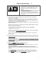
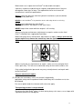
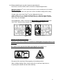
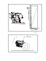
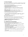
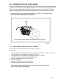
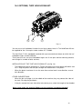
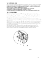
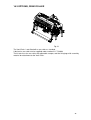
User manual and parts
handbook
Verti-Drain®
Model 7110
Serial number:
Translation of the original operating instructions
ATTENTION:
TO ENSURE SAFE USE OF THIS MACHINE AND TO BE ABLE
TO ACHIEVE THE BEST RESULTS, IT IS OF THE UTMOST
IMPORTANCE TO READ THIS USER MANUAL THOROUGHLY
BEFORE USING THE VERTI-DRAIN®.
0948 English 911.120.473
FOREWORD
Congratulations on your purchase of the Verti-Drain®. To ensure the long and safe use of
®
this Verti-Drain , it is of the utmost importance for all those who will be using it to read and
understand this user manual. Operation of this machine is not safe without full knowledge of
the content of the manual.
®
The Verti-Drain is not an independently operating machine. The user is responsible for
®
using the appropriate tractor. The user must also check the tractor/Verti-Drain combination
for safety aspects such as the noise level, adequate user instructions, and possible risk
factors.
®
The Verti-Drain is solely intended for use on lawns and other areas where grass could
grow.
On the next page you will first find the general safety instructions. Every user must know and
apply them. After this, a registration card is included. This card should be returned for
handling any future claims.
This user manual offers many instructions numbered in sequence. This sequence should be
observed. An asterisk * indicates a safety instruction. An @ indicates a tip and/or note.
All information and technical specifications provided at the moment that this
document is published are the most recent ones. Design specifications may be
changed without prior notice.
This document is a translation of the original operating instructions.
Upon request, the original operating instructions are available in Dutch.
GUARANTEE CONDITIONS
®
THIS VERTI-DRAIN IS DELIVERED WITH A WARRANTY AGAINST DEFECTS IN
MATERIALS.
THIS GUARANTEE IS VALID FOR A PERIOD OF 12 MONTHS FROM THE PURCHASING
DATE.
VERTI-DRAIN® WARRANTIES ARE SUBJECT TO THE “GENERAL CONDITIONS FOR
SUPPLY OF PLANT AND MACHINERY FOR EXPORT, NUMBER 188”, WHICH ARE
PUBLISHED UNDER THE AUSPICES OF THE UNITED NATIONS ECONOMIC
COMMISSION FOR EUROPE.
REGISTRATION CARD
For your own information, please complete the table below:
Serial number of machine
Dealer name
Purchasing date
Remarks
2
!
SAFETY INSTRUCTIONS
!
The design of the Verti-Drain® allows for safe use.
However, this is only possible if the user fully
observes the safety instructions given in this
manual.
Read and understand (Fig. 1) the manual before
starting to use the Verti-Drain.
If the machine is not used as described in the
manual, injury and/or damage to the Verti-Drain®
may result.
`
Fig. 1
(1) The Verti-Drain® is solely intended for the treatment of lawns or other areas
where grass should grow.
Any other use is considered to be incorrect use. The manufacturer accepts no
liability whatsoever with regard to damage resulting from such incorrect use; all
resulting risks are the responsibility of the user.
Correct use also includes following the manufacturer’s usage, maintenance and
repair instructions.
Before using the Verti-Drain®, inspect the area to be treated. Remove any loose
obstacles and avoid irregularities.
The Verti-Drain® was constructed according to the latest technological
knowledge and is safe to use.
Improper use, maintenance or repair of the machine may result in injury to both
the user and others. This should be avoided!
®
Always use the Verti-Drain in combination with the proper tractor as described in the
technical data.
(3) All persons whom the owner assigns to operate, maintain or repair the Verti-Drain® must
read and have completely understood the operating manual and in particular the section
Safety Instructions.
The user is responsible for a safe tractor/ Verti Drain® combination. This unit
must be tested in terms of noise, safety and ease-of-use. In addition, user’s
instructions must be prepared.
(4) The user is obliged, before using the Verti-Drain®, to
check it for visible damage and defects.
®
Any changes in the Verti-Drain (including its functioning) that may affect its safety must
be corrected immediately.
For reasons of safety, any modifications or additions to the Verti-Drain®
(with the exception of those approved by the manufacturer) are not permitted in
principle.
If any modifications have been made to the Verti-Drain®, the present CE
certificate becomes null and void and the person who made the modifications
should himself make sure a new CE certificate is granted.
3
Before each use, inspect the Verti-Drain® for loose bolts/nuts/parts.
If present, inspect the hydraulic hoses regularly and replace them if they are
damaged or show signs of wear. The replacement hoses must meet the
manufacturer’s technical specifications.
Always relieve the pressure from the hydraulic installation, if present, before
carrying out any work on it.
®
NEVER use de Verti-Drain if its protective covers and safety decals are missing.
NEVER crawl underneath the Verti-Drain®.
If you need to access the bottom, tilt the Verti-Drain®.
NEVER step off the tractor while the engine is still running.
When carrying out maintenance, adjustments or repairs, make sure the VertiDrain® is blocked from sagging/moving/sliding.
Before carrying out any maintenance, adjustments or repairs, always switch off the
tractor engine first, remove the tractor key from the ignition, and disconnect the
PTO (Fig. 2).
Fig. 2
When carrying out any maintenance or repairs, make sure to use original VertiDrain® parts only. This will ensure continued safety of the machine and its user.
Only authorised technical personnel may carry out adjustments and repair work
to the Verti-Drain®.
Keep an overview of repairs.
(5) Besides the instructions in this user manual, the generally
applicable safety and Occupational Health and Safety Act instructions must also
be followed.
For use on public roads the relevant traffic rules also apply.
Transporting persons is not permitted!
Do not use the Verti-Drain® when it is dark, during heavy rain/ storms, or on slopes with
a gradient greater than 20 degrees.
4
(6) Before embarking on any job, all persons operating the
Verti-Drain® must be familiar with its functions and operating elements.
®
Connect the Verti-Drain to the vehicle that will pull it exactly according to the instructions
(Danger of injury!)
Before driving off, make sure you have a clear view both nearby and far away.
On both sides of the Verti-Drain® on the sideboard, there are
safety stickers (Fig. 3,4,5) and on the back cover (Fig. 6) with the same meaning.
Make sure these safety stickers are always clearly visible and legible. Replace
them if they are damaged.
During operation, make sure there are NO persons in the danger area of the
Verti-Drain®, because they may be injured by moving parts. (Fig. 3).
Fig. 4
Fig. 3
Remain at least 4 metres away! (Fig. 4).
The back cover must always be closed and undamaged during operation of the
machine! (Fig. 5).
Be careful not to get pinched when opening the rear cover! (Fig. 6).
Fig. 5
Fig. 6
Be aware of the maximum lifting capacity of the towing vehicle.
Wear suitable clothing. Wear sturdy shoes with a steel cap, long trousers,
tie up long hair and do not wear loose clothing.
5
(7) Location of safety stickers. (Fig. 7).
Fig. 7
Used oil/grease is harmful to the environment; dispose of it according to locally
applicable regulations.
6
CONTENTS
Section
Description
Page
Foreword
2
Guarantee conditions
2
Registration card
2
Safety instructions
3
1.0
Technical data
8
2.0
First installation, removing the machine from the pallet
9
3.0
General parts list
10
4.0
The power take-off shaft
11
4.1
The length of the power take-off shaft
11
4.2
Use of the power take-off shaft
12
5.0
Adjusting the working depth
12
6.0
Pin angle adjustment
13
7.0
Driving speed
13
8.0
Start procedure
9.0
10.0
15
®
Operation of the Verti-Drain
15
®
Transportation of the Verti-Drain
®
16
11.0
Disconnecting the Verti-Drain
16
12.0
Troubleshooting
17
13.0
Maintenance
18
14.0
EU certificate
19
15.0
Technical information
20
15.1
The crankshaft
20
15.1.2
15.1.3
15.2
Replacement of a crank throw / crank bearing
21
Releasing crankshaft tension/torque values
Aligning an element
21
21
15.3
Tensioning the V-belt drive
22
16.0
Options, Turf hold-down kit
23
16.1
Options, pins
24
16.1.1
Solid pins
24
16.1.2
Hollow pins
25
16.2
Windrow Kit
25
16.3
Back roller
26
Parts pages
7
1.0
TECHNICAL DATA
Model
7110
Working width
1.0 m (40”)
Working depth
Up to 150 mm (6”)
Tractor speed measured at 500
rpm PTO-shaft speed
Hole separation 55 mm (2-1/8”)
Hole separation 90 mm (3-1/2”)
Hole separation 125 mm (5”)
PTO-shaft speed:
Up to 1,65 km/hr (1,03 mph)
Up to 2,70 km/hr (1,68mph)
Up to 3,75 km/hr (2,33mph)
500 rpm
Weight
340 kg (750 lbs)
Hole separation between the pins 55 mm (2-1/8”)
Hole separation in driving
direction
50 - 125 mm (2” - 5”)
Recommended tractor
13 HP with minimum lifting capacity of 410 kg
(943 lbs)
Maximum capacity
Hole separation 55 mm (2-1/8”)
Hole separation 90 mm (3-1/2”)
Hole separation125 mm (5”)
Shipping dimensions
Up to 1650 m²/hr (17760 ft²/hr)
Up to 2700 m²/hr (29062 ft²/hr)
Up to 3750 m²/hr (40365 ft²/hr)
1260 x 700 x 900 mm
(49.6” x 27.6” x 35.4”)
Maximum pin size
Three-point connection
Solid 12 x 150 mm (1/2”x 6”)
Hollow
19 x 150 mm (3/4”x 6”)
3- point CAT 1
Gearbox oil
SAE 140
Lubricant
EP 2
Standard parts
Set of solid pins 12x150 (1/2”x 6”).
Front roller
Tool tube with tools and user manual.
PTO shaft.
Adjustable legs.
Options
Solid pins
Hollow pins
Turf hold down fingers
Windrow kit
Back roller
8
2
1
3
4
Fig. 8
2.0
FIRST INSTALLATION, REMOVING THE MACHINE FROM THE
PALLET
The machine is standing vertically on the pallet. To remove the pallet and lay the machine
horizontally, carry out the following steps (see fig. 8):
1. Open the rear cover
2. Remove the PTO, PTO protective cover, pins and adjustable legs 1 from the
machine.
3. Fit adjustable legs 1 and lock them with the retaining clip supplied.
4. Fasten a cable to the lifting point
* Make sure that the cable/crane/lift can lift at least 410 kg (943 lbs).
@ Be careful that no machine parts can be bent by lifting!
5. Use the pallet to lift the machine from the ground and place it on the adjustable legs.
6. Remove the pallet by sliding it from the lower 3-point pins
* Do not crawl under the machine!!
7. Install the included PTO cover 2.
8. Attach the machine to a tractor.
* Use the correct tractor. See the specifications.
@ If the bottom 3-point connecting arms of the tractor cannot get to the
connecting pins, there is the possibility of inserting it in another hole 4.
9. Place the machine on the ground, and turn the top rod to adjust the angle of the
machine to 90 degrees.
@ this angle of 90 degrees is very important for the correct operation of the machine.
10. Set the tractor’s stabiliser to 50 mm of lateral movement.
11. Mount the pins. Grease the end that will be inserted.
12. Length of the PTO shaft, see 3.1.
9
4
8
1
9 10
11
5
12
7
6
2
3
11
Fig. 9
3.0 GENERAL PARTS LIST
Figure 9 shows some important parts:
1. Safety decal RA, read user manual before use / Toolbox with tools and manual.
2. Safety sticker 911.280.402: keep a distance of at least 4 metres from the machine. Stop
the engine before carrying out repairs or adjustments.
3. Safety decal 911.280.404, the back cover must always be closed and undamaged during
operation of the machine!
4. Safety decal 900.280.404, Be careful not to get pinched when opening the rear cover!
* Make sure all decals are clearly visible on the machine and are understood.
5. The serial number is on the inside of the machine.
6. Operating-depth indicator. Attention: the indication is based on the maximum length of
the pins.
7. Pin angle adjustment handle/indicator.
8. Three-point fastening pins.
9. PTO protective cover on the machine.
10. PTO input shaft.
11. Star button/nut for securing the back cover of the Verti-Drain®.
12. Storage legs
10
4.0 The PTO shaft
Ma
x. 3
0°
A
Ma
x. 3
0°
The PTO shaft is a very important part. It provides the driving force from the tractor and – if
installed, used, and maintained correctly – ensures safe use of the machine. The PTO shaft
has its own CE certificate. Make sure to read the PTO shaft manual. It is located on the PTO
shaft itself.
B
150m
m (6"
) min.
Fig. 10
4.1 LENGTH OF THE PTO SHAFT
The length of the PTO shaft is very important. If it is too long, it may damage the drive of the
tractor and/or the Verti-Drain®. If the overlapping length of the sleeves is, at any time, shorter
than 150 mm, the PTO shaft may be damaged.
*The length will vary when the machine is raised or if another
tractor is used.
To make sure the length of the PTO shaft is correct, after purchase or when using another
tractor, carry out the following steps: (see Fig.10)
1. Measure the distance between the PTO connection of the tractor and that of the VertiDrain, from groove to groove, when the machine is at the correct angle on the ground
and attached to the tractor.
2. Measure the distance B of the PTO at its shortest position, from locking pin to locking
bolt.
3. Split the PTO in two and remove the protective cover from both ends.
4. Both the sleeve ends and the cover ends have to be shortened: (B-A) + 75 mm (3”).
5. Debur, grease, and assemble all parts.
6. Mount the PTO on the Verti-Drain side.
7. Attach the other end of the PTO to the tractor.
8. Check the overlap of the sleeves.
*Never use the machine if the protective cover of the PTO is damaged.
Replace it first.
11
4.2 OPERATION OF THE PTO SHAFT
To ensure correct operation of the PTO, check the following items:
1. During operation, the angle of the joints must never be greater than 30 degrees.
2. The rotating points should be aligned.
3. The overlap of the sleeves must be at least 150 mm.
4. Never use the machine if the protective cover of the PTO is damaged.
5. For lubrication, see section 13.0: Maintenance.
3
1
1
3
3
2
1
2
F
Fig. 11
Fig. 12
5.0 OPERATING-DEPTH ADJUSTMENT
The operating depth can be adjusted when the machine is lifted, see fig. 11.
Loosen nuts 1 one turn on both sides of the machine.
Then turn bolt 3 in or out. Each rotation is 4 mm (0.160”). Label 2 on the side of the machine
indicates the depth setting. After having reached the correct working depth, retighten nuts 1.
@
Never adjust one side more than 4 turns. Before continuing, compensate the other
side.
@
A spanner is included in the machine’s tool tube.
@
The depth-adjustment on the decals only applies when 150 mm (6”) long pins are
used. When shorter pins are used, subtract the difference in length, compared to 150
mm (6”), from the value shown on the decals.
@
The spindle and the nut must be cleaned every 100 hours and sprayed with thin oil
that does not attract dirt, to prevent dirt from remaining on the nut.
12
6.0
PIN ANGLE ADJUSTMENT
All pins can be simultaneously adjusted with a centrally-placed handle, located on the side of
the machine, see fig. 12. Lift the machine above the ground and loosen nut 2 on both sides
of the machine. Adjust the angle by turning the handle. The angle can be read on the sticker.
Retighten the nuts.
@
@
@
@
An angle of 90 degrees means almost no draught. This is required for hollow pins
and is advised for the needle pins.
From 90 to 75 degrees means more draught. This is advised for solid pins and
depends on the ground conditions, the pin size and the client’s preference.
At 90 degrees, the pins only go straight into the ground if the machine is correctly
installed, see fig. 1. If this is not correct, force F can be produced, see fig. 12, which
will damage the machine.
The length of the assembled drawbar must be 291 mm (11.5”), which can be
calibrated using shims, see parts page.
7.0 DRIVING SPEED
The hole distance
D, fig. 13, in the driving direction is determined by the drive speed. The
Verti-Drain® does not require creep gear. If the client wants a small hole distance, however,
it must be possible to ride slowly enough, which depends on the tractor.
The input speed of the PTO shaft R may not exceed 500 rpm. If hard objects can be
expected, this speed must be reduced.
With heavier pins, other applications, or with maximum pin angle, the pin holders may float.
In this case, reduce the speed R before the pin holders are forced upward.
Fig. 13 contains a table that shows the relationship between the driving speed and the hole
distance. If the driving speed of the tractor for 500 revolutions of the PTO shaft is known, the
hole distance can be determined.
®
@ If the Verti-Drain is not correctly attached behind the tractor, see fig. 8, various PTO
shaft angles can cause vibrations in the driveline of the machine. These vibrations can
damage the machine and the holes in the ground.
@ If the PTO shaft was shortened incorrectly, or if another tractor was used, the gearbox
may be overloaded. Damage can occur.
13
Fig. 13
Fig. 14
14
8.0 START PROCEDURE
The start procedure is VERY important. If this procedure is not followed exactly as described
below, serious damage may occur to the machine. The start procedure is as follows, see fig.
14.
1.
2.
3.
4.
5.
6.
Drive to the place where you want to start.
Lower the machine until the lowest knives are almost touching the ground.
Set the tractor motor at approximately 1200 rpm.
Shift the tractor to the correct gear and drive forward (A).
Engage the PTO shaft (B).
While DRIVING forward, let the TURNING machine CAREFULLY sink into the
ground (C).7. Increase the PTO shaft speed to the maximum allowable speed.
Stopping is done as follows:
1. Decrease the motor speed to approximately 1200 rpm. Raise the
machine out of the ground
3. Disengage the PTO shaft as soon as the pins are out of the ground.
4. Raise the machine further until the pins are at least 120 mm above the ground.
5. Go to the following place and start again as described.
@ It is absolutely imperative that the above procedures are followed. If the
placed in the ground first, without a rotating PTO shaft, serious
machine can occur.
@ The machine must be lowered CAREFULLY.
@ Be careful when driving in reverse.
machine is
damage to the
While working, the front roller must be in stable contact with the ground. If the machine is
unstable, other pins must be installed or the operating depth must be adjusted.
@ The machine will be damaged if the instability is not corrected. The machine does
NOT have protection against long-duration overloading.
@ NEVER drive in reverse with the pins in, or close to, the ground.
@ Do not use a hydraulic top rod.
`
9.0 OPERATION OF THE VERTI-DRAIN®
Before the Verti-Drain® is used in the field, the following should be checked:
1. Are there any loose objects in the field? Remove these first.
2. Are there any slopes? The maximum slope this machine can work on is 20 degrees.
Always work downhill.
3. Does the ground contain cables or pipes? If so, determine their depth and set the
operating depth of the machine to 60% of this depth.
®
4. Does the ground contain hard objects? If so, use the Verti-Drain at a low PTO shaft
speed and adjust the operating depth.
5. Is there any danger of flying objects, such as golf balls, which may distract the attention
of the driver? If so, do NOT use the Verti-Drain®.
6. Is there any danger of sinking or sliding away? If so, postpone working with the VertiDrain®.
7. If the soil is frozen or very wet, the work should be postponed until the conditions are
more favourable.
8. When the soil is very compact, use shorter pins or adjust the operating depth.
15
10.0 TRANSPORT OF THE VERTI-DRAIN®
®
The user is responsible for the transport of the Verti-Drain behind the tractor when travelling
on public roads. Check the national traffic regulations. On open fields, a maximum speed of
12 km/h (8 mph) should be observed, because of the weight of the Verti-Drain®. A higher
speed may endanger the driver and/or other people and may even damage the machine.
*
When the machine is in the raised position, at least 20% of the weight of the
tractor should be supported by the front axle.
1
Fig. 15
11.0 DISCONNECTING THE VERTI-DRAIN®
The machine can be disconnected from the tractor as follows:
(see fig. 15)
1. * Check the ground where the machine is to be disconnected; this must be firm and flat.
The machine may not be able to sink/move on its own.
2. Turn adjustable legs 1 downwards and block them with the R-clips.
3. Carefully lower the machine onto the adjustable legs.
4. Lock the machine to prevent it from moving.
5. Remove the top rod.
6. Remove the PTO shaft on the tractor side.
7. Remove the lower arms from the Verti-Drain®.
*
Set the tractor motor off if people are walking around the machine and
prevent the tractor from moving!
16
12.0 TROUBLESHOOTING
Problem
Machine vibrates
Possible cause
Crankshaft turns irregularly
Heavy conditions
Solid/hollow pins
should be bent/broken.
Wrong pin
Heavy conditions
Rapid wear
Front roller is not in
stable contact with the
ground.
Wrong pins, too much
resistance
Heavy conditions
PTO breaks.
Tubes split
Damage to the
drawbars.
Bend / break
Damage to the turf.
Oval holes
Damage to the turf
Pin not secure in pin
holder.
Heavy conditions
Crankshaft problems.
Big-end nuts come loose
Solution
Machine not at 90 degrees.
Angles of the PTO joints are
different.
Joints of PTO are not in line.
Adjust the operating depth.
Use thinner/shorter pins.
If conditions are dry, water soil.
Change the pin, use shorter pin.
Use solid pins before hollow pins
to break up the ground.
Adjust the operating depth.
Use thinner/shorter pins.
If conditions are dry, water soil.
First use solid pins to break open
the ground.
Adjust the pin angle.
Change pin size.
Adjust the operating depth
accordingly.
Use different pin size.
Adjust the operating depth.
Water the soil.
PTO angles are too large.
PTO angles are not the same.
Machine not at 90 degrees.
Centre bar bent.
Bearing tubes worn.
Pins touch the ground when
driving in reverse.
Lift height not correct.
Ground too wet.
Change pin angle adjustment.
Reduce forward speed.
Adjust the operating depth.
Use thinner pins.
Use different pins.
Grind a flat area on the pins.
Adjust the pin angle.
Eliminate the vibration, see
vibration.
Crankshaft bearing worn.
Incorrectly installed after repair.
Remove, clean, use Loctite.
17
V-belts are slipping.
Hole distances not
equal
V-belt tension too low
V-belts are worn
V-belt tension too low
V-belts are worn
Adjust the V-belt tension (see
section 15.3).
Replace V-belts.
Adjust the V-belt tension (see
section 15.3).
Replace V-belts.
13.0 MAINTENANCE
Time schedule
Before each use
After first 20 operating
hours
(new or repaired)
Check point/lubricating
point
Method
Check for loose bolts/nuts.
Tighten the loose bolts/nuts
with the correct torque.
Connect the machine to the
tractor and leave the machine
running without load for five
minutes.
Look and listen for any
strange noises and
movements.
Check the oil level in the
gearbox.
If necessary, use SAE 140
Presence and legibility of safety
stickers (Fig. 7).
Replace if damaged or
missing.
Any loose parts around the
PTO.
Secure these parts so that
they cannot come too close
to the PTO.
Lubricate the PTO and roller .
Use EP 2 lubricating grease.
Check for loose bolts/nuts.
Tighten the loose bolts/nuts
with the correct torque.
Connect the machine to the
tractor and leave the machine
running without load for five
minutes.
Look and listen for any
strange noises and
movements.
Check the oil level in the
gearbox. The oil level should be Use SAE 140
at the centre of the gauge glass.
Check the transmission for oil
leaks.
Replace seals / sealing
paste.
18
Time schedule
After first 20 operating
hours
Check point/lubricating
point
Any loose parts around the
PTO.
Secure these parts so that
they cannot come too close
to the PTO.
Check V-belt tension
Adjust the V-belt tension
(see section 15.3)
Use EP 2 lubricating grease.
(new or repaired)
After every 50 operating
hours.
Method
Lubricate the PTO and roller
bearings.
Check for loose bolts/nuts.
Tighten the loose bolts/nuts
with the correct torque.
Connect the machine to the
tractor and leave the machine
running without load for five
minutes.
Look and listen for any
strange noises and
movements.
Replace the oil in the gearbox.
Use SAE 140
Check the transmission for oil
leaks.
Replace seals / sealing
paste.
Check the V-belt tension.
After every 500 operating
hours.
Replace the oil in the gearbox.
Adjust the tension if
necessary.
Use SAE 140
14.0 EU DECLARATION OF CONFORMITY
We, Redexim, Utrechtseweg 127, 3702 AC Zeist, The Netherlands, declare entirely
on our own responsibility that the product:
VERTI-DRAIN® MODEL 7110, WITH MACHINE NUMBER AS INDICATED ON THE
MACHINE AND IN THIS MANUAL,
to which this declaration relates is according to the stipulation of the 2006/42/EC
directive for machines.
Zeist, 01/10/09
A.C. Bos
Manager Operations & Logistics
Redexim Holland
19
15.0 TECHNICAL INFORMATION
6
5
4 7 3 2
1
Fig. 16
15.1 THE CRANKSHAFT
The crankshaft assembly is shown in figure 16. A more detailed drawing can be found on
the parts page.
For a 7110, the offset between the crankshaft throws in the gearbox must be 60 degrees.
15.1.2. REPLACEMENT OF A CRANK THROW / CRANK
BEARING
Replacement of a crankshaft throw is necessary when it is cracked or when the nuts
regularly come loose from the big-end. That is, if the throw bearings, the throw-bearing
fittings, or the big-end pin holes in the throw are damaged. Replace the throw / the bearing
as soon as possible, to prevent additional damage to other parts, as follows (see fig. 16):
1. Remove Big-End 2
2. Remove handles 3.
3. Remove profile shaft 4 with bearing 5.
4. Remove bearing 5 from profile shaft 4.
5. Replace the parts and assemble in the reverse order.
@ Use Loctite for nuts 6 and 7
20
15.1.3 Releasing crankshaft tension
If parts of the crankshaft have been replaced, the crankshaft may be more difficult to turn.
Pre-tension can be the cause. It is necessary to eliminate the sources of tension as follows,
see fig. 16:
1. Use a hammer to tap against the centre of the throw, starting with throw 1 located next to
the V-belt drive.
2. Feel whether the throw moves in the bearing and continue until the throw settles into
place.
3. Repeat this procedure for each adjacent throw until all of the throws have settled into
position and the crankshaft turns more easily.
@ After repairing the crankshaft, the nuts must be checked regularly for looseness.
@ Do not mount the throws on the wrong side of the machine. See the parts page for the
correct part numbers.
Timing Starting Reference Element 1
2
5
4
1
1
6
3
2
3
4
Element 1
Element 2
Element 3
Element 4
Element 5
Element 6
5
0 degrees 3.00 h
120 degrees 11.00 h
240 degrees 7.00 h
180 degrees 9.00 h
60 degrees 1.00 h
300 degrees 5.00 h
6
800Nm (590 lbf.ft.)
!!Lock washer!!
800Nm (59 lbf.ft.)
A 100Nm (73.8 lbf.ft.)
B 100Nm (73.8 lbf.ft.)
100Nm (73.8 lbf.ft.)
80 Nm (59 lbf.ft.)
100 Nm (73.8 lbf.ft.)
100 Nm (73.8 lbf.ft.)
80 Nm (59 lbf.ft.)
40 Nm (29.5 lbf.ft.)
!!Lock all Bolts/Nuts with Loctite!!
Fig. 17
15.2 ALIGNING AN ELEMENT.
If an element is no longer in line with the adjacent elements, the alignment can be corrected
as follows: (See fig. 17)
-
Loosen the four bolts/nuts A, that connect the crankshaft to the element.
-
Loosen the two bolts B, with which the element is connected to the frame.
-
Try to align the element by moving it sideways until it is in line with
the adjacent elements.
Re-tighten all the bolts and nuts.
-
@ The element can be pushed out of alignment through overloading.
@ Always realign an element whenever a throw is replaced so no extra tension is created in
the total element assembly.
@ Every pre-tension in the element assembly will reduce the life of the bearing and can also
damage other parts.
21
15.3 TENSIONING THE V-BELT DRIVE.
2
1
3
A
Fig. 18
If the Verti-Drain machine does not function properly and stands still with the pins in the
ground while the transmission is driven, it is possible that the V-belt pre-tension must be
adjusted. This works as follows, see Fig. 18:
1. Remove safety cover 2 by unscrewing nuts 2.
2. Unscrew the nut on tensioning pulley 3 and move the pulley downwards until the
correct pre-tension is reached.
3. Tighten the nut on pulley 3 well.
4. Check the V-belt tension by hanging a mass of 2.5 kg (5.5 lbs) on point A. The
extension must be 2 mm.
5. Place safety cover 2 and tighten nuts 1.
22
16.0 OPTIONS, TURF HOLD-DOWN KIT.
3
1
2
Fig. 19
You can use a turf hold-down kit when the turf layer comes loose. A Turf Hold Down Kit can
be supplied for the 12 mm pins under number 211.710.002.
The Verti-Drain 7110 is equipped standard with a pre-mounted main beam on which the turf
hold-down fingers can be mounted.
The kit consists of a set of turf hold-down fingers for 12 mm pins and the mounting material,
consisting of a number of bolts and nuts.
INSTALLATION OF THE TURF HOLD-DOWN KIT (see fig. 18):
-
The ordered set comes with plates 2. Fasten the plates to the main beam with bolt 3 and
nut 1. Align the plates with the pins through the slotted holes in the plates.
-
When the plates have been in use for some time and are bent in one direction, reverse
their direction.
OTHER SUGGESTIONS:
-
When the pins no longer sit in the middle of the machine, they may contact the sides of
the slots. Re-align the pin blocks.
-
If the pins contact the front side of the hole (during use), check the length of the drawbar.
Never crawl under the machine. Make sure the machine is properly blocked!
23
16.1 OPTIONS, PINS
Pins are essential for the correct operation of the machine. There are various pins available
for this machine; see the parts page for a complete overview. In general, the pins can be
divided into two categories: solid and hollow pins. We advise you to use only original pins
because they are completely adapted to the machine.
The pin holders have 3 x 12 mm (½”) holes in which pins can be secured.
Locking bolt A may be tightened to 40 Nm (29.5 lbf.ft.). (Fig. 20)
If the pins come out of the pin holders, grind a flat area on the mounting end of the pins.
16.1.1 SOLID PINS.
Solid pins break open compacted soil. The pin angle adjustment (see chapter 6.0)
determines the quantity of draught movement in the ground. When the angle is adjusted
from 90 to 75 degrees, the draught movement increases. With a 90 degree adjustment,
there is almost no pin movement created in the ground.
When the pins are new, they may damage the turf, in particular when the root system is
weak. First clean the pins manually or use the machine first for 10 minutes on another rough
ground surface.
When the root system is weak, try to adjust the working depth such that the pricking depth is
slightly deeper than the length of the roots. This gives the roots a chance to grow deeper.
Prick deeper the next time. By using this method, you can prevent damage to the turf and
ensure a healthy root system.
We advise you to use the solid pins with the sharp point toward the front roller. This
ensures the best pin movement into the ground. On the other hand, for weak turf, we
advise you to use the pins with the sharp point toward the rear of the machine.
A
Fig. 20
24
Always use pins with the same diameter and length. Replace a bent pin immediately. If this
is not done, the machine can become unstable. Do not use thicker and/or longer pins than
we supply.
Shorter (ground off) pins can be used when shallower pricking is desired. Be aware that the
operating depth indicated on the decal is only accurate when the maximum length of the pin
is used.
When oval holes are created, this means that there is a weak top layer with a hard layer
underneath. Use thinner pins or wait until the (wet) top layer has dried.
When top dressing must be applied, apply it before using the Verti-Drain.
When the ground is difficult to prick, water the soil first, use thinner and shorter pins, or
adjust the operating depth. If these measures are not taken, the machine will eventually be
damaged.
16.1.2 HOLLOW PINS
The ground can be mixed with hollow pins. Various sizes are available; see the parts page
for more information. The opening of the pin must be directed toward the rear of the
machine.
For hollow pins it is important that the pin angle is set to 90 degrees. The movement of the
pin in the ground is minimal and in this manner a nice “clean” hole is made. When the pin
continuously moves in the ground at an angle less than 90 degrees, the pin may eventually
break.
When top dressing must be applied, use the Verti-Drain first, remove the “cores” and then
spread the sand.
When lots of waste occurs while pricking with hollow pins, reduce the rotational speed or wet
the soil first. The waste can increase the rate of wear to your machine.
If the turf is damaged, first use solid pins to establish a healthy root system and then adjust
the operating depth.
When the hollow pins become plugged, this means that the ground is (very) compact and
solid pins must be used first to break the ground open. Wetting the soil or adjusting the
operating depth can also help solve this problem.
16.2 OPTIONS, WINDROW KIT
If hollow pins are used to prick with, cores can be removed from the soil.
The Windrow kit ensures that the cores are guided neatly together after the Verti-Drain
operation, after which they can be easily removed. The kit can be supplied under number
211.710.006
25
16.3 OPTIONS, REAR ROLLER
Fig. 21
The Verti-Drain is not fitted with a rear roller as standard.
If desired, a rear roller can be supplied under number 211.710.004.
The kit consists of a rear roller with adjustable scraper, and the fixing legs with assembly
material for attachment to the Verti-Drain.
26