1
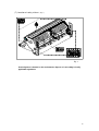
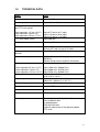
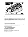
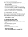
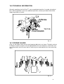
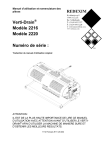
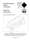
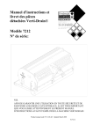
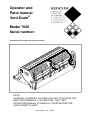
Operator and
Parts manual
Verti-Drain®
Model 7626
Serial number:
Translation of the original operating instructions
NOTE:
IN ORDER TO ENSURE THE SAFE USE AND TO ACHIEVE THE
BEST PERFORMANCE, IT IS ESSENTIAL THAT THIS
OPERATORS MANUAL IS CAREFULLY READ BEFORE THE
VERTI-DRAIN® IS USED.
0948 English 911.120.472
FOREWORD
Congratulations on your purchase of the Verti-Drain®. To ensure the long and safe use of
®
this Verti-Drain , it is of the utmost importance for all those who will be using it to read and
understand this user manual. Without full knowledge of the content, operation of this
machine is not safe.
®
The Verti-Drain is not an independently operating machine. The user is responsible for
®
using the appropriate tractor. The user must also check the tractor/Verti-Drain combination
for safety aspects such as the noise level, adequate user instructions, and possible risk
factors.
®
The Verti-Drain is solely intended for use on lawns and other areas where grass could
grow.
On the next page you will first find the general safety instructions. Every user must know and
be able to apply them. After this, a registration card is included. This card should be returned
in order to be able to handle any future claims.
This user manual offers many instructions numbered in sequence. This sequence should be
observed. An asterisk * indicates a safety instruction. An @ indicates a tip and/or note.
All information and technical specifications provided at the moment that this
document is published are the most recent ones. Design specifications may be
changed without prior notice.
This document is a translation of the original operating instructions.
Upon request, the original operating instructions are available in Dutch.
WARRANTY CONDITIONS
®
THIS VERTI-DRAIN IS DELIVERED WITH A WARRANTY AGAINST DEFECTS IN
MATERIALS.
THIS WARRANTY IS VALID FOR A PERIOD OF 12 MONTHS FROM THE PURCHASING
DATE.
VERTI-DRAIN® WARRANTIES ARE SUBJECT TO THE “GENERAL CONDITIONS FOR
SUPPLY OF PLANT AND MACHINERY FOR EXPORT, NUMBER 188”, WHICH ARE
PUBLISHED UNDER THE AUSPICES OF THE UNITED NATIONS ECONOMIC
COMMISSION FOR EUROPE.
REGISTRATION CARD
For your own information, please complete the table below:
Serial number machine
Dealer name
Date of purchase
Remarks
2
!
SAFETY INSTRUCTIONS
!
The design of the Verti-Drain® allows for safe use.
However, this is only possible if the user
completely follows the safety instructions given in
this manual.
Read and understand (Fig. 1) the manual before
beginning to use the Verti-Drain®.
If the machine is not used as described in the
manual, injury and/or damage to the Verti-Drain®
may result.
Fig. 1
®
(1) The Verti-Drain is solely intended for the treatment of lawns or other areas
where grass should grow.
Any other use is considered to be incorrect use. The manufacturer accepts no
liability whatsoever with regard to damage resulting from such incorrect use; all
resulting risks are the responsibility of the user.
Correct use also includes following the manufacturer’s usage, maintenance and
repair instructions.
Before using the Verti-Drain®, inspect the area to be treated. Remove any loose
obstacles and avoid irregularities.
®
(2) The Verti-Drain was constructed according to the latest technological
knowledge and is safe to use.
Improper use, maintenance or repair of the machine may result in injury to both
the user and others. This should be avoided!
Always use the Verti-Drain® in combination with the proper tractor as described in the
technical data.
(3) All persons whom the owner assigns to operate, maintain or repair the VertiDrain® must read and have completely understood the operating manual and in
particular the section Safety Instructions.
The user is responsible for a safe tractor/ Verti Drain® combination. This
entire unit must be tested in terms of noise, safety, and ease-of-use. In
addition, user’s instructions must be prepared.
®
(4) Before using the Verti-Drain , the user is obliged to inspect it in terms of visible
damage and defects. Any changes in the Verti-Drain® (including its functioning)
that may affect its safety must be corrected immediately. For reasons of safety, it
®
is in principle forbidden to make changes in or additions to the Verti-Drain (with
the exception of those approved by the manufacturer).
If any modifications have been made to the Verti-Drain®, the present CE
certificate becomes null and void and the person who made the modifications
should himself make sure a new CE certificate is granted.
3
Before each use, inspect the Verti-Drain® for loose bolts/nuts/parts.
If present, inspect the hydraulic hoses regularly and replace these if they are
damaged or show signs of wear. The replacement hoses must meet the
manufacturer’s technical specifications.
Always relieve the pressure from the hydraulic installation, if present, before
carrying out any work on it.
NEVER use de Verti-Drain® if its protective covers and safety decals are
missing.
NEVER crawl underneath the Verti-Drain®.
If you need to access the bottom, tilt the Verti-Drain®.
NEVER step off the tractor while the engine is still running.
When carrying out maintenance, adjustments or repairs, make sure the VertiDrain® is blocked from sagging/moving/sliding.
Before carrying out any maintenance, adjustments or repairs, always switch off the
tractor engine first, remove the tractor key from the ignition, and disconnect the
PTO (Fig. 2).
Fig. 2
When carrying out any maintenance or repairs, make sure to use original VertiDrain® parts only. This will ensure continued safety of the machine and its user.
Only authorised technical personnel may carry out adjustments and repair work
to the Verti-Drain®.
Keep an overview of repairs.
(5) In addition to the instructions in this user manual, the generally applicable
regulations with respect to safety and working conditions must be followed.
For use on public roads the relevant guidelines of the Highway Code also apply.
Transporting persons is not permitted!
Do not use the Verti-Drain® when it is dark, during heavy rain/ storms, or on slopes with
a gradient greater than 20 degrees.
4
(6) Before starting to work, all persons who will operate the Verti-Drain® must be
familiar with all its functions and controls.
Connect the Verti-Drain® to the vehicle that will pull it exactly according to the
instructions (Danger of injury!)
Before driving off, make sure you have a clear view both nearby and far away.
®
On both sides of the Verti-Drain , decals (Fig. 3,4,5) are applied to the sideboard
(Fig. 6) showing these warnings. Make sure these safety decals are always clearly
visible and legible. Replace them if they are damaged.
During operation, make sure there are NO persons in the danger area of the
Verti-Drain®, because they may be injured by moving parts. (Fig. 3)
Fig. 4
Fig. 3
Remain at least 4 metres away! (Fig. 4)
The back cover must always be closed and undamaged during operation of the
machine! (Fig. 5)
Be careful not to get pinched when opening the rear cover! (Fig. 6)
Fig. 5
Fig. 6
Be aware of the maximum lifting capacity of the towing vehicle.
Wear suitable clothing. Wear sturdy shoes with a steel tip, wear long trousers, do up
long hair and wear no loose clothing.
5
(7) Location of safety stickers. (Fig. 7)
Fig. 7
Used oil/grease is harmful to the environment; dispose of it according to locally
applicable regulations.
6
CONTENTS
Section
Description
Page
Foreword
2
Warranty conditions
2
Registration card
2
Safety instructions
3
1.0
Technical data
8
2.0
First installation, removing the machine from the pallet
9
3.0
General parts list
10
4.0
The power take-off shaft
11
4.1
The length of the power take-off shaft
11
4.2
Use of the power take-off shaft
12
4.3
Slip coupling information and maintenance
12
5.0
Adjusting the operating depth
13
6.0
Pin angle adjustment
13
7.0
Driving speed
14
8.0
Start procedure
9.0
10.0
15
®
Operation of the Verti-Drain
16
®
Transportation of the Verti-Drain
®
16
11.0
Disconnecting the Verti-Drain
16
12.0
Troubleshooting
17
13.0
Maintenance
18
14.0
EU certificate
20
15.0
Technical information
21
15.1
Torque values
21
15.2
The crankshaft
22
15.2.1
Replacement of an oil catcher
22
15.2.2
Replacement of a crank throw / crank bearing
22
15.2.3
Releasing crankshaft tension
23
15.3
Aligning an element
23
16.0
Option, Turf hold-down kit
24
16.1
Option, pins
25
16.1.1
Solid pins
25
16.1.2
Hollow pins
26
Parts pages
7
1.0
TECHNICAL DATA
Model
7626
Operating width
2.60 m (102”)
Operating depth
Up to 400 mm (16”)
Tractor speed measured at 500
rpm PTO-shaft speed
Hole separation 65 mm (2-1/2”)
Hole separation 130 mm (5”)
Hole separation 195 mm (7-1/2”)
PTO-shaft speed: (max.)
Up to 0.75 km/hr (0.47 mph)
Up to 1.50 km/hr (0.93 mph)
Up to 2.25 km/hr (1.40 mph)
Up to 500 rpm
Weight
1930 kg (4254 lbs)
Hole separation between the pins 129 mm (5”) with 24 mm (1”) holes
65 mm (2.5”) with 12 mm (1/2”) holes
Hole separation in driving
50 – 195 mm ( 2 - 7 1/2”)
direction
Recommended tractor
65 HP with minimum lifting capacity of 2300 kg
(5070 lbs)
Double-acting external hydraulic connection.
Maximum capacity
Hole separation 65 mm (2-1/2”)
Hole separation 130 mm (5”)
Hole separation 165 mm (6-1/2”)
Shipping dimensions
Up to 1950 m²/hr (20989 ft²/hr)
Up to 3900 m²/hr (41979 ft²/hr)
Up to 5850 m²/hr (62969 ft²/hr)
2800 x 1100 x 1560 mm
(110” x 43.3” x 61.4”)
Maximum pin size
Slip coupling, gearbox
Solid 24 x 400 mm (1”x 16”)
Hollow 32 x 300 mm (1-1/4”x 12”)
Maximum 1100 Nm (9680 lb.inch.)
Three-point connection
3- point CAT 2
Gearbox oil
SAE 140
Lubricant
EP 2
Standard parts
Set of solid pins 18/400 (3/4” x 16”)
Front and back roller.
3-speed gearbox.
Tool tube with tools.
Hydraulic adjustment of the operating depth.
PTO shaft.
8
7626
Verti-Dra
7626
Verti-Drain
Ve
rt
7 6 i-Dr
26 a
R
Detail A
PTO−cover
Lock Hole
Hole 4
R
Verti-Drain
7626
Pin 3
Fig. 8
2.0 FIRST INSTALLATION, REMOVING THE MACHINE FROM THE
PALLET
The machine is standing vertically on the pallet. To remove the pallet and lay the machine
horizontally, carry out the following steps (see fig. 8):
1. Open the rear cover
2. Fasten a cable to the lifting point
* Make sure that the cable/crane/lift can lift at least 2500 kg (5512 lbs)
3. Raise the machine, including the pallet, 50 mm from the ground.
4. Remove the pallet by sliding it over the bottom 3-point pins
* Do not crawl under the machine!!
5. Lower the machine slowly until the 3-point connection plates touch the ground.
6. Lower the machine further so it can run on the front roller
7. Continue to lower the machine until it rests on the front and rear rollers.
8. Install the included PTO cover.
9. Attach the machine to a tractor.
* Use the correct tractor. See the specifications.
10. Connect the hydraulic hoses to the tractor.
11. Raise the machine off the ground.
12. Open the valve on the right-front side of the machine (Detail A) by turning it anticlockwise (with the included key) to purge the hydraulic operating-depth adjustment
system of air.
13. Activate the hydraulic output of the tractor, and carefully lower the roller to remove
the air from the system.
14. Close the valve of the right-front side of the machine (Detail A) by turning it clockwise
(with the included key).
When the system still contains air repeat point 13 and 14 to remove this.
The system is now free of air and ready for use.
15. Remove the locking pins for the rear roller. Put pins 3 in hole 4.
16. Lower the machine to the ground, and turn the top rod to adjust the angle of the
machine to 90 degrees.
@ this angle of 90 degrees is very important for the correct operation of the machine.
17. Set the tractor’s stabiliser to 100 mm lateral movement.
18. Mount the pins. Grease the end that will be inserted.
19. Length of the PTO shaft, see 3.1.
9
Fig. 9
3.0 GENERAL PARTS LIST
Figure 9 shows a number of important parts:
1. Safety decal RA, read user manual before use / Toolbox with tools and manual.
2. Safety decal 911.280.402, keep a distance of at least 4 metres from the machine. Stop
the engine before carrying out repairs or adjustments.
3. Safety decal 911.280.404, the back cover must always be closed and undamaged during
operation of the machine!
4. Safety decal 900.280.404, Be careful not to get pinched when opening the rear cover!
* Make sure all decals are clearly visible on the machine and are understood.
5. The serial number is on the inside of the machine.
6. Hydraulic adjustment of the operating depth.
7. Operating-depth indicator. Attention: the indication is based on the maximum length of
the pins.
8. Pin angle adjustment spindles.
9. Rubber stops for support of the rear cover in the opened position.
10. Support guide for the rear roller.
11. Locking pin for the rear roller. Lock only when the machine is not in use or when the
roller is lifted from the ground with hollow pins.
12. 3-point fastening.
13. PTO protective covers on the machine.
14. PTO input shaft. Slip coupling must be attached to this shaft.
15. Adjustable back-roller scraper.
16. Star button/nut for securing the back cover of the Verti-Drain®.
17. Hydraulic connection to towing vehicle.
18. Pin angle adjustment indicator.
19. Air-purge valve for hydraulic operating-depth adjustment.
10
4.0 The PTO shaft
The PTO shaft is a very important part. It provides the driving force from the tractor and – if
installed, used, and maintained correctly – ensures safe use of the machine. The PTO shaft
has its own CE certificate. Make sure to read the PTO shaft manual. It is located on the PTO
shaft itself.
Fig. 10
4.1 LENGTH OF THE PTO SHAFT
The length of the PTO shaft is very important. If it is too long, it may damage the drive of the
tractor and/or the Verti-Drain®. If the overlapping length of the sleeves is, at any time, shorter
than 150 mm, the PTO shaft may be damaged.
*The length will vary when the machine is raised or if another tractor is used.
To make sure the length of the PTO shaft is correct, after purchase or when using another
tractor, carry out the following steps: (see Fig.10)
1. Measure the distance between the PTO connection of the tractor and that of the VertiDrain, from groove to groove, when the machine is at the correct angle on the ground
and attached to the tractor.
2. Measure the distance B of the PTO at its shortest position, from locking pin to locking
bolt.
3. Split the PTO in two and remove the protective cover from both ends.
4. Both the sleeve ends and the cover ends have to be shortened: (B-A) + 75 mm (3”).
5. Debur, grease, and assemble all parts.
6. Attach the PTO with the slip-connection side facing the Verti-Drain.
*The torque of the locking bolt must be 80 Nm (9700 lb.in.) and must be checked
every 40 hours.
7. Attach the other end of the PTO to the tractor.
8. Check the overlap of the sleeves.
*Never use the machine if the protective cover of the PTO is damaged.
Replace it first.
11
4.2 OPERATION OF THE PTO SHAFT
To ensure correct operation of the PTO, check the following items:
1. During operation, the angle of the joints must never be greater than 30 degrees.
2. The rotating points should be aligned.
3. The overlap of the sleeves must be at least 150 mm.
4. Never use the machine if the protective cover of the PTO is damaged.
5. For lubrication, see section 13.0: Maintenance.
4.3 SLIP COUPLING INFORMATION AND MAINTENANCE
The slip coupling will protect your machine from damager if used and maintained properly.
The following items are important:
1. The length of the spring is normally adjusted to 33 mm (1.300”).
2. When the slip coupling slips, the bolts/nuts may be turned a quarter turn at a time until
the minimum spring length of 31.5 mm (1.250”) has been reached. Further compression
will overload the machine.
@ When the bolts/nuts are over-tightened, the machine will eventually be damaged
or dangerous situations can occur.
3. The slip coupling must be receive monthly maintenance. Do this as follows:
-
-
Remove the upper PTO cover from the machine.
Loosen all bolts/nuts 2 turns.
Run the machine in the field at a very low speed.
If the coupling slips, stop after 10 seconds.
If the coupling does not slip, loosen the bolts further or proceed to the (annual)
maintenance.
(see point 4 below).
Once the coupling has slipped, retighten all the bolts/nuts to the point at which the slip
coupling functions properly again.
* Do not immediately retighten it to the previous setting.
4. Annual maintenance:
- Remove the PTO from the machine.
- Carefully check all parts of the PTO.
- Replace all parts that are damaged.
- Disassemble the slip coupling by removing all the bolts/nuts that hold the springs
together; this should cause the slip coupling to fall apart.
- Lay out all the parts and check them carefully. If any parts are damaged or worn, replace
them.
- Clean all parts that interlock or engage.
- Reassemble all the parts and tighten the bolts and nuts until the springs are adjusted to
33 mm (1.3”).
- Grease both sleeves and reassemble the two PTO halves.
- Reassemble the PTO and mount it on the machine.
- If necessary, adjust the springs of the slip coupling as described previously.
@ The slip coupling protects the machine from short-duration overloading, if properly
adjusted. Long-duration overloading will damage the machine. The slip coupling
provides no protection for this. Do not overload your machine.
12
Fig. 11
Fig. 12
5.0 OPERATING-DEPTH ADJUSTMENT
The operating depth can be adjusted when the machine is raised (before start of
use) or during operation in the ground when the machine is in use, see fig. 11.
The machine is equipped with a hydraulic operating-depth adjustment that can be
operated from the tractor by activating the hydraulic output of the tractor.
The label (1) on the side of the machine indicates the depth setting.
@ Make sure that both sides of the machine raise or lower evenly.
If not, stop the movement immediately to prevent damage to the machine.
To remove trapped air from the hydraulic operating-depth adjustment, see chapter 2.0
points 12 through 14.
@ The depth-adjustment on the decals only applies when 400 mm (16”) long pins are used.
When shorter pins are used, subtract the difference in length, compared to 400 mm
(16”), from the value shown on the decals.
6.0 PIN ANGLE ADJUSTMENT
All pins can simultaneously be adjusted with 2 handles, one of which is located on the front
of the machine; see fig. 12. Lift the machine above the ground and loosen counter nut 2 on
both sides of the machine. Adjust the angle by turning the handle 3. The angle can be read
on indicator 4. Then retighten counter nut 2.
@ An angle of 90 degrees means almost no draught. This is required for hollow pins and is
advised for the 8 mm (5/16”) pins.
@ From 90 to 65 degrees means more draught. This is advised for solid pins and is
dependent of the ground conditions, the pin size and the client’s preference.
@ At 90 degrees, the pins only go straight into the ground if the machine is correctly
installed, see fig. 8. If this is not correct, force F can be produced, see fig. 12, which will
damage the machine.
@ The length of the assembled drawbar must be 595 mm (23.4”), which can be
calibrated using shims. (see parts page)
13
Fig. 13
7.0 DRIVING SPEED
The hole distance
D, fig. 13, in the driving direction is determined by the drive speed. The
Verti-Drain® does not require creep gear. If the client wants a small hole distance, however,
it must be possible to ride slowly enough, which depends on the tractor.
The gearbox has three positions: 1, 2 and 3. The higher the number, the faster the
crankshaft turns. The input speed of the PTO shaft R may not exceed 500 rpm. If hard
objects can be expected, this speed must be reduced.
With heavier pins, other applications, or with maximum pin angle, the pin holders may float.
In this case, reduce the speed R before the pin holders are forced upward.
In fig. 13 is a table that shows the relationship between the driving speed, the gearbox speed
and the hole distance. If the driving speed of the tractor for 500 revolutions of the PTO shaft
is known, the hole distance can be determined for the different gears.
®
@ If the Verti-Drain is not correctly attached behind the tractor, see fig. 8, various PTO
shaft angles can cause vibrations in the driveline of the machine. These vibrations can
damage the machine and the holes in the ground.
@ If changing gears is difficult, the crankshaft should be turned a little.
@ If the PTO shaft was shortened incorrectly, or if another tractor was used, the gearbox
may be overloaded. Damage can occur.
* If the gearbox is shifted, the tractor motor must be shut off and the tractor /
Verti-Drain® combination must be blocked to prevent it from driving/rolling away.
14
Fig. 14
8.0 START PROCEDURE
The start procedure is VERY important. If this procedure is not followed exactly as described
below, serious damage may occur to the machine. The start procedure is as follows, see fig.
14.
1.
2.
3.
4.
5.
6.
Ride to the area where you want to begin.
Lower the machine until the lowest knives are almost touching the ground.
Set the tractor motor at approximately 1200 rpm.
Shift the tractor to the correct gear and drive forward (A).
Engage the PTO shaft (B).
While DRIVING forward, let the TURNING machine CAREFULLY sink into the ground
(C).
7. Increase the PTO shaft speed to the maximum allowable speed.
Stopping is done as follows:
1. Decrease the motor speed to approximately 1200 rpm.
2. Raise the machine out of the ground
(with the hydraulic depth adjustment or with the lifting device of the tractor).
3. Disengage the PTO shaft as soon as the pins are out of the ground.
4. Raise the machine further until the pins are at least 120 mm above the ground.
5. Go to the following location and begin again as described.
@ It is absolutely imperative that the above procedures are followed. If the
placed in the ground first, without a rotating PTO shaft, serious
machine can occur.
@ The machine must be lowered CAREFULLY.
@ Be careful when driving in reverse.
machine is
damage to the
While working, the front roller must be in stable contact with the ground. If the machine is
unstable, other pins must be installed or the operating depth must be adjusted.
@ The machine will be damaged if the instability is not corrected. The machine does
NOT have protection against long-duration overloading.
@ NEVER drive in reverse with the pins in, or close to, the ground.
@ Do not use a hydraulic top rod.
15
9.0 OPERATION OF THE VERTI-DRAIN®
Before the Verti-Drain® is used in the field, the following should be checked:
1. Are there any loose objects in the field? Remove these first.
2. Are there any slopes? The maximum slope that can be worked with this machine is 20
degrees. Always move downhill.
3. Does the ground contain cables or pipes? If so, determine their depth and set the
operating depth of the machine to 60% of this depth.
®
4. Does the ground contain hard objects? If so, use the Verti-Drain at a low PTO shaft
speed and adjust the operating depth.
5. Is there any danger of flying objects, such as golf balls, which may distract the attention
®
of the driver? If so, do NOT use the Verti-Drain .
®
6. Is there any danger of sagging or sliding? If so, postpone working with the Verti-Drain .
7. If the soil is frozen or very wet, the treatment should be postponed until the
circumstances are more favourable.
8. When the soil is very compact, use shorter pins or adjust the operating depth.
10.0 TRANSPORT OF THE VERTI-DRAIN®
The user is responsible for the transport of the Verti-Drain® behind the tractor when travelling
on public roads. Check the national traffic regulations. On open fields, a maximum speed of
12 km/h (8 mph) should be observed, because of the weight of the Verti-Drain®. A higher
speed may endanger the driver and/or other people and may even damage the machine.
* When the machine is in the raised position, at least 20% of the weight of the tractor
should be supported by the front axle.
11.0 DISCONNECTING THE VERTI-DRAIN®
The machine can be disconnected from the tractor as follows:
1. Open the rear cover.
2. Turn the crankshaft until both central pin holders right/left of the gearbox are in their top
positions.
3. Fold up all the other pin holders.
4. Set the machine with both rollers on solid ground.
5. Lock the rear guide with pin 3, see fig. 8.
6. Block the front and rear rollers from rolling away.
7. Remove the top rod.
8. Remove the PTO shaft on the tractor side.
9. Remove the lower arms of the tractor from the Verti-Drain®.
* Set the tractor motor off if people are walking around the machine and
prevent the tractor from moving!
* When storing the machine for a long period, it is recommended NOT to fold
up the pins in view of the life span of the of the shock-absorber springs.
16
12.0 TROUBLESHOOTING
Problem
Machine vibrates.
Possible cause
Crankshaft turns irregularly
Heavy conditions
Solid/hollow pins
bend/break.
Wrong pin
Heavy conditions
Rapid wear
Front roller is not in
stable contact with the
ground.
Wrong pins, too much
resistance
Heavy conditions
PTO breaks.
Slip coupling breaks often
Tubes split
Damage to the
drawbars.
Bend / break
Damage to the turf.
Oval holes
Damage to the turf
Pin not secure in pin
holder.
Heavy conditions
Solution
Machine not at 90 degrees.
Angles of the PTO joints are
different.
Joints of PTO are not in line.
Adjust the operating depth.
Use thinner/shorter pins.
If conditions are dry, water soil.
Change the pin, use shorter pin.
Use solid pins before hollow pins
to break up the ground.
Adjust the operating depth.
Use thinner/shorter pins.
If conditions are dry, water soil.
First use solid pins to break open
the ground.
Adjust the pin angle.
Change pin size.
Adjust the operating depth
accordingly.
Use different pin size.
Adjust the operating depth.
Water the soil.
Do not do all the work at one time.
Check adjustment.
Replace friction plates.
Clean the inside of the coupling.
PTO angles are too large.
PTO angles are not the same.
Machine not at 90 degrees.
Centre bar bent.
Bearing tubes worn.
Pins touch the ground when
driving in reverse.
Lift height not correct.
Ground too wet.
Change pin angle adjustment.
Reduce forward speed.
Adjust the operating depth.
Use thinner pins.
Use different pins.
Grind a flat area on the pins.
Adjust the pin angle.
17
Crankshaft problems.
Big-end nuts come loose
Eliminate the vibration, see
vibration.
Crankshaft bearing worn.
Incorrectly installed after repair.
Remove, clean, use Loctite.
Rear roller vibrates.
Rear roller locked
Rear roller is raised when
pricking with hollow pins
Unlock it.
Change the rotational speed of
the PTO.
Set roller freely on the ground.
Change the machine adjustments.
Heavy conditions
Front roller does not
lower properly or
evenly.
Air in hydraulic operatingdepth system
Bleed air from the hydraulic
operating-depth system.
(See chapter 2.0 points 12
through 14)
13.0 MAINTENANCE
Time schedule
Before each use
Check point /
lubricating point
Method
Check for loose bolts/nuts.
Tighten the loose bolts/nuts
with the correct torque.
Connect the machine to the
tractor and leave the machine
running without load for five
minutes.
Look and listen for any
strange noises and
movements.
Check the oil level in the
Use SAE 140.
gearbox. The oil level should be
at the centre of the gauge glass.
Check the hydraulic components Repair any leaks/damage.
for leaks/damage.
Presence and legibility of safety
decals. (Fig. 7).
Replace these if damaged or
missing.
Any loose parts around the
PTO.
Secure these parts so that
they cannot come too close
to the PTO.
18
Time schedule
After first 20 operating
hours
(new or repaired)
Check point /
lubricating point
Method
Lubricate the PTO, roller
bearings and crankshaft
bearings.
Use EP 2 lubricating grease.
Check for loose bolts/nuts.
Tighten the loose bolts/nuts
with the correct torque.
Connect the machine to the
tractor and leave the machine
running without load for five
minutes.
Look and listen for any
strange noises and
movements.
Use SAE 140.
Check the oil level in the
gearbox. The oil level should be
at the centre of the gauge glass.
Check the hydraulic components Repair any leaks/damage.
for leaks/damage.
After every 50 operating
hours.
Check the transmission for oil
leaks.
Replace seals / sealing
paste.
Any loose parts around the
PTO.
Secure these parts so that
they cannot come too close
to the PTO.
Use EP 2 lubricating grease.
Lubricate the PTO, roller
bearings and crankshaft
bearings.
Check for loose bolts/nuts.
Tighten the loose bolts/nuts
with the correct torque.
Connect the machine to the
tractor and leave the machine
running without load for five
minutes.
Look and listen for any
strange noises and
movements.
Replace the oil in the gearbox.
Use SAE 140.
Check the hydraulic components Repair any leaks/damage.
for leaks/damage.
After every 500 operating
hours.
Check the transmission for oil
leaks.
Replace seals / sealing
paste.
Replace the oil in the gearbox.
Use SAE 140.
19
14.0 EU DECLARATION OF CONFORMITY
We, Redexim, Utrechtseweg 127, 3702 AC Zeist, The Netherlands, declare entirely
on our own responsibility that the product:
®
VERTI-DRAIN MODEL 7626, WITH MACHINE NUMBER AS INDICATED ON THE
MACHINE AND IN THIS MANUAL,
to which this declaration relates is according to the stipulation of the 2006/42/EC
directive for machines.
Zeist, 01/10/09
A.C. Bos
Manager Operations & Logistics
Redexim Holland
20
15.0 TECHNICAL INFORMATION
Generally speaking, the Verti-Drain® is not a complicated machine. A number of technical
items will be explained. If you have additional questions, contact your dealer who will be
happy to provide assistance.
Fig. 15
15.1 TORQUE VALUES
In fig. 15, the torque values for the most important bolts/nuts are shown. The bolts and nuts
for which no values are given must be tightened with the same torque as similar bolts and
nuts. When bolts and nuts come loose, Loctite may be used to prevent this from occurring
again.
Fig. 16
21
15.2 THE CRANKSHAFT
The crankshaft assembly is shown in figure 16. A more detailed drawing can be found on
the parts page.For a 7626, the offset between the crankshaft throws in the gearbox must
be 36 degrees.
15.2.1 REPLACEMENT OF AN OIL CATCHER
A top view of the crankshaft assembly is shown in figure 16. Proceed as follows to replace
an oil catcher in the gearbox:
1. Remove nuts II and IV, which may be very tight if fastened with Loctite. Heat may help.
2. Remove the big-end V after the big-end pin XI has been removed.
3. Remove cap III by unscrewing all the bolts/nuts.
4. Slide throw VI from the gearbox by lightly tapping in the middle with a hammer until the
big-end pin VII comes free.
5. Turn throw VI and slide big-end IX from the big-end pin VII.
6. Remove nut VIII and remove “handle” X after marking its position.
7. Remove the oil catcher with a screwdriver.
8. Clean the area / remove all oil and grease.
9. Install the new oil catcher.
10. Clean “handle” X and seal the splines with a silicone sealant.
11. Mount the “handle” in the correct position.
12. Fill the area between the “handle” and the shaft with silicone sealant.
13. Install a new lock plate and nut VIII. For the nut, also use Loctite.
14. Tighten nut VIII with the torque indicated in figure 15.
15. Install the remaining parts in reverse order.
16. If the crankshaft does not run smoothly, see 15.2.3 for additional instructions.
15.2.2. REPLACEMENT OF A CRANK THROW / CRANK
BEARING
Replacement of a crankshaft throw is necessary when it is cracked or when the nuts
regularly come loose from the big-end. That is, if the throw bearings, the throw-bearing
fittings, or the big-end pin holes in the throw are damaged. Replace the throw / the bearing
as soon as possible, to prevent additional damage to other parts, as follows (see fig. 16):
1. Remove the big-end pin nuts IV (or II) from both big-end pins that are attached to the
throw.
2. Remove the big-end pins so the big-end can be slid to one side (Note: this will not be
possible with the big-end (pin) next to the gearbox).
3. Remove the throw-bearing caps III.
4. Tap throw IV and the bearing sideways out of the frame by striking the middle of the
throw with a hammer.
5. Carefully remove the bearing from the throw.
6. After re-installing the throw and/or bearing, re-install the parts in the same order in
which they were removed. Use Loctite where indicated in figure 15.
7. If the crankshaft is more difficult to turn, see 15.2.3.
22
15.2.3 Releasing crankshaft tension
If parts of the crankshaft have been replaced, the crankshaft may be more difficult to turn.
Pre-tension can be the cause. It is necessary to eliminate the sources of tension as follows,
see fig. 16:
1. Use a hammer to tap the centre of the throw next to the gearbox, alternating between the
left and right side.
2. Feel whether the throw moves in the bearing and continue until the throw settles into
place.
3. Repeat this procedure for each adjacent throw until all of the throws have settled into
position and the crankshaft turns more easily.
@ After repairing the crankshaft, the nuts must be checked regularly for looseness, see
12.0.
@ Do not mount the throws on the wrong side of the machine. See the parts page for the
correct part numbers.
15.3 ALIGNING AN ELEMENT.
If an element is no longer in line with the adjacent elements, the alignment can be corrected
as follows: (See fig. 15)
-
Loosen the four bolts/nuts A, that connect the crankshaft to the element.
-
Loosen the two bolts B, with which the element is connected to the frame.
-
Try to align the element by moving it sideways until it is in line with the adjacent
elements.
Re-tighten all the bolts and nuts.
-
@ The element can be pushed out of alignment through overloading.
@ Always realign an element whenever a throw is replaced so no extra tension is created in
the total element assembly.
@ Every pre-tension in the element assembly will reduce the life of the bearing and can also
damage other parts.
23
16.0 OPTIONS, TURF HOLD-DOWN KIT.
Fig. 18
You can use a turf hold-down kit when the turf layer comes loose. For the 7626, two sets are
available. One with plates for the holes of 12 mm pins (part # 211.762.002) of the pin block
and one with plates for the holes of 24 mm pins of the pin block.
The Verti-Drain 7626 is equipped standard with a pre-mounted main beam on which the turf
hold-down fingers can be mounted.
The kit consists of a set of turf hold-down fingers for 12 or 24 mm pins and the mounting
material consisting of a number of bolts and nuts.
INSTALLATION OF THE TURF HOLD-DOWN KIT (see fig. 18):
-
The ordered set comes with plates 4 or 5. Mount the plates with bolt 3 and nut 2 on main
beam 1. Align the plates with the pins through the slotted holes in the plates.
-
When the plates have been in use for some time and are bent in one direction, reverse
their direction.
OTHER SUGGESTIONS:
-
When the pins no longer sit in the middle of the machine, they may contact the sides of
the slots. Re-align the pin blocks.
-
If the pins contact the front side of the hole (during use), check the length of the drawbar.
* Never crawl under the machine. Make sure the machine is properly blocked!
24
16.1 OPTIONS, PINS
Pins are essential for the correct operation of the machine. There are various pins available
for this machine; see the parts page for a complete overview. In general, the pins can be
divided into two categories: solid and hollow pins. We advise you to use only original pins
because they are completely adapted to the machine.
In fig. 12, various pin combinations are shown. The pin holders have 5 x 12 mm (½”) holes
and 2 x 24 mm (1”) holes in which pins can be secured. The locking bolt A may be tightened
to 40 Nm (30 lbs.ft.) and locking bolt B to 70 Nm (50 lbs.ft.) (See Fig. 19). If the pins still
come out of the pin holders, grind a flat area on the mounting end of the pins.
16.1.1 SOLID PINS.
Solid pins break open compacted soil. The pin angle adjustment (see section 6.0)
determines the quantity of draught movement in the ground. When the angle is adjusted
from 90 to 65 degrees, the draught movement increases. With a 90 degree adjustment,
there is almost no pin movement created in the ground.
When the pins are new, they may damage the turf, in particular when the root system is
weak. First clean the pins manually or use the machine first for 10 minutes on another rough
ground surface.
If the root system is weak, try not to break the ground open deeper than the length of the
roots. Adjust the operating depth so the prick depth is approximately 75 mm (3”) deeper than
the length of the roots. This gives the roots a chance to grow deeper. Prick deeper the next
time. By using this method, you can prevent damage to the turf and ensure a healthy root
system.
We advise you to use the solid pins with the sharp point toward the front roller. This
ensures the best pin movement into the ground. On the other hand, for weak turf, we
advise you to use the pins with the sharp point toward the rear roller.
The rear roller must not be locked.
Fig. 19
25
Always use pins with the same diameter and length. Replace a bent pin immediately. If this
happens, the machine can become unstable. Do not use thicker and/or longer pins than we
supply.
Extra reinforcement plates are delivered standard with the machine. It is advisable to use
these for solid pins to increase the lifespan of the tine holders.
Shorter (ground off) pins can be used when shallower pricking is desired. Be aware that the
operating depth indicated on the decal is only accurate when the maximum length of the pin
is used.
When oval holes are created, this means that there is a weak top layer with a hard layer
underneath. Use thinner pins or wait until the (wet) top layer has dried.
When top dressing must be applied, apply it before using the Verti-Drain.
When the ground is difficult to prick, water the soil first, use thinner and shorter pins, or
adjust the operating depth. If these measures are not taken, the machine will eventually be
damaged.
When large pins are used, the pin holders may be forced out of balance. If this occurs,
reduce the PTO speed immediately, otherwise damage will occur when the pins contact the
rear roller.
16.1.2 HOLLOW PINS
The ground can be mixed with hollow pins. Various sizes are available; see the parts page
for more information. The opening of the pin must be directed toward the rear of the
machine.
For hollow pins it is important that the pin angle is set to 90 degrees. The movement of the
pin in the ground is minimal and in this manner a nice “clean” hole is made. When the pin
continuously moves in the ground at an angle less than 90 degrees, the pin may eventually
break.
When top dressing must be applied, use the Verti-Drain first, remove the “cores” and then
spread the sand.
When lots of waste occurs while pricking with hollow pins, reduce the rotational speed or wet
the soil first. The waste can increase the rate of wear to your machine.
If the turf is damaged, first use solid pins to establish a healthy root system and then adjust
the operating depth.
The rear roller can be raised from the ground and locked with the locking pins so it does not
flatten the cores. However, when the machine is a bit unstable and the rear roller begins to
vibrate, it is better to keep the rear roller on the ground.
When the hollow pins become plugged, this means that the ground is (very) compact
and solid pins must be used first to break the ground open. Wetting the soil or
adjusting the operating depth can also help solve this problem.
26