1
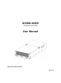
XJ3000-4603S SSG-JBSA21S-4603-S9RS User Manual SAS/SATA JBOD SERIES Rev.1.0 XJ3000-4603S User Manual Contents Preface........................................................................................................................................ 2 Before You Begin ........................................................................................................................ 3 SAFETY PRECAUTIONS ........................................................................................................ 3 SYSTEM COMPONENTS ...................................................................................................... 5 1. Introduction ....................................................................................................................... 6 1.1. Front Panel ............................................................................................................. 6 1.2. Rear Panel ............................................................................................................... 8 1.3. 8088 with Zoning Configuration and 8088 port definition .................................... 8 2. Hardware Installation ...................................................................................................... 11 2.1 2.2 3. Removing and Installing top cover ....................................................................... 11 Removing/installing a drive tray, installing a hard disk drive, and drive map checking ................................................................................................................ 12 2.3 Removing and Installing a PSU Module................................................................ 15 2.4 Removing and Installing a Fan Module ................................................................ 16 2.5 Removing and Installing Expander module .......................................................... 16 2.6 Removing and Installing HDD backplane module ................................................ 17 2.7 Installing Slide Rail ................................................................................................ 18 Sub-system configuration Setup ..................................................................................... 21 3.1. Utility Set up on Host ........................................................................................... 21 3.2. RS232 connect Host to JBOD ................................................................................ 24 3.3. 3.4. 3.5. 3.6. 3.7. 3.8. 3.9 3.10 3.11 Zoning configuration set up ................................................................................. 24 Configure zone count ........................................................................................... 26 Check the Firmware, SAS Address, and MFG revisions........................................ 28 Remote (Power on/off the enclosure via RS232)................................................. 30 Change temperature sensor threshold setting via Hub port ............................... 32 Firmware and MFG update procedure ................................................................. 34 Identify the enclosure .......................................................................................... 41 Power off the enclosure via in-band SAS ............................................................. 45 Power Saving on SAS Drive ................................................................................... 47 1 XJ3000-4603S User Manual Preface Copyright No part of this publication may be reproduced, stored in a retrieval system, or transmitted in any form or by any means, electronic, mechanical, photo-static, recording or otherwise, without the prior written consent of the manufacturer. Trademarks All products and trade names used in this document are trademarks or registered trademarks of their respective holders. Changes The material in this document is for information purposes only and is subject to change without notice. Warning: • • • A shielded-type power cord is required in order to meet FCC emission limits and also to prevent interference to the nearby radio and television reception. It is essential that only the supplied power cord be used. Use only shielded cables to connect I/O devices to this equipment. You are cautioned that changes or modifications not expressly approved by the party responsible for compliance could void your authority to operate the equipment. Disclaimer: AIC shall not be liable for technical or editorial errors or omissions contained herein. The information provided is provided "as is" without warranty of any kind. To the extent permitted by law, neither AIC or its affiliates, subcontractors or suppliers will be liable for incidental, special or consequential damages including downtime cost; lost profits; damages relating to the procurement of substitute products or services; or damages for loss of data, or software restoration. The information in this document is subject to change without notice. 2 XJ3000-4603S User Manual Before You Begin SAFETY PRECAUTIONS Before getting started, please read the following important cautions: • All cautions and warnings on the equipment or in the manuals should be noted. • Most electronic components are sensitive to electrical static discharge. Therefore, be sure to ground yourself at all times when installing the internal components. • Use a grounding wrist strap and place all electronic components in static-shielded devices. Grounding wrist straps can be purchased in any electronic supply store. • Be sure to turn off the power and then disconnect the power cords from your system before performing any installation or servicing. A sudden surge of power could damage sensitive electronic components. • Do not open the system’s top cover. If opening the cover for maintenance is a must, only a trained technician should do so. Integrated circuits on computer boards are sensitive to static electricity. Before handling a board or integrated circuit, touch an unpainted portion of the system unit chassis for a few seconds. This will help to discharge any static electricity on your body. • Place this equipment on a stable surface when install. A drop or fall could cause injury. • Please keep this equipment away from humidity. • Carefully mount the equipment into the rack, in such manner, that it won’t be hazardous due to uneven mechanical loading. • This equipment is to be installed for operation in an environment with maximum ambient temperature below 35°C. • The openings on the enclosure are for air convection to protect the equipment from overheating. DO NOT COVER THE OPENINGS. • Never pour any liquid into ventilation openings. This could cause fire or electrical shock. • Make sure the voltage of the power source is within the specification on the label when connecting the equipment to the power outlet. The current load and output power of loads shall be within the specification. • This equipment must be connected to reliable grounding before using. Pay special attention to power supplied other than direct connections, e.g. using of power strips. • Place the power cord out of the way of foot traffic. Do not place anything over the power cord. The power cord must be rated for the product, voltage and current marked on the product’s electrical ratings label. The voltage and current rating of the cord should be greater than the voltage and current rating marked on the product. 3 XJ3000-4603S User Manual • If the equipment is not used for a long time, disconnect the equipment from mains to avoid being damaged by transient over-voltage. • Never open the equipment. For safety reasons, only qualified service personnel should open the equipment. • If one of the following situations arise, the equipment should be checked by service personnel: The power cord or plug is damaged. Liquid has penetrated the equipment. The equipment has been exposed to moisture. The equipment does not work well or will not work according to its user manual. The equipment has been dropped and/or damaged. The equipment has obvious signs of breakage. Please disconnect this equipment from the AC outlet before cleaning. Do not use liquid or detergent for cleaning. The use of a moisture sheet or cloth is recommended for cleaning. Product features and specifications are subject to change without notice. 4 XJ3000-4603S User Manual SYSTEM COMPONENTS Before removing the subsystem from the shipping carton, visually inspect the physical condition of the shipping carton. Exterior damage to the shipping carton may indicate that the contents of the carton are damaged. If any damage is found, do not remove the components; contact the dealer where the subsystem was purchased for further instructions. Before continuing, first unpack the subsystem and verify that the contents of the shipping carton are all there and in good condition. Your new JBOD System includes: No Item Description Quantity 1 Enclosure (Power supply, fan, 60 HDD tray included) 1 2 3 Power cord 4 DB9-PLUG/RS232 cable 1 Spare tray 1 6#32 Flat head x 5mm screws 125 Sliding Rail 1 Set 4 5 6 If any items are missing, please contact your authorized reseller or sales representative. 5 XJ3000-4603S User Manual 1. Introduction XJ3000-4603S is a 4U rackmount chassis with 60 x 3.5”HDD hot swap bay and dual expander SATA JBOD, which is a high density, availability and scalable storage product. The 4U-60 JBOD supports T10 zoning function and can be shared by up to 4 servers. 1.1. Front Panel 1 60 LED to show HDD status: ○ Behavior LED Status Power on Blue Access Blinking blue Locate Blinking purple Fault Purple 2 Power Fault, Temperature, Fan, Power, and Expander LEDs ○ Power Fault LED Behavior LED Status Normal Off Failed Red 6 XJ3000-4603S User Manual Temperature LED Behavior LED Status Normal Off Failed Red Fan LED Behavior LED Status Normal Off Failed Red Power LED Behavior LED Status Power on Blue Power fault Purple Power off Off Secondary Expander Module LED Behavior LED Status Connected Blue Identify Blinking blue Not Connected Off Primary Expander Module LED Behavior LED Status Connected Blue Identify Blinking blue Not Connected Off 7 XJ3000-4603S User Manual 1.2. Rear Panel 1 ○ 2 ○ 3 ○ 4 ○ 2 x 8038 hot-swap PWM fans 2 x 6038 hot-swap fans Dual expanders 8 x 8088 Mini SAS ports 5 1890W 3+1 redundant 80+ HRP ○ 1.3. 8088 with Zoning Configuration and 8088 port definition WARNING: Adaptec (6445/6405/5445/5085/51645), ATTO (R380/R680), 3ware (9750-8e) SAS cards cannot work T10 zoning function with 4U60. LSI HBA/RAID card can work T10 zoning well with 4U60 JBOD. There are 3 kinds of zoning options that can be implemented by Command Line Interface operation (see Paragraph 3.3: Zoning configuration set up). By using the zoning option, four of the 8088 ports will have a variety of definitions for upstream 8 XJ3000-4603S User Manual (uplink) or downstream (downlink). It will be defined by a firmware routing setting, such as table routing “downstream” and subtractive routing “upstream.” Subtractive and Table route definition: 1. Whenever the port is defined to subtractive routing and table routing ports both can be connected with SAS HBAs/Raid controllers of host. 2. Subtractive routing (upstream) port defined: it has to be connected with table routing (downstream) port of other JBOD 3. Table routing (downstream) port defined: It has to be connected with subtractive routing (upstream) port of other JBOD. Zone count 1: 60 drives per zone. The 4x SFF8088 ports, first port for upstream and three ports for downstream ports. Zone count 1 8088 port definition 1. Port 1, Port 2, Port 3, and Port 4 can be connected with SAS HBAs/Raid controllers of host. 2. Port 1 is defined to be a subtractive routing (upstream) port that can be connected with table routing (downstream) port of other JBOD. 3. Port 2, Port 3, and Port 4 are defined to be a table routing (downstream) ports that can be connected with subtractive routing (upstream) port of other JBOD (see figure below). 9 XJ3000-4603S User Manual Zone count 2: 30 drives per zone. Two Host channels supported, Port 1 & port 2 supports Host A, Port 3 & Port 4 supports Host B. Port 1 and Port 3 are defined to be subtractive routing (upstream) ports that can be connected with SAS HBAs or RAID controllers of host. Port 2 and Port 4 are defined to be table routing (downstream) ports that can be connected with subtractive routing (upstream) port of another JBOD (see ports connection below). Zone count 4: 15 drives per zone. Four hosts connected. Port 1, Port 2, Port 3 and Port 4 are defined to be subtractive routing (upstream) ports that can be connected with SAS HBAs or RAID controllers of hosts. There is no table routing (downstream) port to be configured. 10 XJ3000-4603S User Manual 2. Hardware Installation This chapter provides detailed instructions on hardware installation. 2.1 Removing and Installing top cover 2.1.1 Removing the front top cover (1) Press and hold the button on both sides. (2) Slide the top cover forward until it separats from the latch, then remove it from the JBOD. 2.1.2 Installing the front top cover Slide the top cover to the end until both side matches the latch. 2.1.3 Removing the rear top cover (1) Press and hold the button on both sides. (2) Slide the rear cover backward until it seperates from the latch, and then remove it from the JBOD. 2.1.4 Installing the rear top cover Slide the rear cover to the end until both side matches the latch. 11 XJ3000-4603S User Manual 2.2 Removing/installing a drive tray, installing a hard disk drive, and drive map checking 2.2.1 Removing a hard disk drive tray (1) Hold the latch on top of the hard disk drive tray. (2) Pull it out of the JBOD. 2.2.2 Installing a 3.5” hard disk drive (1) Place the HDD into the carrier and match the corresponding screw holes. (2) Secure the drive on each side with two of the provided mounting screws. 2.2.3 Installing a 2.5” hard disk drive (1) Place the 2.5” HDD into the carrier and match the corresponding screw holes. (2) Secure the drive with four of the provided mounting screws in the rear side of the tray. 2.2.4 Installing a hard disk drive tray (1) Insert the tray into JBOD from top-down. (2) Close the latch until it clicks. 12 XJ3000-4603S User Manual 2.2.5 Enclosure Drive Map The map below shows LED locations and their corresponding physical HDD drives in the enclosure. Left Edge Right Edge A: 1 to 15 B: 1 to 15 C: 1 to 15 D: 1 to 15 (From left to right) Front panel HDD LED Indicators The hard disk drive mapping number by LSI MegaRAID controller Zone count 1 Left-Edge expander Right-Edge expander 1 2 3 4 5 6 7 8 9 10 11 12 13 14 15 16 17 18 19 20 21 22 23 24 25 26 27 28 29 30 31 32 33 34 35 36 37 38 39 40 41 42 43 44 45 46 47 48 49 50 51 52 53 54 55 56 57 58 59 60 While zoning count 1, port 1,2,3,4 can all access to 60 HDDs. 13 XJ3000-4603S User Manual Zone count 2 Left-Edge expander Group 1 Group 2 Right-Edge expander 1 2 3 4 5 6 7 8 9 10 11 12 13 14 15 16 17 18 19 20 21 22 23 24 25 26 27 28 29 30 31 32 33 34 35 36 37 38 39 40 41 42 43 44 45 46 47 48 49 50 51 52 53 54 55 56 57 58 59 60 While zoning count 2, port 1 and port 2 can access to group 1, port 3 and port 4 can access to group 2. Zone count 4 Left-Edge expander Right-Edge expander Group 1 1 2 3 4 5 6 7 8 9 10 11 12 13 14 15 Group 2 16 17 18 19 20 21 22 23 24 25 26 27 28 29 30 Group 3 31 32 33 34 35 36 37 38 39 40 41 42 43 44 45 Group 4 46 47 48 49 50 51 52 53 54 55 56 57 58 59 60 While zoning count 4, port 1 accesses to group 1, port 2 accesses to group 2, port 3 accesses to group 3, and port 4 accesses to group 4. 14 XJ3000-4603S User Manual 2.3 Removing and Installing a PSU Module 2.3.1 Removing a PSU module 1) Remove any power cables connected to the PSU module. 2) Allow a minute for fan to spin down. 3) Hold the tray handle tab. Then pull the PSU module tray gently until it slides out of the JBOD. 2.3.2 Installing a PSU Module 1) Slide in PSU module. 2) Make sure the latch on the module is fully hooked onto the PSU housing. 15 XJ3000-4603S User Manual 2.4 Removing and Installing a Fan Module 2.4.1 Removing a Fan module (1) Loosen Fan module retaining screw from both sides. (2) Pull the Fan module tray gently and firmly until it clears the enclosure chassis. 2.4.2 Installing a Fan module (1) Align the fan module with the rear opening of JBOD, and slide it into the enclosure firmly. (2) Secure fan module retaining screw. 2.5 Removing and Installing Expander module 2.5.1 Removing an expander module (1) Loose the thumb screw to release expander tray lever. (2) Hold the lever to pull the expander out of JBOD. 2.5.2 Installing an expander module (1) Align the expander module with the opening in the rear of the enclosure, and slide it into the enclosure firmly. (2) Close the lever and secure the retaining screw. 16 XJ3000-4603S User Manual 2.6 Removing and Installing HDD backplane module WARNING: Before you pull out the HDD backplane, MUST remove all the HDD trays first. 2.6.1 Removing HDD backplane module (1) Unscrew both sides of the front panel to release LED board. (2) Hold the backplane lever to pull the backplane out of JBOD. 2.6.2 Installing HDD backplane module (1) Slide the HDD backplane into JBOD and close the lever. (2) Cover JBOD with LED front board and screw both sides. 17 XJ3000-4603S User Manual 2.7 Installing Slide Rail (1) Pull the slide open. Press the trigger down as shown in the drawing and pull the chassis (inner) member out. 18 XJ3000-4603S User Manual (2) Mount the chassis (inner) member to the chassis Align the chassis (inner) member’s rectangular cutouts with the pre-formed bayonets on the side of chassis. After all the bayonets go through the cutouts and properly engage, secure the chassis (inner) member with H-207 screws from the standard screw kit. NOTE: Bayonet on chassis shall be pre-formed as per the recommended dimension and location. (3) Attach the cabinet (outer) member to the rail Insert the stag into the upper and lower square holes on EIA rail from the back of rail. Push the safety lock forward to secure the bracket. It is important to check if the safety lock is in the unlocked position before mounting the brackets. 19 XJ3000-4603S User Manual (4) Mount the chassis into the cabinet Insert the chassis (inner) member into the cabinet member as shown in the drawing. It is important to check if the ball retainer is in the fully open position before installing the chassis. If the ball retainer is not in the fully open position while mounting the chassis, it may cause catastrophic damage to the chassis. While you are pushing chassis back to the cabinet, you need to release the slide from locking position by pressing down on the trigger. 20 XJ3000-4603S User Manual 3. Sub-system configuration Setup 3.1. Utility Set up on Host Step 1: Set up host RS232 connection Set up RS232 connection application into your host as shown in the example process below. For example: OS: Microsoft Windows Server 2008 RS232 connection application: hyperterminal Step 2: Install HyperTrm exe 21 XJ3000-4603S User Manual Step 3: Enter a new name for the icon in the field circled in red below and click OK. Step 4: Connect by using selecting an option in the drop down menu circled in red below (we selected COM1 in this example) and click OK. 22 XJ3000-4603S User Manual Step 5: For “Bits per second”, select 38400. For “Flow control”, select: None. Click OK when you have finished your selections. Step 6 : Set up is complete. The diagram below depicts what screen should displayed. 23 XJ3000-4603S User Manual 3.2. RS232 connect Host to JBOD To use a RS-232 DB9 cable connect Hub port of JBOD with host’s PC COM port, make sure that the host detects the SAS expander device (see figures below for DB9 RS-232 cable and SAS expander Hub(1C)/Left(2C)/Right(3C) Edge ports). 3.3. Zoning configuration set up WARNING: Adaptec (6445/6405/5445/5085/51645), ATTO (R380/R680), 3ware (9750-8e) SAS cards cannot work T10 zoning function with 4U60. LSI SAS cards can work T10 zoning well with 4U60 JBOD. Step 1: Switch on the system. 24 XJ3000-4603S User Manual Step 2: The following console screen will appear. Configure the zoning option through the command line on the Hub expander port. Step. 3 Check the current zone configuration cmd> zonecount You can start to set up your preferable T10 zoning by using “cmd>”. There are three zone configurations listed below: (refer to paragraph 1.3 for the 25 XJ3000-4603S User Manual definition of each upstream or downstream port) Zone count =1: 60 drives per zone Zone count =2: 30 drives per zone Zone count =4: 15 drives per zone The default configuration is zone count = 1. Zoning set process is described in the following section. 3.4. Configure zone count Zoning set up instruction (A) Zone count 1 configuration. COM for Hub, Left Edge and Right Edge should be applied for with the same zone configuration below. cmd> zonecount 1 cmd> reset 26 XJ3000-4603S User Manual (B) Zone count 2 configuration. COM for Hub, Left Edge and Right Edge should be applied for with the same zone configuration below. cmd> zonecount 2 cmd> reset (C) Zone count 4 configuration. COM for Hub, Left Edge and Right Edge should be applied for with the same zone configuration below. cmd> zonecount 4 cmd> reset 27 XJ3000-4603S User Manual 3.5. Check the Firmware, SAS Address, and MFG revisions (A) Firmware revision for Hub, Left Edge, and Right Edge ports cmd> rev (B) Check SAS Address on Hub, Left Edge, and Right Edge ports cmd> sasaddr 28 XJ3000-4603S User Manual (C) Check MFG configuration revision for Hub, Left Edge, and Right Edge ports cmd> showmfg (D) Check Enclosure sensor firmware and data only on Hub port. cmd> sensor 29 XJ3000-4603S User Manual 3.6. Remote (Power on/off the enclosure via RS232) WARNING: Only UP hole can be used to control the command as below. Connection methods and setup directions are in the following terms. The RS232 setting - baud rate: 9600 bps, data bits: 8, parity: odd, stop bits: 1, flow control: none. The power-on command is "RemoteStart\n" where "\n" means Carriage Return and Linefeed. The power-off command is "RemoteStop\n". When the host RS232 receives “RemoteStart\n" or "RemoteStop\n" from the enclosure after the same command was sent to the enclosure that means the enclosure accepts the command sent by the host. The reference script below runs on Linux. Please creat a new folder and named it “remote.sh”, then type these command below. ##################################################################### #!/bin/bash PORT="/dev/ttyS0" BAUDRATE="9600" NOFLOW="-ixon -ixoff -crtscts" SOFTFLOW="ixon ixoff -crtscts" DEFAULT="-inpck clocal -istrip ignbrk ignpar opost onlcr -iexten" if [ $# -eq 0 ] ; then echo "Usage: $0 start/stop" exit 1 fi [ ! -e "$PORT" ] && echo "Console closed..." stty -F $PORT $BAUDRATE cs8 parenb parodd -cstopb $NOFLOW opost onlcr case $1 in start) echo "RemoteStart" 30 XJ3000-4603S User Manual echo -e echo -e "\n" > $PORT "RemoteStart\n" > $PORT echo -e "RemoteStart\n" > $PORT echo -e "RemoteStart\n" > $PORT echo -e "RemoteStart\n" > $PORT echo -e "RemoteStart\n" > $PORT ;; stop) echo "RemoteStop" echo -e "\n" > $PORT echo -e "RemoteStop\n" > $PORT echo -e "RemoteStop\n" > $PORT echo -e "RemoteStop\n" > $PORT echo -e "RemoteStop\n" > $PORT echo -e "RemoteStop\n" > $PORT ;; esac ##################################################################### The following images are actual result in test cases. 31 XJ3000-4603S User Manual 3.7. Change temperature sensor threshold setting via Hub port T1: Fan speed is only 10% when temperature is below T1. Fan speed will line up between T1 to T2 (see chart below). T2: The fan speed will be 100% when temperature reaches T2. Warning: The system will display a warning message when the temperature reaches warning point. Alarm: The system alarm will turn on and the temperature LED will turn red when temperature reaches the critical point. 32 XJ3000-4603S User Manual (A) Get the current temperature settings (default threshold) cmd> temperature (B) Change temperature with new T1=18 C, T2=52 C, warning threshold=48 C, and alarm threshold=54 C. The new setting will take effect after reset. cmd> temperature 18 52 48 54 cmd> reset 33 XJ3000-4603S User Manual 3.8. Firmware and MFG update procedure 3.8.1 Firmware update instruction Each COM port of Hub, Left Edge, and Right Edge has its own Firmware file. Please use the correct file for update. Step 1: Check original Firmware revision. cmd> rev Step 2: Update Firmware revision for Hub, Left Edge, and Right Edge. cmd>fdl 0 0 34 XJ3000-4603S User Manual Step 3: Transfer the new firmware from terminal software by using XMODEM protocol. Click Transfer from menu bar. Select “Send File“ to Brows the new firmware file location. Select “Xmodem“ on Protocal as red mark. Click “Send“. Step 4: After clicking send, the following window will appear: 35 XJ3000-4603S User Manual Step 5: Firmware update completed. Step 6: Reset for saving Firmware update cmd>reset 36 XJ3000-4603S User Manual Step 7: Check the update Firmware revision. cmd>rev 3.8.2 MFG update instruction Each COM port of Hub, Left Edge, and Right Edge has its own MFG file. Please use the correct file for updating. Step 1: Check original MFG revision. cmd> showmfg 37 XJ3000-4603S User Manual Step 2: Update MFG revision for Hub, Left Edge, and Right Edge. cmd>fdl 83 0 Step 3: Transfer the new firmware from terminal software by XMODEM protocol. Click Transfer from tool bar. Select “Send File“ to browse the new firmware file location. Select “Xmodem“ on Protocol. Click “Send“. 38 XJ3000-4603S User Manual Step 4: After clicking send, the window below will appear. Step 5: MFG update completed. 39 XJ3000-4603S User Manual Step 6: Reset to save MFG update. cmd> reset Step 7. Check the update MFG version information cmd>showmfg 40 XJ3000-4603S User Manual 3.9 Identify the enclosure Please install a software package "sg3_utils" (download from http://sg.danny.cz/sg/sg3_utils.html) on your host computer. (Open source sg3_utils might have compatible with Raid/HBA cards, please refer our QVL list in index1) Mini SAS connect to JBOD. The example install software package "sg3_utils (1.33 version)" and use Linux with WD HDD (A) and Windows with Seagate HDD (B) as below: (A) Show the device for the enclosure # sg_map –i 41 XJ3000-4603S User Manual (B) Enable the enclosure identity. Please use the hub mapped device to enable the enclosure identity. # sg_ses --descriptor=EnclosureElement01 --set=1:7:1 /dev/sg1 42 XJ3000-4603S User Manual (C) Disable the enclosure identity. Please use the hub mapped device to disable the enclosure identity. # sg_ses --descriptor=EnclosureElement01 --clear=1:7:1 /dev/sg1 43 XJ3000-4603S User Manual The example uses Windows with Seagate HDD as below: (A) Show the device for the enclosure C:\sg3_utils-1.33exe>sg_scan –s (B) Enable the enclosure identity. Only Hub should be applied C:\sg3_utils-1.33exe> sg_ses --descriptor=EnclosureElement01 --set=1:7:1 SCSI 4:0,56,0 44 XJ3000-4603S User Manual (C) Disable the enclosure identity. C:\sg3_utils-1.33> sg_ses --descriptor=EnclosureElement01 --clear=1:7:1 SCSI4:0,56,0 3.10 Power off the enclosure via in-band SAS (1) Show the device for AIC Expander Controller (canister) $ sg_map -i /dev/sg60 /dev/sg64 AIC CORP AIC CORP 4U60swap: Hub 0b09 4U60swap: L-Edge 0b0a /dev/sg65 AIC CORP 4U60swap: R-Edge 0b0a 45 XJ3000-4603S User Manual (2) Power off the the enclosure (Only Hub should be applied) $ sg_ses --descriptor=PowerSupply01 --clear=3:5:1 /dev/sg60 or $ sg_ses --descriptor=PowerSupply02 --clear=3:5:1 /dev/sg60 46 XJ3000-4603S User Manual 3.11 Power Saving on SAS Drive 3.11.1 Standby mode This feature is applicable for SAS drives instead of SATA drives. SAS standby timer is in units of minutes. Setting SAS standby timer with 0 minute disables this feature. The COM ports for Left Edge and Right Edge support this command. (1) Get the current SAS standby timer cmd> sas_standby_timer SAS standby timer : 0 minutes (2) Set the SAS standby timer with 10 minutes. The new setting will take effect after reset. cmd> sas_standby_timer 10 cmd> reset 47 XJ3000-4603S User Manual 3.11.2 Configure wide port checker (1) Get the current state of wide port checker cmd> check_wide_port Checking wide port is OFF (2) Enable checking wide port. The new setting will take effect after reset. cmd> check_wide_port on cmd> reset 48 XJ3000-4603S User Manual (3) Disable checking wide port. The new setting will take effect after reset. cmd> check_wide_port off cmd> reset 49