1
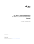
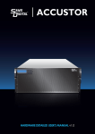
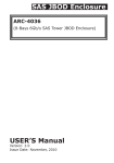
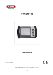
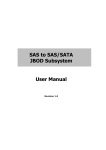
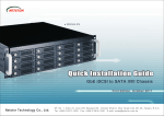
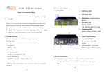
4U 24-Bay
NS385S-8028
5U 48-Bay
NS390S-8028
12Gbps SAS Expander JBOD Enclosure
Version:First Edition
Issue Date:September 2014
SAFETY PRECAUTIONS
Please read this section carefully before proceeding. These precautions
explain the correct and safe use of this device, thereby helping to prevent
injury to you or others, and also help you to minimize the risk of
damaging the device.
Warnings
Always follow the basic warnings listed here to avoid the risk of serious
injury or death from electrical shock, short-circuiting, fire, and other
hazards. These warnings include, but are not limited to:
‧ With the exception of the user-swappable parts, do no attempt to
disassemble or modify the enclosure. If this device appears to be
malfunctioning, contact Netstor Customer Service.
‧ Do not drop the enclosures or any of its drive modules; dropping or
mishandling of the enclosure or drive modules may result in a
malfunction.
‧ Do not insert your fingers or foreign objects inside the enclosure; take
particular care when small children are present.
‧ Do not expose the device to rain, use it near water or containers that
contain liquids which might spill into any openings, or in damp or wet
conditions.
‧ If unusual smells, sounds, or smoke come from the device, or if liquids
enter it, switch it off immediately and unplug it from the electrical
outlet.
‧ Follow the instructions in this manual carefully; contact Netstor
Customer Service for additional advice not covered in this User’s
Guide.
Table of contents
1. Introduction
1.1 Overview…………………………………………………….. P2
1.2 Package Checklist……………………………..…………. P2
2. Hardware Installation
2.1 Panel Layout……………………………………………….. P4
2.2 System Setup……….………………....….…………….…
2.2.1 Host Setup……….…….………….……………..…
2.2.2 Enclosure Setup………………………………………..
2.2.2.1 Getting Started……………………………………..
P8
P8
P8
P8
2.2.2.2 HDD Installation…………………..………………. P8
2.2.2.3 Connection between SAS Expander enclosure
and host………………………………..…………… P10
2.2.2.4 RAID Setup……………………..….…………… P14
2.2.2.5 Add more SAS Expander enclosures……..…. P14
3. LCD Configuration Manager
3.1 Using Touch-Control Keypad……………….….……… P17
3.2 Navigation Map of the LCD…………………………… P18
4. CLI Manager
4.1 RS-232C Port Pin Assignment…………………...…….. P22
4.2 Start-up VT100 Screen…………………………...……… P23
4.3 CLI Command……………………………..…………..….. P28
5. Q&A……………………………………...…...………... P36
Netstor
|
1
1. Introduction
1.1 Overview
Netstor’s enterprise-class 12Gbps SAS Expander JBOD enclosures are
designed to provide storage expansion for 12G/6Gbps SAS RAID card.
The enclosure is equipped with 12Gbps SAS Expander supporting
high-reliable SAS 12G/6G/3Gbps or high-capacity SATA 6G/3Gbps HDDs
via single or dual SFF-8644 HD mini-SAS cable host connectivity.
Through the extra HD mini-SAS ports, expansion to more 12Gbps SAS
Expander enclosures is available, ensuring it the most cost-effective
storage expansion.
1.2 Package Checklist
Before the installation of the enclosure, verify the items below are
included in the package.
□ NS385S-8028
A.
Enclosure × 1
B.
HDD tray (installed in the NS385S-8028) × 24
C.
Power cord × 2
D.
CD containing user’s manual × 1
E.
HDD mounting screw × 96
F.
Key for HDD tray × 2
G.
HD mini-SAS (SFF-8644) to HD mini-SAS (SFF-8644) data cable
(optional) × 1
2
|
Netstor
□ NS390S-8028
A. Enclosure × 1
B. HDD tray (installed in the NS390S-8028) × 48
C. Power cord × 2
D. CD containing user’s manual × 1
E. HDD mounting screw × 192
F. Key for HDD tray × 2
G. HD mini-SAS (SFF-8644) to HD mini-SAS (SFF-8644) data cable
(optional) × 2
If any of the items listed above is missing or damaged, please contact the
sales representative.
Netstor
|
3
2. Hardware Installation
This section gives the layout of enclosure’s panel and describes the
procedures for setting up the SAS Expander enclosure.
2.1 Panel Layout
□ NS385S-8028
Front panel
1. Drive presence LED
White – Power On
2. Activity indicator LED
Blue – HDD ready
Flash blue – Access
Flash pink – Rebuilding
Red – HDD failure
Rear panel
3.
Power switch button
4.
Power cord receptacle
5.
LCD display – see Chapter 3 on page 11 for LCD configuration
6.
Enclosure power LED
Green – Power On
7.
Busy LED
Flash green – Host computer accessing the enclosure
8.
Fault LED
Unlit – Enclosure normal
Red – Enclosure failure
9.
4
Link LED
|
Netstor
There are three SAS ports, CH2, CH1, CH0, on SAS Expander. Each
SAS port includes four links; each link has 12Gbps bandwidth
maximum.
(1) When green link LED is lit for 4 seconds, it indicates four links
have connected for 48Gbps.
(2) When green link LED is lit for 2 seconds and light off for 2
seconds, it indicates two links have connected for 24Gbps.
(3) When green link LED is lit for 1 second and light off for 3 seconds,
it indicates only one link is connected for 12Gbps.
10. Activity LED
Blue – When activity LED illuminates, it indicates SAS host accesses
to NS385S-8028.
11. SAS Exp. out connector (SAS CH2)
12. SAS Exp. in connector (SAS CH1)
13. SAS Exp. out connector (SAS CH0)
14. RJ-45 LAN connector – reserved for future function upgrade
15. RJ-11 for CLI configuration
16. Fan 1
17. Fan 2
18. Fan 3
19. Fan 4
20. Fan 5
Netstor
|
5
□ NS390S-8028
Front panel
1. Power On/Off Button
2. LCD display one
3. LCD display two
– see Chapter 3 on page 11 for LCD configuration
4. Enclosure power LED
Green – Power On
5. Busy LED
Flash green – Host computer accessing the enclosure
6. Fault LED
Unlit – Enclosure normal
Red – Enclosure failure
7. Drive presence LED
White – Power On
8. Activity indicator LED
Blue – HDD ready
Flash blue – Access
Flash pink – Rebuilding
Red – HDD failure
Rear panel
9. Power switch button
10. Power cord receptacle
11. SAS Exp. out connector (SAS CH2)
12. SAS Exp. in connector (SAS CH1)
13. SAS Exp. out connector (SAS CH0)
6
|
Netstor
14. Activity LED
Blue – When activity LED illuminates, it indicates SAS host accesses
to NS390S-8028.
15. Link LED
There are three SAS ports, CH2, CH1, CH0, on SAS Expander. Each
SAS port includes four links; each link has 12Gbps bandwidth
maximum.
(1) When green link LED is lit for 4 seconds, it indicates four links
have connected for 48Gbps.
(2) When green link LED is lit for 2 seconds and light off for 2 seconds,
it indicates two links have connected for 24Gbps.
(3) When green link LED is lit for 1 second and light off for 3 seconds,
it indicates only one link is connected for 12Gbps.
16. RJ-45 LAN connector – reserved for future function upgrade
17. RJ-11 for CLI configuration
18. Fan 1
19. Fan 2
20. Fan 3
21. Fan 4
22. Fan 5
23. Fan 6
24. Fan 7
25. Fan 8
Netstor
|
7
2.2 System Setup
The section of system setup includes host part and enclosure part.
Settings to both parts need to be done for configuration.
2.2.1
Host Setup
The host must have a 12G/6Gbps SAS RAID card for connection with SAS
Expander enclosure. The driver of RAID card needs to be installed on
operating system to allow RAID card work with enclosure.
2.2.2
Enclosure Setup
Detailed procedures on setting up SAS Expander enclosure are provided
in the following sub-sections.
2.2.2.1 Getting Started
Remove SAS Expander enclosure from its packaging. Arrange the
enclosure near host PC, server, or workstation.
2.2.2.2 HDD Installation
1. The HDD tray can be pulled out directly if drive trays are in front. If
drive trays are built on top side, remove the top cover by loosening
the two thumbscrews in front for accessing the drive tray.
8
|
Netstor
2. Hold one of the HDD trays from the enclosure. Push its button
leftward for releasing the lever until the lever pops out.
3. Place the drive tray on a flat surface. Attach the HDD into tray.
The heads of the four screws must be level with the drive tray when
the HDD is attached to it. Otherwise, a screw can take hold of the tray
from the side and prevent the tray to be pulled out of the array.
4. Adopt four of the screws provided, and fasten the HDD on tray.
Tighten each screw to fasten the drive snugly to tray. Do not overly
tighten the screws.
Do not force the lever to close when inserting the drive tray into
enclosure. If a lever does not close smoothly, draw out, insert the
drive tray again, and press the lever to close.
Netstor
|
9
5.
Insert the drive tray into enclosure correctly until its lever appears
to shut, and press the lever to close until it clicks to ensure drive
tray is properly installed in enclosure.
6.
Repeat steps 2 to 5 for further drives.
2.2.2.3 Connection between SAS Expander enclosure and host
NS385S-8028
Connect SAS Expander enclosure to the host through data cable.
Diagram for connection between enclosure and host is shown below:
10 |
Netstor
NS390S-8028
Recommended connection:
RAID card with two external ports connecting SAS Expander
enclosure for faster speed connection.
1.
At rear of SAS Expander enclosure, there are two SAS Expanders
numbered 1 and 2 from right to left. SAS Expander 1 is the first
SAS Expander inside the enclosure and SAS Expander 2 is the
second.
2.
Connect one end of data cable to the first port on RAID card at
host side, and connect the other end of data cable to SAS Exp. In
connector (SAS CH1) on SAS Expander 1.
Netstor
|
11
3.
Connect one end of data cable to the second port on RAID card at
host side, and connect the other end of data cable to SAS Exp. In
connector (SAS CH1) on SAS Expander 2.
Optional connection:
RAID card with only one external port connecting SAS Expander
12 |
Netstor
1.
At rear of SAS Expander enclosure, there are two SAS Expanders
numbered 1 and 2 from right to left. SAS Expander 1 is the first
SAS Expander inside the enclosure and SAS Expander 2 is the
second.
2.
Connect one end of data cable to RAID card at host side, and
connect the other end of data cable to SAS Exp. In connector (SAS
CH1) on SAS Expander 1.
3.
Connect one end of data cable to the left SAS Exp. Out connector
(SAS CH2) on SAS Expander 1, and connect the other end of data
cable to SAS Exp. In connector (SAS CH1) on SAS Expander 2.
Netstor
|
13
2.2.2.4 RAID Setup
To set up RAID volume on enclosure, users need to set volume from
GUI interface of RAID card. Refer to RAID card’s user guide for RAID
configuration.
2.2.2.5 Add more SAS Expander enclosures
Users can add more enclosures according to their demands for storage.
The SAS Expander enclosure can run in one of the following two
modes:
1. Normal Mode (default)
2. Zone Mode
Either mode must be selected using CLI utility – see Chapter 4 on page
15 for CLI configuration. The manufacturer’s default is at Normal Mode.
Change the mode when SAS Expander enclosure is powered on. The
change will not take effect until SAS Expander enclosure is rebooted.
To access the cascaded SAS Expander enclosures through one host,
the user only needs to use the default Normal Mode.
To allow two hosts with each computer installed with a RAID card to
share the same cascaded SAS Expander enclosures, the enclosure
needs to be set as Zone Mode.
14 |
Netstor
1. Normal Mode
The host can communicate with all the drives in the cascaded SAS
Expander enclosures. The number of HDDs the cascaded enclosures
can support depends on RAID card’s firmware. The following figure
shows the connection between host and cascaded SAS Expander
enclosures.
2. Zone Mode
The following figure shows SAS Expander enclosure that is split into
two virtual groups. Each group’s drive channel is controlled by
individual host’s RAID card using SAS CH1 and SAS CH2. Refer to
section 4.3 CLI Command for gr command.
Netstor
|
15
For enclosure monitoring and configuration, users can choose either
LCD or CLI.
LCD includes functions covering fan, temperature, voltage
monitoring, HDD link speed, and enclosure alarm. Refer Chapter 3
for LCD configuration.
For CLI, besides having all LCD’s functions, it also includes system
information, event log, firmware update, and configuration of
3. LCD Configuration Manager
The SAS Expander enclosure’s LCD is a character-based utility that can
be used after the unit is powered on. Use LCD configuration utility to
monitor and configure:
• Alerts Menu
• Voltage
• Set Link
• Set Alarm
• Set Password
• Save Config
• System Reset
The LCD function keys are the primary user interface for SAS Expander
enclosure. Except for the “Firmware update”, all configurations can be
made through the interface.
16 |
Netstor
3.1 Using Touch-Control Keypad
The keypad and LCD is the primary user interface for the SAS Expander
enclosure. All configurations, enclosure management and its properly
connected disk arrays can be performed via the interface. The keypad
and LCD are connected to the SAS Expander enclosure to access the
built-in configuration that resides in the firmware of SAS Expander.
The LCD provides info that includes menu and status information. The
LCD screen shows up to two lines at a time of menu items or other
information.
The initial screen is shown as follows:
Function Key Definitions:
The four function keys to the right of LCD perform the following functions:
Netstor
|
17
There are a variety of failure conditions that cause SAS Expander
enclosure’s monitoring LED to light. The table below provides a summary
of the LED to the top of keypad.
3.2 Navigation Map of the LCD
The password function allows user to set SAS Expander enclosure’s
password for protection. Once the password is set, the user can only
monitor and configure SAS Expander enclosure by providing the correct
password. The default password for the enclosure is 0000.
The following flow is an expansion of LCD setup item hierarchical menu.
18 |
Netstor
• Alerts Menu
Show which device that fails to work, its sub-items could be "Power
Supply", "Fan", "Temp. Sensor" and "Voltage Sensor".
• Voltage
Show enclosure chip voltage in status data, represent in V.
The sub-items are shown below:
Netstor
|
19
1.2V- , the expander voltage is 1.2V
5V- , the expander voltage is 5V
For the setup item, the LCD key represents:
Up key to enter the 0 - 9 data.
Down key to enter "a" - "z" and "A" - "Z" data.
Enter key to confirm the input or ready to update a sub-item data.
Esc/Exit key to go back to the main selection.
• Set Link
Set HDD devices maximun/minimun link speed rate. The value could be
12G, 6.0G, 3.0G or 1.5G. Each HDD device link speed will have the
sub-item as shown below:
_Set Max. Rate
12.0G
_Set Min. Rate
1.5G
• Set Alarm
Set enclosure buzzer warning/critical error beep style or mute the current
beep. The value could be "Sound 1", "Sound 2", "Sound 3", "Sound 4"
and "Sound Disabled". Sound 1 to 4 means different frequency sound.
Sound disabled means disable the
sound beep. The sub-items are shown below:
_Set Alarm Beep
Mute beep
20 |
Netstor
_Warning Alarm
Sound 2
_Critical Alarm
Sound 3
• Set Password
Change the enclosure LCD password. The sub-item is
"Set New PWD".
• Save Config
Save all the updated option value into non-volatile memory area.
• System Reset
Reboot the system.
4. CLI Manager
This Command Line Interface (CLI) is provided to manage SAS Expander
enclosure’s functions. The CLI is useful in environments where a GUI
interface is not available.
• Locations of RS-232C Port
The SAS Expander enclosure uses the RJ-11 port as the serial port
interface. Use the cable included in the box to configure SAS Expander
controller.
Netstor
|
21
• Establishing the Connection for the RS-232 Port
The CLI function can be managed by using an ANSI/VT-100 compatible
terminal emulation program. The appropriate installation procedure
needs to be completed before proceeding to the CLI function. Whichever
terminal emulation program is used, it must support the 1K XMODEM file
transfer protocol.
The serial port on SAS Expander enclosure’s I/O shield can be used in
VT100 mode. The provided interface cable converts the RS232 signal of
the RJ-11 connector on enclosure into a 9-pin D-Sub male connector. A
VT-100 compatible terminal or a PC running a VT-100 terminal emulation
program to the serial port can access the text-based setup menu.
4.1 RS-232C Port Pin Assignment
To ensure proper communication between SAS Expander enclosure and
VT-100 Terminal Emulation, configure the VT100 terminal emulation
settings to the values below:
22 |
Netstor
The controller RJ-11 connector pin assignments are defined as below.
4.2 Start-up VT100 Screen
By connecting a VT100 compatible terminal, or a PC operating in an
equivalent terminal emulation mode, all CLI administration functions can
be exercised from the VT100 terminal.
There are a wide variety of Terminal Emulation packages, but for the
most part they should be very similar. The following procedure is an
example of setting up VT100 Terminal in Windows XP using
HyperTerminal version 3.0 or higher. For Windows 7 or above, the
HyperTerminal needs to be downloaded; here is the reference site:
http://en.softonic.com/s/hyperterminal-windows-7
Netstor
|
23
Step 1. Open the “Taskbar Start”/”Programs"/"Accessories"/"Com
mmunications"/"HyperTerminal". (HyperTerminal requires version
3.0 or higher).
Step 2. Open “HYPERTRM.EXE”.
24 |
Netstor
Step 3. Enter a name you prefer and then click “OK”.
Step 4. Select an appropriate connecting port and then click "OK".
Step 5. Configure the port parameter settings and then click “OK”.
Bits per second: 115200
Data bits: 8
Parity: None
Stop bits: 1
Flow control: None
Netstor
|
25
Step 6. Open the file menu and select “Properties”.
Step 7. Configure the "Connect To" setting.
26 |
Netstor
Step 8. Configure the "Settings" items and then click "OK".
Function, arrow and ctrl keys act as: Terminal Keys
Backspace key sends: Crtl+H
Emulation: VT100
Telnet terminal: VT100
Back scroll buffer lines: 500
Netstor
|
27
4.3
CLI Command
This section provides detailed information on CLI function of SAS
Expander enclosure. Type in lower case for all commands.
The following table gives a summary of all commands to CLI function.
Function
Set password for SAS
Expander enclosure
Show system info on
enclosure
Show status of each
component on enclosure
Save system setting
Set temperature warning
limit
Set fan speed
Set buzzer's sound level of
enclosure
Set the link rate of HDD in
enclosure
Command
Syntax
pass
pass [enter]
sys
sys [enter]
lsd
lsd [ hdd | temp | volt | con ]
st
st [enter]
th
fan
bu
link
th [ID No.] [High warn value]
[low warn value]
fan [lowest speed value]
[warning speed value]
bu [warning beep value]
[critical beep value]
link [Slot No.] [max link
speed] [min link speed]
Enable DataBolt™
performance for 6G/3G
dhpm
dhpm [on or off]
HDD
Staggering HDD spin-up
Show event log of SAS
Expander enclosure
28 |
Netstor
spin
showlogs
spin [delay value] [drive
number]
showlogs [enter]
Update the firmware of
SAS Expander enclosure
Set zone group
Show all phy counters
Reset all phy counters
Show SAS address of
enclosure
Show list of commands
Exit CLI of SAS Expander
enclosure
fdl
gr
counters
counters
reset
fdl [ code | mfgb ]
gr [Group No.] [Cable No.]
[range of slots]
counters [enter]
counters reset [enter]
sasaddr
sasaddr [enter]
help
help [enter]
lo
lo [enter]
1. pass
The default password for SAS Expander enclosure is 0000. The user can
set new password for the enclosure.
Syntax: pass [enter]
CLI>pass
Old Password: ****
New Password: ****
Verify New Password: ****
CLI>st
2. sys
Show system information on enclosure. The information includes vendor
name, model name, serial number, expander port number, product
revision, chip name, customer code, manufacturer data revision, and
working time.
Netstor
|
29
Syntax: sys [enter]
CLI>sys
3. lsd
Show status of each component on enclosure. The component includes
HDD, temperature, voltage, and connector.
Syntax: lsd [ hdd | temp | volt | con ]
To show status of HDD:
CLI>lsd hdd
To show status of enclosure and chip temperature:
CLI>lsd temp
To show status of SAS Expander’s voltage
CLI>lsd volt
To show status of enclosure’s three external HD mini-SAS connectors:
CLI>lsd con
4. st
Save system setting. Every time after parameter is entered into CLI, the
user needs to save the parameter to take effect.
Syntax: st [enter]
CLI>st
30 |
Netstor
5. th
Set warning beep for highest and lowest temperature for enclosure, SAS
Expander chip, and HDD.
Syntax: th [ID No.] [High warning value] [low warning value]
Firstly, determine the ID number of enclosure, chip, or HDD that will be
set for warning temperature.
CLI>th
To set temperature warning beep for enclosure:
CLI>th [ID number of enclosure] [high warning value in degrees
Celsius] [low warning value in degrees Celsius]
CLI>st
To set temperature warning beep for SAS Expander chip:
CLI>th [ID number of chip] [high warning value in degrees Celsius]
[low warning value in degrees Celsius]
CLI>st
To set temperature warning beep for individual HDD:
CLI>th [ID number of HDD] [high warning value in degrees Celsius]
[low warning value in degrees Celsius]
CLI>st
6. fan
Set speed of enclosure’s four fans.
Command: fan
Syntax: fan [lowest speed value] [warning speed value]
Speed value ranges from 1 ~ 7.
1 is the lowest speed. 7 is the highest speed.
Netstor
|
31
CLI>fan [lowest speed value] [warning speed value]
CLI>st
7. bu
Set enclosure’s buzzer sound level.
Command: bu
Syntax: bu [warning beep value] [critical beep value]
Beep value ranges from 0 ~ 3.
0 means no sound. 3 is the loudest sound.
CLI>bu [warning beep value] [critical beep value]
CLI>st
If SAS expander’s buzzer beeps due to fan failure or over-temperature,
and the user wants to mute it temporarily, the following command can be
applied:
CLI>bu mute
8. link
Set the link rate of HDD in enclosure.
Command: link
Syntax: link [Slot No.] [max link speed] [min link speed]
Link speed value ranges from 9 ~ 11.
9 means 3Gbps, 10 means 6Gbps, and 11 means 12Gbps.
CLI>link [Slot No.] [9~11] [9~11]
CLI>st
Reboot enclosure to take effect.
32 |
Netstor
9. dhpm
Enable DataBolt™ performance for 6G/3Gbps HDDs. The DataBolt™
function is disabled by default. When DataBolt™ is enabled, though the
throughput will be reinforced, the IOPS performance will be affected.
Command: dhpm
Syntax: dhpm [on or off]
CLI>dhpm on
CLI>st
Reboot enclosure to take effect.
10.spin
Staggering HDD spin-up
Command: spin
Syntax: spin [delay value] [drive number]
Delay value can be 512 ms or 1024 ms.
CLI>spin [512 or 1024] [drive number]
CLI>st
11.showlogs
Show event log of enclosure
Command: showlogs
Syntax: showlogs [enter]
CLI>showlogs
12. fdl
Update the firmware of enclosure
Command: fdl
Syntax: fdl [code | mfgb]
To update SAS Expander firmware:
Netstor
|
33
CLI>fdl code
To update SAS Expander data file:
CLI>fdl mfgb
13. gr
Set zone group
Command: gr
Syntax: gr [Group number] [Cable number] [range of HDD slots]
dev 1 means group 1; dev 2 means group 2.
c0 means cable0, c1 means cable1, c2 means cable2.
cable0: CH0, cable1: CH1, cable2: CH2.
CLI>gr dev 1 c0 1 6
CLI>gr dev 2 c1, c2 7 16
CLI>st
Reboot enclosure to take effect.
14.counters
Show all phy counters
Command: counters
Syntax: counters reset [enter]
CLI>counters
34 |
Netstor
15.Counters reset
Reset all phy counters
Command: counters reset
Syntax: counters reset [enter]
CLI>counters reset
16. sasaddr
Show SAS address of enclosure
Command: sasaddr
Syntax: sasaddr [enter]
CLI>sasaddr
17. help
Show list of commands
Command: help
Syntax: help [enter]
CLI>help
18.lo
Exit CLI of SAS Expander enclosure
Command: lo
Syntax: lo [enter]
CLI>lo
Netstor
|
35
5. Q&A
Question 1:
When one of the fans breaks down, the buzzer inside the SAS Expander
enclosure will beep to alert the administrator; how to mute the beep?
Answer:
Select “Set Alarm” from the LCD display, enter password “0000” (default),
select “Mute Beep”, and press enter to mute. The other way to mute the
beep is to click the mute button from the GUI interface of RAID card.
Question 2:
When one of the PSU units breaks down, power supply’s buzzer will beep
to alert the administrator; how to mute the beep?
Answer:
Press the green alarm mute button on PSU at rear of SAS Expander
enclosure.
36 |
Netstor
Note
Contacting Netstor Customer Service
The Netstor website at www.netstor.com.tw has technical updates, and
the most current product and support information. Please check our
website for the latest updates and online support files for helpful
information. If further assistance is needed, please contact us in one of
the following ways:
Skype: netstor_fae
E-mail: [email protected]
Tel: +886-2-2917-1500