1
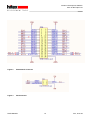
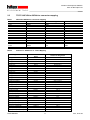
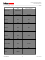
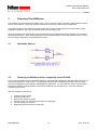
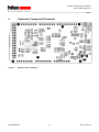
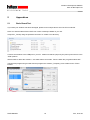
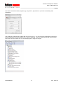
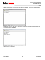
Aurduino Hardware User Manual
Basic information on the AURduino development board
Connectors, board layout, component placement, power options
PRELIMINARY
Hardware User Manual!
4269.40100, V0.4, 2015-02
Har dw are Ma nual
Aurduino Development Platform
Aurix 32-Bit Triple Core
CONFIDENTIAL
Edition 2015-02
Published by:
Hitex (U.K.) Limited.
University Of Warwick Science Park, Coventry, CV4 7EZ, UK
© 2015 Hitex (U.K.) Limited.
All Rights Reserved.
Legal Disclaimer
The information given in this document shall in no event be regarded as a guarantee of conditions or
characteristics. With respect to any examples or hints given herein, any typical values stated herein and/or any
information regarding the application of the product, Hitex (UK) Ltd. hereby disclaims any and all warranties and
liabilities of any kind, including without limitation, warranties of non-infringement of intellectual property rights of
any third party.
Information
For further information on technology, delivery terms and conditions and prices, please contact the nearest
Hitex Office (www.hitex.co.uk).
Aurduino Development Platform
Aurix 32-Bit Triple Core
CONFIDENTIAL
Document Change History
Date
Version
Changed By
Change Description
8/8/2014
0.1
M Beach
First version
M Beach
Revised top view
9/8/2014
0.2
20/2/2015
0.3
M Beach/D Greenhill
Revised for Rev B HW
9/4/2015
0.4
M Beach
Added board test
We Listen to Your Comments
Is there any information in this document that you feel is wrong, unclear or missing?
Your feedback will help us to continuously improve the quality of this document.
Please send your comments (including a reference to this document) to:
[email protected]
PRELIMINARY
3
V0.4, 2015-02
Aurduino Development Platform
Aurix 32-Bit Triple Core
CONFIDENTIAL
Table of Contents
1
1.1
1.2
1.3
Release Notes HW Revision B .......................................................................................................... 7
AURduino RevB Known Problems ....................................................................................................... 7
CIC61508 (Safety version only) ........................................................................................................... 7
VIN Pin ................................................................................................................................................. 7
2
2.1
2.2
2.3
Arduino-Based Connector Details.................................................................................................... 8
Board Layout ........................................................................................................................................ 8
Connector Pin Allocation ...................................................................................................................... 9
TC275 ASCLIN to AURduino connector mapping ............................................................................. 11
3
3.1
3.2
Powering The AURduino ................................................................................................................. 13
Selectable Options ............................................................................................................................. 13
Restoring an AURduino with a completely erased FLASH. ............................................................... 13
4
Underside Component Placement.................................................................................................. 14
5
5.1
Appendices ....................................................................................................................................... 16
Basic Board Test ................................................................................................................................ 16
PRELIMINARY
4
V0.4, 2015-02
Aurduino Development Platform
Aurix 32-Bit Triple Core
CONFIDENTIAL
List of Figures
Figure 1
Figure 2
Figure 3
Figure 4
Top view of Aurduino ........................................................................................................................... 8
Extended IO Connector ...................................................................................................................... 10
SPI Connector .................................................................................................................................... 10
Bottom view of Aurduino .................................................................................................................... 14
PRELIMINARY
5
V0.4, 2015-02
Aurduino Development Platform
Aurix 32-Bit Triple Core
CONFIDENTIAL
List of Tables
Table 1
Table 2
ASCLIN to AURduino connector mapping ......................................................................................... 11
Arduino To AURduino To TC275 Mapping ........................................................................................ 11
PRELIMINARY
6
V0.4, 2015-02
Aurduino Development Platform
Aurix 32-Bit Triple Core
CONFIDENTIAL
1 Release Notes HW Revision B
1.1
AURduino RevB Known Problems
The Aurduino Revision B has a number of functional characteristics, listed below.
1. It will only run at 5V. It is possible to get 3V3 operation but this requires the changing of a voltage
regulator and the changing of some resistors
1.2
CIC61508 (Safety version only)
The CIC61508 is programmed with the VANIA3.2 firmware release.
1.3
VIN Pin
The VIN pin on the AURduino power connector strip allows access to the 9-12V input from the power jack
socket. This may be used to power shields that require a higher voltage e.g. the DC motor shield. In this case,
please note that the maximum continuous current that can be drawn through this pin is 1.5A due to the 0.5mm
track used..
PRELIMINARY
7
V0.4, 2015-02
Aurduino Development Platform
Aurix 32-Bit Triple Core
CONFIDENTIAL
2
Arduino-Based Connector Details
The Aurduino is based on the Arduino Due (SAM3X) form factor. Where possible, the pin functionality of the
Due has been implemented using an equivalent Aurix peripheral.
2.1
Board Layout
PWMH
D17
PWML
D8
D7
A0
POWER
Figure 1
COMMUNICATION
D0
A5
ADCL
A11
ADCH
Top view of Aurduino
PRELIMINARY
8
V0.4, 2015-02
Aurduino Development Platform
Aurix 32-Bit Triple Core
CONFIDENTIAL
2.2
Connector Pin Allocation
PRELIMINARY
9
V0.4, 2015-02
Aurduino Development Platform
Aurix 32-Bit Triple Core
CONFIDENTIAL
Figure 2
Extended IO Connector
Figure 3
SPI Connector
PRELIMINARY
10
V0.4, 2015-02
Aurduino Development Platform
Aurix 32-Bit Triple Core
CONFIDENTIAL
2.3
TC275 ASCLIN to AURduino connector mapping
Table 1
ASCLIN to AURduino connector mapping
TC275 Port Pin
ASCLIN
Board Marking
P15.0
ASC1
TX0
P15.1
ASC1
RX0
Comment
Serial0
P33.9
P33.8
ASC2
ASC2
TX1
RX1
Serial1
P20.0
P20.3
ASC3
ASC3
TX2
RX2
Serial2
P15.2
P15.3
ASC0
ASC0
TX
RX
Serial
P15.7
P32.2
ASC3
ASC3
TX
RX
Table 2
SerialASC - Available via
USB
Arduino To AURduino To TC275 Mapping
Arduino Signal Name
Analog pin 0
Analog pin 1
Analog pin 2
Analog pin 3
Analog pin 4
Analog pin 5
Analog pin 6
Analog pin 7
Analog pin 8
Analog pin 9
Analog pin 10
Analog pin 11
Analog pin 12/DAC0
Analog pin 13/DAC1
Analog pin 14/CAN RX
Analog pin 15/CAN TX
Digital pin 4 (PWM/SS)
Analog Reference AREF
Digital pin 0 (RX0)
Digital pin 1 (TX0)
Digital pin 2 (PWM)
Digital pin 3 (PWM)
Digital pin 5 (PWM)
Digital pin 6 (PWM)
Digital pin 7 (PWM)
Digital pin 8 (PWM)
Digital pin 9 (PWM)
Digital pin 10 (PWM/SS)
Digital pin 11 (PWM/MOSI)
Digital pin 12 (PWM/MISO)
PRELIMINARY
AURduino Connector
Name
TC275T Pin Assignment
ADCL.1
ADCL.2
ADCL.3
ADCL.4
ADCL.5
ADCL.6
ADCL.7
ADCL.8
ADCH.1
ADCH.2
ADCH.3
ADCH.4
ADCH.5
ADCH.6
ADCH.7
ADCH.8
PWML.5
PWMH.8
PWML.1
PWML.2
PWML.3
PWML.4
PWML.6
PWML.7
PWML.8
PWMH.1
PWMH.2
PWMH.3
PWMH.4
PWMH.5
SAR4.7
SAR4.6
SAR4.5
SAR4.4
SAR3.0/P10.7
SAR3.1/P10.8
SAR2.5
SAR2.4
SAR0.3
SAR0.2
SAR0.1
SAR0.0
SAR5.4/P20.9/P33.10
SAR5.5/P33.11
SAR5.6/P20.7 CAN0 RX
SAR5.7/P20.8 CAN0 TX
P10.4
AREF
P15.3
P15.2
P2.0
P2.1
P2.3
P2.4
P2.5
P2.6
P2.7
P10.5
P10.3
P10.1
11
V0.4, 2015-02
Aurduino Development Platform
Aurix 32-Bit Triple Core
CONFIDENTIAL
Arduino Signal Name
Digital pin 13 (PWM/SPCK)
Digital pin 14 (TX3)
Digital pin 15 (RX3)
Digital pin 16 (TX2)
Digital pin 17 (RX2)
Digital pin 18 (TX1)
Digital pin 19 (RX1)
Digital pin 20 (SDA)
Digital pin 21 (SCL)
Digital pin 22
Digital pin 23
Digital pin 24
Digital pin 25
Digital pin 26
Digital pin 27
Digital pin 28
Digital pin 29
Digital pin 30
Digital pin 31
Digital pin 32
Digital pin 33
Digital pin 34
Digital pin 35
Digital pin 36
Digital pin 37
Digital pin 38
Digital pin 39
Digital pin 40
Digital pin 41
Digital pin 42
Digital pin 43
Digital pin 44 (PWM)
Digital pin 45 (PWM)
Digital pin 46 (PWM)
Digital pin 47
Digital pin 48
Digital pin 49
Digital pin 50 (MISO)
Digital pin 51 (MOSI)
Digital pin 52 (SCK)
Digital pin 53 (SS)
SPI connector 1
SPI connector 2
SPI connector 3
SPI connector 4
SPI connector 5
SPI connector 6
I2C SDA1
I2C SCL1
GND
PRELIMINARY
AURduino Connector
Name
TC275T Pin Assignment
PWMH.6
COMMUNICATION.8
COMMUNICATION.7
COMMUNICATION.6
COMMUNICATION.5
COMMUNICATION.4
COMMUNICATION.3
COMMUNICATION.2
COMMUNICATION.1
XIO.3
XIO.4
XIO.5
XIO.6
XIO.7
XIO.8
XIO.9
XIO.10
XIO.11
XIO.12
XIO.13
XIO.14
XIO.15
XIO.16
XIO.17
XIO.18
XIO.19
XIO.20
XIO.21
XIO.22
XIO.23
XIO.24
XIO.25
XIO.26
XIO.27
XIO.28
XIO.29
XIO.30
XIO.31
XIO.32
XIO.33
XIO.34
MISO3
+5V
SPCK3
MOSI3
RESET
GND
PWMH.10
PWMH.9
PWMH.7
P10.2
P15.0 ASC1 RX TXCAN2
P15.1 ASC1 RX RXCAN2
P33.9 ASC2 TX
P33.8 ASC2 RX
P20.0 ASC3 TX
P20.3 ASC3 RX
P15.4
P15.5
P14.0
P14.1
P15.6
P00.0
P00.8
P00.1
P00.9
P00.2
P00.10
P00.3
P00.11
P00.4
P00.12
P00.5
P33.2
P00.6
P33.1
P00.7
P33.2
P11.9
P11.10
P11.11
P33.3
P11.2
P11.3
P11.6
P21.3 (B-step) P21.1 (A-step) via link
P21.0
P33.4 + P21.3
P2.8 + P13.3
P33.5 + P15.8
P11.12 + P20.10
P22.1
P22.3
P22.0
P13.1
P13.2
GND
12
V0.4, 2015-02
Aurduino Development Platform
Aurix 32-Bit Triple Core
CONFIDENTIAL
3
Powering The AURduino
The Aurduino can be powered from USB or from 7-12V on the jack socket. The switch S501 allows the power
source to be selected. The jumper position towards the centre of the board selects USB power.
It is possible to power the board from just the USB however some shields require more current than can be
supplied via USB so in the case, the external power jack should be used.
When powered from the external jack, the CIC61508 has its own independent power regulator, as required by
the safety architecture. When using USB power, the CIC61508 shares is power supply with the Aurix. This is
the non-safety configuration, for development use only.
3.1
Selectable Options
3.2
Restoring an AURduino with a completely erased FLASH.
If the TC275 PFLASH becomes completely erased or if the bootmode headers are damaged, the device can no
longer be accessed via JTAG or DAP. The debugger will report “No Valid ABM On Target” and the FLASH
cannot be programmed, even though it might appear to have been. To overcome this, JP201 can be used to
temporarily enable the debug interface so that the PFLASH can be reprogrammed. To do this, follow the
procedure given below:
With the AURduino powered up:
1.
2.
3.
4.
5.
6.
Close the jumper JP201
Press the reset button
Remove the jumper on JP201
Attempt to start your Flash programming tool or debugger
The tool should now connect
Reprogram the PFLASH in the usual way
PRELIMINARY
13
V0.4, 2015-02
Aurduino Development Platform
Aurix 32-Bit Triple Core
CONFIDENTIAL
4
Underside Component Placement
Figure 4
Bottom view of Aurduino
PRELIMINARY
14
V0.4, 2015-02
Aurduino Development Platform
Aurix 32-Bit Triple Core
CONFIDENTIAL
PRELIMINARY
15
V0.4, 2015-02
Aurduino Development Platform
Aurix 32-Bit Triple Core
CONFIDENTIAL
5
Appendices
5.1
Basic Board Test
If you think your Aurduino has been damaged, please run this simple test to see if the CPU is still OK.
Note: It is assumed that Infineon DAS v4.6 or later is already installed on your PC.
Unzip EOL_Test.zip using the password “aurduino” to create a new directory:
Connect the Aurduino to the USB port on your PC. Make sure that the jumper by the power jack socket is in the
“USB” position.
Wait for DAS to detect the Aurduino – this takes about 15 seconds. Run the batch file “programAurduino.bat”.
The Memtool programming tool will start and program the Aurduino_Template_5.hex hexfile into the TC275
FLASH.
PRELIMINARY
16
V0.4, 2015-02
Aurduino Development Platform
Aurix 32-Bit Triple Core
CONFIDENTIAL
Now start a terminal emulation program (e.g. putty, MTTY, Hyperterm etc.) and use the following serial
parameters:
The COM port created by the Aurduino will vary from PC to PC. You can find it in the Windows Control Panel Device Manager under Ports (COM & LPT). Here it is COM196. Note it is usually the second virtual comport
that is the active one. Make sure your terminal program is using this comport!
PRELIMINARY
17
V0.4, 2015-02
Aurduino Development Platform
Aurix 32-Bit Triple Core
CONFIDENTIAL
With the terminal program running, press the reset button on the Aurduino. The following text should appear:
Now press any alpha key – here it was ‘A’. The key you pressed will be printed into the terminal and the LED
on the Aurduino should start to flash.
That completes a successful test.
PRELIMINARY
18
V0.4, 2015-02
Aurduino Development Platform
Aurix 32-Bit Triple Core
CONFIDENTIAL
PRELIMINARY
19
V0.4, 2015-02
www.hitex.co.uk
Published by Hitex (U.K.) Limited.
4269.40100, V0.4