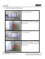
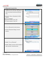
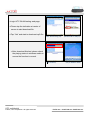
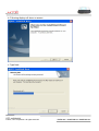
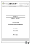
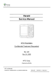
1
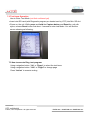
Service Manual
PDA Phone Product
Prodigy
HTC Proprietary
Confidential Treatment Requested
Rev. XA
August 13, 2005
HTC Corp.
Engineering Mobility
HTC confidential
© 2001, HTC Corporation. All rights reserved.
TOTAL 84
CONT.ON. 2 PAGE NO. 1
TITLE: Service Manual for Prodigy
REV.
NO.
DATE
CONTENTS
DEP.
REVISED
XA
Aug 13, 2005
Formal release
GSD
Technical
Support
Johnson Yang
APP´D
STGE.PER.
HTC confidential
© 2001, HTC Corporation. All rights reserved.
TOTAL 84
CONT.ON. 3 PAGE NO. 2
Table of contents
1. INTRODUCTION ·······································································································5
2. PRODUCT SPECIFICATIONS ·····················································································5
2.1 PRODUCT CONFIGURATION ···············································································5
2.2 SPECIFICATIONS OF PRODIGY ··········································································· 6
3. LABELING ············································································································· 10
3.1 MAIN UNIT REGULATORY LABEL ······································································· 10
3.2 SERIAL NUMBER DESCRIPTION ········································································ 10
4. SERVICING TOOLS ································································································ 11
5. ASSEMBLING AND DISASSEMBLING ········································································ 12
5.1 DISASSEMBLING ····························································································· 12
5.2 ASSEMBLING ··································································································26
5.3 NOTIFICATION ONCE BACKUP BATTERY, M//B REPLACEMENT ···························· 36
6. EQUIPMENT OF PROBLEM DIAGNOSTICS ································································ 37
6.1 LIST OF TEST JIGS ··························································································37
6.2 H/W REQUIREMENT FOR PC ··········································································· 37
6.3 SOFTWARE REQUIREMENT ·············································································37
7. DIAGNOSTIC PROGRAMS······················································································38
7.1 LIST OF TEST ITEMS ······················································································38
7.2 TEST ITEMS OPERATION ·················································································39
7.3 HOW TO EXECUTE DIAG TEST PROGRAM ························································· 39
8. BATTERY TEST/JUDGEMENT PROCEDURE ······························································ 40
8.1 CERTIFICATION FLOW ····················································································· 40
8.2 CURRENT CONSUMPTION MEASUREMENT ························································· 41
8.3 WHOLE UNIT CHARGE AND DISCHARGE TEST ···················································· 44
8.4 BATTERY PERFORMANCE ON UNIT WITH RUN DOWN PROGRAM ························ 45
9. LCM INSPECTION CRITERIA ··················································································47
10.RF TEST ·············································································································47
10.1 GSM FUNCTION TEST ···················································································47
10.2 H/W REQUIREMENT ·····················································································47
10.3 TEST CONNECTION························································································47
10.4 RF ANTENNA TEST SPEC. ············································································ 48
10.5 BLUETOOTH FUNCTION TEST ········································································ 52
10.6 WLAN FUNCTION TEST ················································································ 56
HTC confidential
© 2001, HTC Corporation. All rights reserved.
TOTAL 84
CONT.ON. 4 PAGE NO. 3
11. FIRMWARE OF OS/ RADIO UPGRADE ···································································· 58
11.1 RUU ········································································································· 58
11.2 UPLOAD FIRMWARE CODE FROM MASTER UNIT TO SD CARD ························ 64
11.3 USE PRE-LOADED SD CARD TO RE-FLASH UNIT ········································· 68
12. CLASSIFICATION OF NON CONFIRMITY ································································· 70
13.TROUBLE SHOOTING AND REPAIR ········································································· 71
14 SPARE PART LIST ································································································· 77
14.1 UNIT SPARE PART LIST ···················································································· 77
14.2 BOARD LEVEL SPARE PART LIST ······································································ 79
15. APPENDIX··········································································································· 80
A. CUSTOMER, RETAILER MISJUDGMENT······························································· 80
B. HOW TO CHECK BACKUP BATTERY····································································· 82
C. HOW TO PERFORM WARM -RESET AND COLD-RESET ········································· 82
D. REMOVE MAIN BATTERY BEFORE TURN OFF UNIT··············································· 82
HTC confidential
© 2001, HTC Corporation. All rights reserved.
TOTAL 84
CONT.ON. 5 PAGE NO. 4
1.Introduction
This manual provides the technical information to support service activities of PDA phone
(Prodigy). This document contains highly confidential information, any or all of this document should not
be revealed to any third party.
2.Product Specifications
2.1 Product Configuration
Standard Package
ITEM
CONTAINS
1
Main Unit
2
Stylus
3
AC Adapter w/ mini –USB plug
4
Stereo wired headset with microphone
5
Carrying Case
6
Car Kit
7
User’s Manual, Quick start guide, Sync., S/W (CD)
8
Battery
9
Travel charger
10
User’s Manual
HTC confidential
© 2001, HTC Corporation. All rights reserved.
TOTAL 84
CONT.ON. 6 PAGE NO. 5
2.2 Specifications of Prodigy
Item
Specification
Soldering status
z
Meet Lead-free requirement
Platform
z
z
Microsoft Windows Pocket PC phone edition
PDA form factor integrated quad-band GSM/EDGE,
Bluetooth, WiFi, 1.3/2 mega-pixel camera, and sliding
QWERTY keyboard
Outside Dimensions
z
58mm(W) x 109mm(H) x 23.7mm (T)
Weight
z
Less than 160 g (Main unit with battery pack)
Battery
z
z
z
z
z
Removable rechargeable Lithium Polymer battery
1250 mAH
Battery Life:
* WMA: 12 hours
* WMV: 8 hours
Talk time: 3.5 ~ 5 hrs
Standby Time: 150 ~ 200 hrs
AC Adapter
z
z
AC input 100 ~ 240 Vac, 50/60 HZ
DC output : 5V / 1A (typical)
GPRS/GSM
module
(Tri-band) z
z
z
z
Quad-Band ( 850/900/1800/1900)MHz
Internal Antenna
Audio codec: AMR, EFR, FR, HR
Supplement services
* Call holding/waiting/ forwarding
* CLI (Call line Identity)
* Display own number
* Network selection
* Cell broadcast
* Multi-party conference call
* Spool Icon
* Network lock
HTC confidential
© 2001, HTC Corporation. All rights reserved.
TOTAL 84
CONT.ON. 7 PAGE NO. 6
EDGE functionality
z
z
z
z
EGPRS Class B,
Multi-slot Class 10
PBCCH
Incremental Redundancy
SIM
z
z
z
z
z
1.8V/3V SIM Operation
SIM Application Tool Kit release 98 class 3
Over the Air (OTA) programming
FDN/AND/SDN
Security PIN 1&2 control
Memory
z
z
ROM: 128MB (for program and users’ storage)
RAM: 64 MB DDR SDRAM
Processor/Chipset
z
TI OMAP 850
LCD Module
z
z
z
64K-color TFT Transflective LCD with white LED back
light
2.8” 240 x 320 dots resolution
Sensitive Touch Screen
z
z
z
z
One Infrared port IrDA SIR
1.8V/3V SIM card
Mini-SD card slot (top)
2.5ψ stereo audio jack
z
External antenna connector
Stylus
z
Lock type mechanism
Keyboard/Button/Switch
z
z
z
z
Five way navigation button
Power button
Volume control button (up & down)
2 phone button, Send (Yes) & End (No)
z
z
z
z
z
z
z
2 AP buttons ( message-left, IE-right)
2 soft keys
Camera shutter button
Voice command/Voice recorder button
Reset Switch
RF button
Sliding QWERTY keyboard with 39 keys + 2 soft keys
Interface
HTC confidential
© 2001, HTC Corporation. All rights reserved.
TOTAL 84
CONT.ON. 8 PAGE NO. 7
Notification
z
z
z
One Bi-color LED for GSM standby, GSM message,
GSM network status, notification, and charging status.
Two respective (blue and green) LEDs for for
Bluetooth/ WiFi notification.
Notification by sound, Message, Vibration on the
display.
CMOS Camera
Main Camera (manufacture option)
z CMOS 1.3 mega Pixel with fixed lens
z Or CMOS 2.1 mega Pixel with macro lens
z Video/flash light
z Preview Mirror
Audio
z
z
z
z
z
z
z
Build-in Microphone
Receiver
Dual speaker on both sides
Loud speaker for Hands-free supported
Full duplex
WAV/WMA/AMR/AAC/MP3 codec.
16 bits with 8KHz,11 KHz, 22KHz,44.1 KHz,
sampling rate
Bluetooth
z
z
z
Compliant with V1.2
Class 2 transmit power
Supported profiles:
¾ Generic Access profile
¾ Serial Port profile
¾ Headset profile
¾ Object Push profile
¾ DUN profile
¾ Heads-free profile
¾ Generic Object Exchange profile
¾ HID profile
Co-exist with WiFi
z
HTC confidential
© 2001, HTC Corporation. All rights reserved.
TOTAL 84
CONT.ON. 9 PAGE NO. 8
WiFi
z
z
z
z
z
z
z
IEEE 802.11b/g compliant
Internal WLAN Antenna
11, 5.5, 2 and 1 Mbps per channel, auto fallback for
extended range
ELP mode
Support 802.11i&AES
Security
* WPA authentication
QoS
* 802.11 WME QoS
* 802.11e is preferred
*Fast AP to AP handover
Regulatory
z
z
z
z
z
z
PTCRB
R&TTE: EMC/EMI, CEM, Safety
FCC
WiFi Certification
Bluetooth Certifiaction
Microsoft Windows Mobile version 5.0 logo
Accessories
z
z
z
z
z
z
z
z
z
z
z
z
z
Carrying Case
AC adapter with mini-USB plug
Sync. Cable (mini-USB)
Battery (rechargeable and replaceable)
Car adapter
Stylus
Car Kit w/car stereo mute function
Stereo-wired headset with microphone
Mono bluetooth headset with microphone
Keyboard
Cradle (optional)
User manual, quick start guide, Sync. S/W (CD)
Travel charger
HTC confidential
© 2001, HTC Corporation. All rights reserved.
TOTAL 84
CONT.ON. 10 PAGE NO. 9
3. Labeling
3.1 Main unit Regulatory label (on the rear housing of main unit)
TBD
3.2 Serial number description
For S/N: SSYWWPPZZZZZ
SS: SITE CODE --> HT or TW
Y: Year Last Digital of the Year.
WW: Week Code : 01 ~ 54
PP: Product Code
: TBD
ZZZZZ: Serial Number (00001 ~ 99999) Use Base 10
HTC confidential
© 2001, HTC Corporation. All rights reserved.
TOTAL 84
CONT.ON. 11 PAGE NO. 10
4. Servicing Tools
This chapter provides information for the servicing tools for Prodigy.
Repair Level Definition
Unit
L0
L1
L2
L2.5
Accessory test and unit swap
Unit Test and ROM Re-flash
Refurbishment and Module Swap +L1
M/B Repair(connecter, button, MIC…) +L2
List of Servicing Tools
level
No.
L 2.5
Use for
Remark
1
Mini USB DATA interface
Cable
Check for mini USB
communication; RUU re-flash
2
Earphone Headset
For Audio test.
3
AC Adapter
Transfer AC to DC for Unit
4
WLAN AP
For WiFi test
5
Mini Memory Card with Diag.
test program (need be
encoded by HTC)
For unit Diag. test
HTC design
6
128MB mini SD memory card
( must be encoded by HTC)
For unit Re-flash ROM code
transfer to SD card
HTC design
7
Unit current consumption test
fixture
L1
L2
Item
HTC design
Measure Unit current
consumption
8
Power supply
9
Current Meter
10
Mobile tester
For RF test
11
Special Made Plastic Stick
Assembly & Disassembling
12
Hand tools
Assembly & Disassembling
13
Label printer
Print agency label if replacing
M/B
14
Lead-free Soldering station
Board level repair
15
Air heater
Board level repair
HTC special
tools
HTC confidential
© 2001, HTC Corporation. All rights reserved.
TOTAL 84
CONT.ON. 12 PAGE NO. 11
5. Disassembling and Assembling
5.1 Disassembling
Tools needed of Assembling and
Disassembling Prodigy
From left to right in the picture
1. Lens Cleaning Tissue.
2. Philip Screw Driver #0.
3. Torex Screw Driver T5X40
4. Special Made Plastic Stick.
5. Tweezers.
Remove the Stylus, mini-SD Card slot
Filler, and protection rubber of antenna
connector.
Next, Remove the battery cover by
releasing lock switch
HTC confidential
© 2001, HTC Corporation. All rights reserved.
TOTAL 84
CONT.ON. 13 PAGE NO. 12
Remove battery cover
Warning: To reduce risk of fire or
burns, do not disassemble, crush,
puncture, short external contacts, or
dispose of in fire or water. Replace only
with specified batteries. Recycle or
dispose of used batteries properly
Remove main battery from unit
Use the plastic stick to Insert and gently
twist into the gap between back housing
and antenna cover.
Unlock the inside hook
HTC confidential
© 2001, HTC Corporation. All rights reserved.
TOTAL 84
CONT.ON. 14 PAGE NO. 13
There are 2 hook on the top side of
Antenna cover,
Use 2 thumbs to push the bottom of
antenna cover
Take care of disassembling Antenna cover
during the process, it is easy to damage
the hook of Antenna cover
Antenna cover is removed
HTC confidential
© 2001, HTC Corporation. All rights reserved.
TOTAL 84
CONT.ON. 15 PAGE NO. 14
Release 4 screws from back housing
To insert plastic stick into the gap of top of
back housing
Unlock hook
HTC confidential
© 2001, HTC Corporation. All rights reserved.
TOTAL 84
CONT.ON. 16 PAGE NO. 15
There are 3 hooks at right side
Another 3 hooks at left side
Disassembly back housing
HTC confidential
© 2001, HTC Corporation. All rights reserved.
TOTAL 84
CONT.ON. 17 PAGE NO. 16
The back housing is separated
There are 2 parts on the back housing,
1. Flash light
2. Vibrator
Use Plastic stick to unlock hooks of flash
light module
Use tweezes to remove Vibrator
HTC confidential
© 2001, HTC Corporation. All rights reserved.
TOTAL 84
CONT.ON. 18 PAGE NO. 17
Flash-light module and Vibrator
are removed
3
4
Following need to be assembled
1. Camera
2. Speaker
3. Speaker
4. Keyboard FPC cable
1
2
Remove Camera
HTC confidential
© 2001, HTC Corporation. All rights reserved.
TOTAL 84
CONT.ON. 19 PAGE NO. 18
Disassembly speakers
Both side speakers are removed
Disconnect keyboard FPC cable
Shift the slide tray as left picture
HTC confidential
© 2001, HTC Corporation. All rights reserved.
TOTAL 84
CONT.ON. 20 PAGE NO. 19
Use plastic stick to raise main board
The main board is connected with
Rigid-Flex Board
Disconnect the FPC cable
The main board is released
HTC confidential
© 2001, HTC Corporation. All rights reserved.
TOTAL 84
CONT.ON. 21 PAGE NO. 20
Make sure sponges and Mylar, Gasket,…
are stuck in the main board
Shift the slide tray back
Disassembly 4 screws on both sides.
Disassembly slide tray of keyboard
HTC confidential
© 2001, HTC Corporation. All rights reserved.
TOTAL 84
CONT.ON. 22 PAGE NO. 21
Remove 8 screws
Disassembly keyboard
Keyboard and keypad are moved
HTC confidential
© 2001, HTC Corporation. All rights reserved.
TOTAL 84
CONT.ON. 23 PAGE NO. 22
There is metal board to support FPC
keyboard, if tear the FPC keyboard from
the metal board, the FPC keyboard will be
used any more.
Remove 4 screws
Use plastic stick to unlock the hook
There are 6 hooks at both side, and 2
hooks at top and bottom side
HTC confidential
© 2001, HTC Corporation. All rights reserved.
TOTAL 84
CONT.ON. 24 PAGE NO. 23
Unlock another side
Let FPC cable through the space of
Housing case, Separate housing and front
Bezel
Remove protect tapes from the Rigid-Flex
Board
Remove 2 screws of top side
HTC confidential
© 2001, HTC Corporation. All rights reserved.
TOTAL 84
CONT.ON. 25 PAGE NO. 24
Remove 2 screws of bottom side
Disconnect LCM FPC cable
Disassembly Rigid-Flex Board
Disassembly LCM to front Bezel
HTC confidential
© 2001, HTC Corporation. All rights reserved.
TOTAL 84
CONT.ON. 26 PAGE NO. 25
Disassembly Receiver
Disassembly process is done
The Unit Disassembly is done
HTC confidential
© 2001, HTC Corporation. All rights reserved.
TOTAL 84
CONT.ON. 27 PAGE NO. 26
5.2 Assembling
Make sure sponges and Mylar, Gasket,… are
stuck in the main board
Assembly Receiver to front Bezel
Assembly 5 ways keypad to front Bezel
Assembly LCM to front Bezel
HTC confidential
© 2001, HTC Corporation. All rights reserved.
TOTAL 84
CONT.ON. 28 PAGE NO. 27
Install 2 screws to fix top side of Rigid-Flex
Board
Install 2 screws to fix bottom side of
Rigid-Flex Board
Assembly LCM FPC cable
Stick tape to protect LCM connector and
bottom side of Rigid-Flex Board
HTC confidential
© 2001, HTC Corporation. All rights reserved.
TOTAL 84
CONT.ON. 29 PAGE NO. 28
Assembly housing
Use finger and thumb to press the hook
Make sure no gap
HTC confidential
© 2001, HTC Corporation. All rights reserved.
TOTAL 84
CONT.ON. 30 PAGE NO. 29
Shift the slide pillar in the place
Assembly Qwerty keypad
Stick FPC keyboard to metal support holder
HTC confidential
© 2001, HTC Corporation. All rights reserved.
TOTAL 84
CONT.ON. 31 PAGE NO. 30
Assembly keyboard
Install 8 screws to fix keyboard
Assembly the tray of keyboard
HTC confidential
© 2001, HTC Corporation. All rights reserved.
TOTAL 84
CONT.ON. 32 PAGE NO. 31
Install 4 screws on both sides
Shift the position as left picture
Assembly Microphone rubber
Connect FPC cable
HTC confidential
© 2001, HTC Corporation. All rights reserved.
TOTAL 84
CONT.ON. 33 PAGE NO. 32
Assembly main board to the tray of keyboard
Make sure mini-USB connector and Audio
jack is in place
Take card the volume control switch while put
the main board into the tray of keyboard
HTC confidential
© 2001, HTC Corporation. All rights reserved.
TOTAL 84
CONT.ON. 34 PAGE NO. 33
3
1
Following need to be assembly
1. Keyboard FPC cable
2. Camera
3. Speaker
2
4. Speaker
4
Assembly flash-light module to back housing
Assembly Vibrator to back housing
Assembly Back housing
HTC confidential
© 2001, HTC Corporation. All rights reserved.
TOTAL 84
CONT.ON. 35 PAGE NO. 34
From bottom to top side while assembly
Use finger and thumb to press the hook
Assembly Antenna cover, two hooks must be
paired first
Push the Antenna cover from top side
HTC confidential
© 2001, HTC Corporation. All rights reserved.
TOTAL 84
CONT.ON. 36 PAGE NO. 35
Use both thumbs to press the Antenna cover
Put the Battery into its place.
Warning: To reduce risk of fire or burns,
do not disassemble, crush, puncture, short
external contacts, or dispose of in fire or
water. Replace only with specified batteries.
Recycle or dispose of used batteries properly
Put back the battery cover.
Assembly is done
Now The unit is ready for performing TEST.
The Unit Assembly is done and ready for further tests.
HTC confidential
© 2001, HTC Corporation. All rights reserved.
TOTAL 84
CONT.ON. 37 PAGE NO. 36
5.3 Notification once Backup battery, M//B replacement
If you are authorized by HTC for board level component replacement, and if you perform M/B
replacement, must take care for following notice:
Golden cap replacement.
In case of back up battery defective and need
to be replaced, please be noticed to soldering
requirement:
1. Soldering Spec must be within TBD °C /
TBD seconds.
2. Never touch the two pin in short circuit,
release one by one.
Warranty Seal (Security Label)
Be sure to apply new Warranty seal once the
unit has been repaired before sending back to
customer.
Stuck position: TBD
In case of MB replacement, since the IMEI
has to follow new MB IMEI, repair site is
required to re-print Regulatory label to change
IMEI no, but Serial no. must remain
unchanged.
Label format : TBD
HTC confidential
© 2001, HTC Corporation. All rights reserved.
TOTAL 84
CONT.ON. 38 PAGE NO. 37
6. Equipment of Problem Diagnostics
6.1 List of Test Jigs
Item Name
Usage
Remark
USB to Mini USB Cable/Cradle
For Sync test ; RUU re-flash ROM image
Special Plastic Tool
For unit disassembly
Hand tools
For unit disassembly
AC Adapter
For battery recharge and power related tests
Earphone with Microphone
For audio test
Mini SD card with diagnostic
For Function
PC or Notebook
Use for Communication/Synchronization test
Program designed by HTC
6.2 Hardware Requirement for PC
z
z
z
O.S.: Windows 2000 above
CPU: Pentium 166MHz or above
Memory: 64MB~128MB
6.3 Software Requirement
z Microsoft Active Sync version 4.0 above
z Diagnostic Program loaded on Mini SD card. ( encoded by HTC)
HTC confidential
© 2001, HTC Corporation. All rights reserved.
TOTAL 84
CONT.ON. 39 PAGE NO. 38
7. Diagnostic Program
7.1. List of Test Items (not final version yet)
No.
Item
Pre Test
Description
All manual test for 1 loop
Run – in Test
All auto function test for option : 1/2/4/8 hrs
SDRAM Test
RAM Check Size/Write/Read/Comparison test.
Display Test
Test the LCD display quality.
LED Test
Test the message LED.
Back Light Test
Back light ON with in different brightness level.
SD Test
SD card Write/Read/Write Protect test.
Vibrator Test
Test the function of the vibrator.
Test every most of button.
Button Test
Remark
Touch panel Test Touch screen alignment test. Suggest to test in WinCE
Flash Light Test
Flash light at Video and Capture mode
Qwerty Test
All the key of Qwerty Test
Slide Test
Check Slide key
Int. Mic & Play
Internal Microphone and Speaker test.
Int Rec &
Receiver
Internal Microphone and Receiver test.
Ext. Rec&Play
External headset Microphone and Speaker test.
Msystem Format
Clean all PIM( personal information manage) storage
CAUTION: This item is applied for refurbishment case
only. If the unit is repaired and will send back to original
customer, It is unnecessary to perform Msystem format
Clear Talk time
Clear talk time recode in WinCE system information
Diag to SD
Copy Diag program to another encoded SD card
Device info
Check unit information
Write system SN
HTC internal use only
USB Test
HTC internal use only
SIR Test
HTC internal use only
Checksum Test
HTC internal use only
HTC confidential
© 2001, HTC Corporation. All rights reserved.
TOTAL 84
CONT.ON. 40 PAGE NO. 39
7.2 Test Items Operation
How to Enter Test Mode (not final confirmed yet)
>Insert mini-SD card (with Diagnostic program pre loaded sent by HTC) into Min- SD slot
>Power on the unit. While press and hold the Capture button and Reset the unit with
stylus, release Reset button first about 1 second to enter test Mode. You will find the
screen showing as following:
7.3 How to execute Diag. test program:
Using navigation button -"Up" or "Down" to select the test items
Using navigation button -"Left" or "Right" to change page
Press “Action” to execute testing
HTC confidential
© 2001, HTC Corporation. All rights reserved.
TOTAL 84
CONT.ON. 41 PAGE NO. 40
8. Main battery Test procedure
8.1 : Certification flow
Fail
Unit current
consumption test
PASS
Replace M/B
OK
Fail
Whole unit
charge test
OK
Fail
Whole unit
discharge test ?
OK
Fail
Run down test ?
Battery is NG
BatteryOK
is OK
HTC confidential
© 2001, HTC Corporation. All rights reserved.
TOTAL 84
CONT.ON. 42 PAGE NO. 41
8.2 Current consumption measurement
1. Equipment requirement
A. Power Supply (set at 4 V /1A).
B. Micro-Current Meter
(support 0.5mA ~ 1A at least).
A
B
2. Fixture requirement
C. Current series jig.( with black and
red cable)
D. Cable
E. Battery with extension cable
C
D
E
3. Connect cable (D) to positive polarity of
power supply (A) and current meter (B)
4. Connect cable of fixture( C ) to negative
polarity of power supply (A) and current
meter (B)
Note : black cable to power supply (A)
and red cable to current meter (B)
HTC confidential
© 2001, HTC Corporation. All rights reserved.
TOTAL 84
CONT.ON. 43 PAGE NO. 42
5. Install battery fixture (E) to unit
6. Ready for testing
(Don’t turn on power at the moment)
7. Turn on power supply ( 4V)
8. Turn on current meter ( 2A)
HTC confidential
© 2001, HTC Corporation. All rights reserved.
TOTAL 84
CONT.ON. 44 PAGE NO. 43
9. Press Power button to turn on the
unit
10. In “main page”, Check phone
status, Click “Turn on flight mode”
11. Make sure all the RF function is
closed already
12. Turn off back light, the current will be
showing on current meter, this status is
so called “ idle mode” ,
The criteria is
as follows
<= TBD
Unit is still turned on but no back light
13. After idle current checked, press
power button then release soon, the
power will be off, this status is so called
“ sleep mode”
The criteria is as follows
<= TBD
Unit is turn off and no display
HTC confidential
© 2001, HTC Corporation. All rights reserved.
TOTAL 84
CONT.ON. 45 PAGE NO. 44
8.3 Whole unit charge and discharge test
1. Whole unit charge test
Plug in AC adapter to unit.
The charge light must be turn on, If it is failed
in charge test, replace another good battery
for double check.
2. Whole unit discharge test
Unplug AC adapter,
The charge light must be off, but the LCD
screen must still on display. If it is failed in
discharge test, replace another good battery
for double check.
HTC confidential
© 2001, HTC Corporation. All rights reserved.
TOTAL 84
CONT.ON. 46 PAGE NO. 45
8.4 Battery Performance on unit with Run Down Program ( not confirm yet)
-> Copy Run Down software “power
detect” and “model.txt” to unit (My
Document) or SD card
->
->
Make sure turn off all RF function
( BT/WLAN/GSM) setting already before
executing Run down test.
Execute power detect
-> There is no necessary to adjust setting of
power management, the program will
stop automatically after one hour and
detecting status per 2 minutes.
-> After one hour later the program will stop,
open the log file of PowerCap.txt. Please
check battery remaining capacity.
HTC confidential
© 2001, HTC Corporation. All rights reserved.
TOTAL 84
CONT.ON. 47 PAGE NO. 46
Check remaining percentage of battery at
time 00:00:XX
The criteria is as follows:
>=TBD %
-The flow chart is as follows.
Charge battery to full
(during 4 hrs, from 0% to 100%)
Execute Rundown test
for 1 hour
Check test result
PowerCap.txt
Capacity >=TBD
%
No
Battery is bad
Yes
Battery is Good
Replace main
battery
HTC confidential
© 2001, HTC Corporation. All rights reserved.
TOTAL 84
CONT.ON. 48 PAGE NO. 47
9. LCM Inspection Criteria (New part only)
TBD
10. RF Test
10.1 GSM function test
For RF antenna test, you need to set up your mobile tester, Antenna coupler and Shielding
box to meet HTC specification and requirement.
10.2 Hardware Requirement:
1. Mobile Tester.
2. Plane Antenna
3. Test Jig.
4. Shielding Box
5. RF golden sample
6. RF cable
10.3 RF test connection (following is a example of HTC RF test solution)
HTC confidential
© 2001, HTC Corporation. All rights reserved.
TOTAL 84
CONT.ON. 49 PAGE NO. 48
10.4 RF Antenna specification
Item
Test Name
Tx level
TCH
1st Download cell power
1
Camp @DCS Band
0
512
-75
2
BS Originate call
0
512
-75
3
Fast Bit Error Rate
E-GSM 900 RECEIVER TEST
5
975
-104
4
Fast Bit Error Rate
5
42
-104
5
Fast Bit Error Rate
5
124
-104
Note
BCH=600
E-GSM 900 Transmitter TEST
6
TX Phase RMS Error
5
975
-104
7
TX Phase Peak Error
5
975
-104
8
TX Frequency Error
5
975
-104
9
TX Phase RMS Error
5
42
-104
10
TX Phase Peak Error
5
42
-104
11
TX Frequency Error
5
42
-104
12
TX Phase RMS Error
5
124
-104
13
TX Phase Peak Error
5
124
-104
14
TX Frequency Error
5
124
-104
15
Check TX Power
5
975
-104
16
Check TX Power
5
42
-104
17
Check TX Power
5
124
-104
HTC confidential
© 2001, HTC Corporation. All rights reserved.
TOTAL 84
CONT.ON. 50 PAGE NO. 49
DCS 1800 Receiver Test
1
Fast Bit Error Rate
0
512
-104
2
Fast Bit Error Rate
0
698
-104
3
Fast Bit Error Rate
0
885
-104
DCS 1800 Transmitter Test
4
TX Phase RMS Error
0
512
-104
5
TX Phase Peak Error
0
512
-104
6
TX Frequency Error
0
512
-104
7
TX Phase RMS Error
0
698
-104
8
TX Phase Peak Error
0
698
-104
9
TX Frequency Error
0
698
-104
10
TX Phase RMS Error
0
885
-104
11
TX Phase Peak Error
0
885
-104
12
TX Frequency Error
0
885
-104
13
Check TX Power
0
512
-104
14
Check TX Power
0
700
-104
15
Check TX Power
0
885
-104
HTC confidential
© 2001, HTC Corporation. All rights reserved.
TOTAL 84
CONT.ON. 51 PAGE NO. 50
PCS 1900 Receiver Test
1 Fast Bit Error Rate
0
512
-104
2 Fast Bit Error Rate
0
661
-104
3 Fast Bit Error Rate
0
810
-104
PCS 1900 Transmitter Test
4
TX Phase RMS Error
0
512
-104
5
TX Phase Peak Error
0
512
-104
6
TX Frequency Error
0
512
-104
7
TX Phase RMS Error
0
661
-104
8
TX Phase Peak Error
0
661
-104
9
TX Frequency Error
0
660
-104
10
TX Phase RMS Error
0
810
-104
11
TX Phase Peak Error
0
810
-104
12
TX Frequency Error
0
810
-104
13
Check TX Power
0
512
-104
14
Check TX Power
0
661
-104
15
Check TX Power
0
810
-104
HTC confidential
© 2001, HTC Corporation. All rights reserved.
TOTAL 84
CONT.ON. 52 PAGE NO. 51
GSM 850 Receiver Test
1 Fast Bit Error Rate
7
128
-104
2 Fast Bit Error Rate
7
189
-104
3 Fast Bit Error Rate
7
251
-104
GSM 850 Transmitter Test
4
TX Phase RMS Error
7
128
-104
5
TX Phase Peak Error
7
128
-104
6
TX Frequency Error
7
128
-104
7
TX Phase RMS Error
7
189
-104
8
TX Phase Peak Error
7
189
-104
9
TX Frequency Error
7
189
-104
10
TX Phase RMS Error
7
251
-104
11
TX Phase Peak Error
7
251
-104
12
TX Frequency Error
7
251
-104
13
Check TX Power
7
128
-104
14
Check TX Power
7
189
-104
15
Check TX Power
7
251
-104
HTC confidential
© 2001, HTC Corporation. All rights reserved.
TOTAL 84
CONT.ON. 53 PAGE NO. 52
10.5 Bluetooth Function Test
->Prepare Two units with BT function, One
will be the UUT (unit under test) and the
other one will be the Host unit (Source
unit).
->Named in Owner Information for Both
devices
Here is an example:
Host device named “ Test_270’”
UUT device named “ Test_519”
-> Turn on Bluetooth for both devices
->Choose “Bluetooth Setting” for both
devices.
->Enable “Turn on Bluetooth”
->Enable “Make this device discoverable to
other devices” for both devices.
HTC confidential
© 2001, HTC Corporation. All rights reserved.
TOTAL 84
CONT.ON. 54 PAGE NO. 53
->Tap “ New Partnership…” in Host device
-> In Host device, will find the UUT device
(Test_519) and showing in the page
-> In Host device, Tap “ Test_519”
-> Tap “ NEXT”
-> In Host device, Input passkey “ 0000”
-> Tap “NEXT”
HTC confidential
© 2001, HTC Corporation. All rights reserved.
TOTAL 84
CONT.ON. 55 PAGE NO. 54
-> In UUT ( TEST_519), The Screen will
appear an message
-> Tap “YES”
-> In UUT ( TEST_519), The Screen will
appear a request of passkey
-> In UUT ( TEST_519) , Input “0000”
-> Tap “NEXT”
-> In Host device (Test_270), choose a file
( for example: Image_00001, then press
and hold the file until appear sub-icon
-> Tap “Beam file”
HTC confidential
© 2001, HTC Corporation. All rights reserved.
TOTAL 84
CONT.ON. 56 PAGE NO. 55
-> In Host device, the screen will appear
UUT “Test_519”
-> Tap UUT “Test_519”
-> In UUT(Test_519), The screen will
appear message:
Do you want to accept “ Image_0001?
-> Tap YES
->In UUT(Test_519), it must successful get
a file “ Image_00001” in the folder of My
document.
HTC confidential
© 2001, HTC Corporation. All rights reserved.
TOTAL 84
CONT.ON. 57 PAGE NO. 56
10.6 WLAN Function Test
->Enable Wireless manager
-> Turn on WLAN
(Click Wireless manager icon)
(Turn on WLAN)
->Choice AP device when multple networks
detected.
->Check the symbol of connection and
power performance indicate to ensure the
wireless is turn on as well.
(Choice AP device)
(Check WLAN performance)
->Tap Start->Internet Explorer.
->Enter web address:
:http://htcscm10.htc.com.tw/SDO/
WLAN.ASP
(Select Internet Explorer)
(Enter web address)
HTC confidential
© 2001, HTC Corporation. All rights reserved.
TOTAL 84
CONT.ON. 58 PAGE NO. 57
->Login HTC WLAN testing web page.
->Please tap the indication at center of
screen to start download file.
->Tap “Yes” and start to download mp3 file.
(HTC WLAN testing web)
(Download file for 1Mbytes)
->After download finished, please check
the playing status in windows media to
ensure the function is normal.
(File download)
(Play in Windows media)
HTC confidential
© 2001, HTC Corporation. All rights reserved.
TOTAL 84
CONT.ON. 59 PAGE NO. 58
11. Firmware of OS/ Radio/Application upgrade
11.1 RUU (Rom Upgrade Utility)
OS/GSM/AP upgrade is performed via RUU download from RMAIII or customer web.
Service center is required to make the first master unit via RUU (Rom Upgrade Utility).
RUU package is able to download from HTC RMAIII
Website http://htcscm10.htc.com.tw/rmaiii/ or customer website with some easy step.
Make sure your master unit is fully charged before starting download.
Based on encoded mechanism for locking of CID and language, service center is able
to purchase some 128 MB encoded mini-SD card from HTC for ROM image download purpose.
The following steps will lead you how to build your master unit via :
1. RUU mechanism.
2. New sample unit
Also the procedure is able to create mini-SD card for re-flash purpose, then for each repair unit,
you only need to do re-flash via mini-SD card. You could decide how many mini-SD cards you
need for this purpose depend on your needed. You can send PO to HTC for purchasing the
encoded mini-SD card, material description is as follows
“128 MB mini-SD card for ROM image download, level 1, Prodigy”
a. Execute RUU, here is an example, actually file name and process depend on
released RUU version.
HTC confidential
© 2001, HTC Corporation. All rights reserved.
TOTAL 84
CONT.ON. 60 PAGE NO. 59
b. Following display will show on screen:
c. Type Next
HTC confidential
© 2001, HTC Corporation. All rights reserved.
TOTAL 84
CONT.ON. 61 PAGE NO. 60
d. The screen will show on display, click NEXT
e. Follow the instruction on PC and make sure Active Sync connection is established before go to
NEXT
HTC confidential
© 2001, HTC Corporation. All rights reserved.
TOTAL 84
CONT.ON. 62 PAGE NO. 61
f. Click Update
g. Click NEXT
HTC confidential
© 2001, HTC Corporation. All rights reserved.
TOTAL 84
CONT.ON. 63 PAGE NO. 62
h. Click NEXT and wait until process completed.
i. Start to re-flash unit
HTC confidential
© 2001, HTC Corporation. All rights reserved.
TOTAL 84
CONT.ON. 64 PAGE NO. 63
j. Once completed, Display will show as below in PC, and unit will be auto re-boot
HTC confidential
© 2001, HTC Corporation. All rights reserved.
TOTAL 84
CONT.ON. 65 PAGE NO. 64
11.2 Upload ROM image from master unit to HTC encoded mini-SD card
System Requirement:
-Windows 2000 above
-USB Cable or Cradle
-ActiveSync. Version 4.0 above
-MTTY.exe
-Master Unit with most updated Rom Code
-128 MB encoded mini-SD card.
Caution: The unit must have at least 70% of battery capacity before starting the re-flash process.
Charge the battery in advance if necessary.
Note: For the master unit, you could prepare it on these following ways:
- Take one from Swap unit with most update Rom Code.
- Build one first by connecting to HTC website http://htcscm10.htc.com.tw/rmaiii/
- Customer website for OS Upgrade/ Download via RUU.
(You Only need to do this ONCE there are New RUU released)
a. Uncheck USB and COM port in Connection Settings in ActiveSync if you have installed the
ActiveSync 4.0 above in your PC and make sure the USB port is available.
HTC confidential
© 2001, HTC Corporation. All rights reserved.
TOTAL 84
CONT.ON. 66 PAGE NO. 65
b. Set the Unit into Boot-loader Mode (While Press & Hold Recode button and Reset the units),
wait for the screen show on display ( not final confirmed yet):
c. Connect USB cable to unit and PC, Execute MTTY.exe and set into USB Port, Here is an
example, actually display depend on MTTY.exe version.
HTC confidential
© 2001, HTC Corporation. All rights reserved.
TOTAL 84
CONT.ON. 67 PAGE NO. 66
d. Insert HTC encoded 128 MB mini-SD card into mini-SD slot
e. On the PC side, Select OK and press ENTER. Following display will show on PC
HTC confidential
© 2001, HTC Corporation. All rights reserved.
TOTAL 84
CONT.ON. 68 PAGE NO. 67
f. The prompt “CMD>” will appear, then upload ROM Image , Type:
CMD>r2sd all
(it means to upload ROM image code to encoded mini-SD card by typing r2sd command, note
there is a blank space between r2sd , all), then Press ENTER
The following display will be shown on PC screen …..
g. The process begins and waiting for some minutes, if process is done the screen will show
on PC.
CAUTION! DO NOT REMOVE THE USB CABLE FROM THE PC OR PDA, FAIL TO
DO SO MAY CAUSE DEVICE UNIT FAIL TO BOOT.
HTC confidential
© 2001, HTC Corporation. All rights reserved.
TOTAL 84
CONT.ON. 69 PAGE NO. 68
h. if process is done, The screen will show on unit.
Take out the mini-SD card from PDA phone and mark it according to the Language you
build for.
11.3 Use Pre-loaded mini-SD card to Re-flash Unit
a. Insert Pre-loaded mini-SD card to the unit. Please pay attention not to format the mini-SD
card.
b. Reset the unit and enter the boot-loader mode, by pressing Record button simultaneously and
Reset the unit. Display will show as below….
HTC confidential
© 2001, HTC Corporation. All rights reserved.
TOTAL 84
CONT.ON. 70 PAGE NO. 69
c. Follow the instruction on the unit by pressing Voice dial key( Volume up) to start flash.
Once it is Done, the screen will be showing as below
d. Take out the mini-SD card and RESET the device (unit).
Now the upgrade procedure is Done.
Note : Due to security issue, it is not allowed to re-flash different customer ID .
HTC confidential
© 2001, HTC Corporation. All rights reserved.
TOTAL 84
CONT.ON. 71 PAGE NO. 70
12. Classification of Non-Conformity
Non Conformity Types
Customer, Retailer Misjudgment
A.Main unit does not respond to Power Button
1.Power
B.Main unit does not respond to Battery Switch
C.Charge light is red when plug in AC adapter
2.Operational
A.Touch Panel does not respond to screen tap
B.Buttons do not respond
3.Display
A.Unusual vertical/horizontal lines or partial display
B.Back Light does not turn ON/OFF
4.SD Slot
A.SD Card cannot be used
5.Communication
A.PC Connection (USB/Serial) not possible
B.Wireless Connection (GSM/WAP/GPRS/BT/WLAN) not possible
C.IrDA Connection not possible
6.Memory
A.Data retention related problem
7.Battery
A.Battery Pack does not Start
B.Battery Discharges Quickly even after fully charged
C.Battery Pack Does not Recharge
8.Sound
A.No sound from Speaker or Distorted sound
9.Recording
A.No recorded sound or distorted sound
10.Others
A.Housing Cosmetic damage
HTC confidential
© 2001, HTC Corporation. All rights reserved.
TOTAL 84
CONT.ON. 72 PAGE NO. 71
B. Backup battery malfunction
13. Troubleshooting & Repair
Before repairing, please try to duplicate if the symptom exist or Customer mishandling .
1-A.Main Unit Does Not Respond to Power Button
1-B.Main Unit Does Not Respond to Battery Switch
1-C.Charge light is red when plug in AC adapter
(1) Make sure the Battery is installed properly to activate the battery pack.
(2) Connect the AC Adapter, maybe the battery pack is exhaust.
(3) Check the Battery lock is close properly.
(4) Try with another battery pack.
(5) Replace battery pack if necessary.
(6) Try to enter boot loader mode, Perform Re-flash OS if successfully.
(7) CMOS Camera is not assembled properly.
(8) Check all connections including LCD FPC to Main Board. Try with another Main Board.
(9) Fuse blown .
(10) Customer abuse caused the power button fallen off
(11) Both item 9 & 10 , MB replacement is necessary unless you are authorized to do board level repair.
(12) If Charge light is red when plug in AC adapter, it means the main battery is not charge enough and can’t power on,
You just need to continue charge unit the light become Amber.
(13) Once the defective part has been identified, verify it again with the defective part whether the
symptom could be duplicated.
2-A.Touch Panel Does Not Respond to Screen Tap
(1) Dismantle the unit, check the perimeter of Display between Front Bezel and Touch Panel
surface for unusual foreign objects. Clean it, reassemble the unit and check the panel’s
function again.
(2) Check the connection of LCM FPC whether is properly connected.
(3) Try with another LCM.
(4) Try with another Main Board.
(5) Replace LCM if necessary
(6) Replace Main Board if necessary.
HTC confidential
© 2001, HTC Corporation. All rights reserved.
TOTAL 84
CONT.ON. 73 PAGE NO. 72
(7) Once the defective part has been identified, verify it again with the defective part whether the
symptom could be duplicated.
2-B.Buttons Do Not Respond
(1) Dismantle the unit, check the status of switches on the Main Board and the plastic parts of
button of the Button not responding.
(2) Try with another Main Board or Front Bezel.
(3) Replace Main Board or Front Bezel if necessary.
(4) Once the defective part has been identified, verify it again with the defective part whether
the symptom could be duplicated.
(5 ) Hard Reset The unit.
3-A.Unusual Vertical / Horizontal lines or partial display
(1) Check the connection of LCM FPC whether is properly connected.
(2) Try with another LCM.
(3) Try with another Main Board.
(4) Replace LCM if necessary
(5) Replace Main Board if necessary.
(6) Once the defective part has been identified, verify it again with the defective part whether the
symptom could be duplicated.
3-B.Back Light Does Not Turn ON/OFF
(1) Check the connection of FPC whether is properly connected.
(2) Try with another LCM.
(3) Try with another Main Board.
(4) Replace LCM if necessary
(5) Replace Main Board if necessary.
(6) Once the defective part has been identified, verify it again with the defective part whether the
symptom could be duplicated.
HTC confidential
© 2001, HTC Corporation. All rights reserved.
TOTAL 84
CONT.ON. 74 PAGE NO. 73
4-A.SD Card cannot be used
(1) Check whether SD or MMC Card is fully inserted to the slot until you hear a click.
(2) Try with another SD / MMC Card and Check whether it is Write Protected.
(3) Try with another Main Board.
(4) Replace Main Board if necessary.
(5) Once the defective part has been identified, verify it again with the defective part whether the
symptom could be duplicated.
5-A.PC Connection (USB / Serial) not possible
(1) Check whether “Connection Settings” in the MS ActiveSync is properly set.
(2) Check whether it connects with other cables or cradle, customer’s cable might be damaged.
(3) Check the external appearance of the connector on the unit whether it is physically damaged.
(4) Replace Main Board if necessary.
(5) Once the defective part has been identified, verify it again with the defective part whether the
symptom could be duplicated.
5-B.Wireless Connection (GSM / GPRS / BT / WLAN) not possible
(1) Make sure the user has been contacting the Carrier for SIM Card validation and activation.
(2) Make sure the Wireless Connection Settings has been properly set.
(3) Make sure the SIM Card is properly inserted to the SIM compartment. Make a life call or test
it with the RF Test Station (Antenna Test).
(4) Dismantle the Main Unit and check whether the Antenna is properly installed.
(5) Try with another Antenna.
(6) Try with another Main Board if necessary.
(7) Once the defective part has been identified, verify it again with the defective part whether the
symptom could be duplicated.
HTC confidential
© 2001, HTC Corporation. All rights reserved.
TOTAL 84
CONT.ON. 75 PAGE NO. 74
5-C.IrDA Connection not possible
(1) Make sure the IrDA port settings on the Notebook or PC are properly set.
(2) Make sure the IrDA function is properly activated on the Pocket PC and on the other device.
(3) Make sure there’s no obstruction between the two devices in connection and within the distance.
(4) Check the IrDA window whether it is broken or cracked. Replace Front Bezel if necessary.
(5) Replace Main Board if necessary.
(6) Once the defective part has been identified, verify it again with the defective part whether the
symptom could be duplicated.
6-A.Data Retention related problem
(1) Back up battery is rechargeable, to retention purpose when main battery power is used up or when
changing the main battery, Make sure to charge the unit if not use for a while.
(2) Data introduced by User might be lost when Battery has drained completely.
(3) Ask user to charge the Main Unit when latest warning message pops up.
(4) Ask users to back up their data to the PC or SD card when expect stop using the unit for long
period of time, for example, more than one week.
(5) Charge the Main Unit and check if data looses even the Battery pack is charged or at least
The unit still can be powered on without AC Adapter.
(6) Check whether AC Adapter is functioning properly.
(7) Check whether the condition of Battery Charging status is correct.
(8) Check the appearance of Battery Pack.
(9) Replace Battery Pack if necessary
(10)Replace Main Board if necessary.
(11)Once the defective part has been identified, verify it again with the defective part whether the
symptom could be duplicated.
7-A.Battery Pack does not start
(1) Make sure the Battery lock is closed properly. Data introduced by User might be lost when Battery has
drained completely.
(2) Connect to the AC Adapter and see if it takes charge. Also check AC Adapter condition.
HTC confidential
© 2001, HTC Corporation. All rights reserved.
TOTAL 84
CONT.ON. 76 PAGE NO. 75
(3) Ask users to back up their data to the PC or SD card when expect stop using the unit for long
period of time, for example, more than one week.
(4) Charge the Main Unit and check if data looses even the Battery pack is charged or at least
The unit still can be powered on without AC Adapter.
(5) Check whether AC Adapter is functioning properly.
(6) Check whether the condition of Battery Charging status is correct.
(7) Dismantle the unit and check the appearance of Battery Pack.
(8) Try with another Battery Pack or Replace Battery Pack if necessary
(9) Try with another Main Board or Replace Main Board if necessary.
(10)Once the defective part has been identified, verify it again with the defective part whether the
symptom could be duplicated.
.
7-B.Battery discharges quickly even after fully charged
(1) Make sure the Battery Pack takes fully charge with AC Adapter.
(2) Check whether the condition of Battery Charging status is correct.
(3) Dismantle the unit and check the appearance of Battery Pack.
(4) Try with another Battery Pack or Replace Battery Pack if necessary
(5) Try with another Main Board or Replace Main Board if necessary.
(6) Once the defective part has been identified, verify it again with the defective part whether the
symptom could be duplicated.
7-C.Battery Pack does not recharge
(1) Make sure the Battery Pack takes fully charge with AC Adapter.
(2) Check whether the condition of Battery Charging status is correct. Charge should be done
in no more than 3 hours.
(3) Dismantle the unit and check the appearance of Battery Pack.
(4) Try with another Battery Pack or Replace Battery Pack if necessary
(5) Try with another Main Board or Replace Main Board if necessary.
(6) Once the defective part has been identified, verify it again with the defective part whether the
symptom could be duplicated.
HTC confidential
© 2001, HTC Corporation. All rights reserved.
TOTAL 84
CONT.ON. 77 PAGE NO. 76
8-A.No Sound from Speaker or Distorted sound
(1) Check “Sound & Notifications” Settings in the unit for Sound Enabling.
(2) Make sure it’s not MUTED.
(3) Dismantle and Check whether the Speaker is properly installed (Orientation)
(4) Make sure the connection point between MB and Speaker is free from contamination or dust.
(5) Replace Speaker if necessary.
(6) Replace Main Board if necessary.
(7) Once the defective part has been identified, verify it again with the defective part whether the
symptom could be duplicated.
(8) Replace Camera if camera function was defect at the same time.
9-A.No Recorded Sound or Distorted sound
(1) Check “Sound & Notifications” Settings in the unit for Sound Enabling.
(2) Make sure it’s not MUTED.
(3) Dismantle and Check whether the Microphone is properly installed (check or missing rubber)
(4) Replace Microphone if necessary.
(5) Replace Main Board if necessary.
(6) Once the defective part has been identified, verify it again with the defective part whether the
symptom could be duplicated.
(7) Replace Camera if camera function was defect at the same time.
10-A.Housing Cosmetic damage
(1) Unless it is for Refurbishment, all housing replacement due to cosmetic damage shall be
subject to be charged.
10-B.Backup battery malfunction
(1)
Check backup battery status in unit
(2)
Charge the unit until backup battery to 100%
(3)
Remove main battery for 30 second
HTC confidential
© 2001, HTC Corporation. All rights reserved.
TOTAL 84
CONT.ON. 78 PAGE NO. 77
(4)
Assemble main battery back to unit and lock up.
(5)
Power on the unit, The screen must display in main page ( Today page)
14. Spare part list
14.1 Unit spare part list (No final version yet)
HTC confidential
© 2001, HTC Corporation. All rights reserved.
TOTAL 84
CONT.ON. 79 PAGE NO. 78
HTC confidential
© 2001, HTC Corporation. All rights reserved.
TOTAL 84
CONT.ON. 80 PAGE NO. 79
HTC confidential
© 2001, HTC Corporation. All rights reserved.
TOTAL 84
CONT.ON. 81 PAGE NO. 80
14.2 Board Level Spare Part List
HTC confidential
© 2001, HTC Corporation. All rights reserved.
TOTAL 84
CONT.ON. 82 PAGE NO. 81
15. Appendix
A. Customer, Retailer Misjudgment
Before attempt repairing the unit, make sure the type of reported failure could be clearly
reproduced; otherwise, check with the customer or distributor once again to identify the problem
correctly. The following are failure symptoms that are typical by misjudgment
No.
1
Item
No Power even the
Possibility
Main Battery low power exhausted.
power button is pressed While Back Light is turned OFF, the surrounding lighting will be
reflected on the panel and in a dim location, it looks like the unit is
turned OFF.
According to the Power Management settings, the units will be
switched OFF automatically.
2
Battery discharges
The battery life depends on the devices being used in SD Card
quickly
Slot, and frequency of use of the Back light. These functions
consume a lot of energy.
Operating with front light ON, or using high energy consumption
devices such as SD Memory Card will drain out the battery pack
faster.
3
Battery cannot be
Using AC adapter that is NOT supplied with the unit.
charged
Charging the battery while operating the unit with heavy loadings
could cause the temperature inside the unit to build up which
could cause the unit stop charging. At this moment, the LED
indicator will flash Yellow to notify user that the charging has
been stopped. Or the temperature is extremely low will also stop
charging.
Since the extreme high or low temperature will cause the battery
to discharge quickly, it has been designed to cut battery charge
below 0℃ and above 35~40℃ to protect the battery pack.
4
Cannot make
If the unit could pass the test with Loop back Interface card, the
communications via
possibility of unit malfunction becomes low. Then the following
mobile phones through
items could be the reason of problem such as location, timing,
exclusive cable.
signal strength, service provider’s mixed up, or problem with the
mobile itself. Or could be incompatibility issue.
HTC confidential
© 2001, HTC Corporation. All rights reserved.
TOTAL 84
CONT.ON. 83 PAGE NO. 82
5
Cannot use SD
Cards which are not being pre-formatted.
Memory Card
SD card has been switched to Write Protect mode.
Card not inserted completely, or bad contact between connector
contacts.
6
Black or White dot on
For LCD panel’s normal behavior, it is hard to find a panel without
the screen.
any bad pixel. Once the numbers of dots and the distance
between them are within the specifications, it is allowed.
7
Touch Screen or
Could be wrong operation.
Program Buttons are
Screen not properly aligned with the stylus calibration.
not reacting.
8
Front Light dim, cannot
Check the Front Light settings in Power Management settings
turn ON, or shuts OFF
automatically.
9
Cannot playback music, When Battery low, the music playback becomes difficult and the
No sound or volume is
volume could become lower.
low.
10
Cannot execute
Could be an incompatible software
installed application
programs
11
Operation is slow in
Could be insufficient memory. Check amount of system memory.
response
12
Hang up
Software being used sometimes is not fully compatible with the
system.
Execute many application programs simultaneously
Software that requires big amount of memory spaces or the
system memory is low or the files being used is fragmented.
13
System Memory is
Software that requires big amount of memory spaces or the
enough, but is shows
system memory is low or the files being used is fragmented.
insufficient.
*Note: Nevertheless, the above symptoms could be solved by a warm- reset or cold- reset,
make sure the warm /cold reset has been executed and try to reproduce the
symptom reported.
HTC confidential
© 2001, HTC Corporation. All rights reserved.
TOTAL 84
CONT.ON. 84 PAGE NO. 83
B. How to check backup battery
TBD
C. How to perform Warm reset and Cold reset (not final confirmed yet) :
RF button
Record button
Reset button
Warm-reset : Reset the unit by pressing reset button.
Cold-reset : Press and hold RF button + Record button, then Reset the unit .
Will see the screen as below (IPL/SPL v0.28 above),
then press Send Key to turn back manufacture default setting
D. To remove main battery, it is requested that turn off the unit before removing main
battery
HTC confidential
© 2001, HTC Corporation. All rights reserved.
TOTAL 84
CONT.ON. F PAGE NO. 84