1
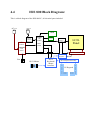
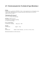
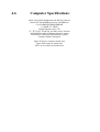
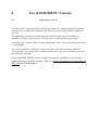
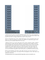
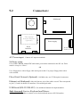
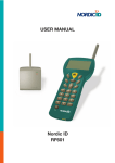
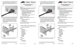
User Manual
ISIS 800 ISKM PC
Hazardous Area PC System
Contents
Chapter
1. Introduction
ISIS 800 ISKM PC Manual
2. Safety
General Safety Information
3. Unpacking
3.1
3.2
Unpacking the ISIS System
Receiving ISIS System
Unpacking ISIS System
4. Description
4.1
4.2
4.3
4.4
4.5
4.6
ISIS 800 ISKM PC System Description
System Description
ISIS 800 Unit Description
Mounting Bracket (Optional)
ISIS 800 Block Diagram
Environmental & Technical Specifications
Computer Specifications
5. Installation
5.1
5.2
5.3
ISIS 800 ISKM PC System Installation
ISIS 800 Unit Installation
Power-up Procedure
Uninstallation Procedure
6. Using System
6.1
6.2
6.3
6.4
Use of ISIS 800 ISKM PC System
General Notes of Use
ISIS Ex Membrane keyboard (if applicable)
ISIS Ex Mouse-Micromodule (if applicable)
Safety Procedure for Inspection of ISIS 800
7. Parts Specification
7.1
7.2
7.3
7.4
7.5
7.6
7.7
7.8
Parts Manufacturer Specifications (if applicable)
EOS VLT100-4000 Power Supply
PAPST 612 fan
INSIDE 786LCD/S Mainboard hardware
INSIDE 786LCD/S Mainboard software
SHARP LQ150X1DG11 LCD-panel
TDK CXA-0217 Backlight Inverter
AT-MC101XL Media Converter
IBM 30GN Series HDD
8. FAQ / Troubleshooting
8.1
8.2
8.3
8.4
8.4.1
8.4.2
8.4.3
8.4.4
8.4.5
9. Opening/Assembling
9.1
9.1.1
9.1.2
9.2
9.3
10. Certificate
Testing Procedures for ISIS System
FAQ ISIS 800 ISKM PC
Troubleshooting ISIS System on Site
Troubleshooting ISIS System for Repair
ISIS 800 Keypads & Mouse Test Procedure
(if applicable)
Connections
Software
Keypads
Mouse-Micromodule
Troubleshooting
Opening and Assembling Instructions
ISIS 800 Unit
Opening ISIS 800
Final Assembly
Connectors inside the ISIS 800 Unit
Enclosure Dimension Drawing
ISIS 800 Computer/Monitor/Terminal [DNV]
1
Introduction:
This manual covers all aspects of the ISIS 800 ISKM (Intrinsically Safe Keyboard Mouse) PC
system, from receiving/transport, installation and use of system to system diagnose and
maintenance.
Normal users only need chapter 1 to 6 (except chapter 3), chapter 7 to 9 is for support and
diagnosis of problems.
Chapter 1 – Introduction:
Manual organization and manufacturer information.
[All users]
Chapter 2 – Safety:
General safety information to help using the system and
understand the manual. [All users]
Chapter 3 – Unpacking:
Unpacking procedure when receiving the system.
[Logistics personnel only]
Chapter 4 – Description:
General description of the system, with pictures and
drawing. [All users]
Chapter 5 – Installation:
Installation and setup of the ISIS 800 PC system. [All
Users]
Chapter 6 – Using System:
Explanation of the user interface and safety procedures.
[All users]
Chapter 7 – Parts Specification:
Data from the manufacturers of the parts used in the ISIS
800 PC systems. (if applicable)
[Technical personnel]
Chapter 8 – FAQ / Troubleshooting: This is for support of the system. Use it as a reference
when necessary. [Technical personnel + operators]
Chapter 9 – Maintenance Information: Complete information for opening and
assembling of ISIS 800 enclosure. [Certified technical
personnel only]
Chapter 10 – Certificates:
Certificates for the Ex-parts of the system.
Manufacturer Information:
Technor ISIS Ltd
Main Office Address.
(Shipping Address for equipment repairs.)
Technor ISIS Ltd.,
The Cottage,
Martinholme Farm,
Thixendale,
Malton, UK.
YO17 9LP
Direct Lines
Telephone + 44 (0) 1759-368816
Fax + 44 (0) 1759 368514
mailto:[email protected]
http://www.technor-isis.com/
Notes
All electrical and computer specifications stated are only applicable for the following ISIS
TN800 serial numbers:
ISIS PC systems are delivered without software, and Technor ISIS should not be held liable
for software problems not recognized when the customer orders the equipment. Technor ISIS
may help the customer with operation system installation, but will not be held responsible for
software support of the operating system.
Last revised: August 2002
2
Safety Information:
ISIS 800 is approved by DNV for use in Zone 1, gas group IIB and temperature
class T5.
It is protected to IP 66. Operating temperatures 0° to +45° Celsius.
The ISIS 800 is explosion proof by design, and an eventual internal explosion
will not ignite any gas outside.
Never use the unit if the flame path (the flange) is damaged, glass is broken or
connectors/nipples damaged. These are vital parts to the safety.
Damage to the keyboard or mouse will not compromise safety, as these are
intrinsically safe, although the operator panel will cease to function.
Any modification or unauthorized repair of the ISIS 800 unit will void
certification.
Read manual thoroughly before attempting to install, use or service the system.
Warnings and cautions are issued several places in the manual, mainly for the
security of the personnel, but also to protect the equipment from damage.
3
Unpacking ISIS 800 PC:
Each ISIS 800 PC system is delivered in a single plywood container. The container is
strapped and secured with nails.
3.1
Receiving the ISIS 800 PC System:
1. Immediately upon receipt of system inspect container for visible damage. Notify
sending and transporting company if damaged. If there are no other procedures for
damaged goods, label container “Check contents for damages”.
2. If contents in container appear to be damaged or missing contact Technor ISIS as
soon as possible. (Telephone +44 1759-368816, fax: +44 1759 368514).
3.2
Unpacking the ISIS 800 PC System:
1. Remove all transportation papers on the outside of the container and store in a safe
place.
2. Remove packaging straps and the nails in the lid. Remove lid and Styrofoam spacer.
3. Remove the documentation.
4. Remove four Styrofoam corners from the ISIS 800 module
Caution: ISIS 800 weighs approximately 33 kg (70 lbs). Proper lifting techniques should
be used when moving/lifting the unit. Unit may damage other equipment or injure
personnel if not handled safely.
5. Remove the ISIS 800 PC unit. (Wrapped in foam).
6. Remove the rest of the Styrofoam.
7. Remove the sunscreen. (Optional)
4.1
ISIS 800 PC System Description:
Technor ISIS 800 PC system represents the state of the art in computing applications in
hazardous areas. There is no need for intrinsically safe interface or pressurized air-connection.
ISIS 800 unit are AC powered, auto-ranging from 100V to 240V. (50-60 Hz)
The ISIS 800 PC contains a 15” (38cm) TFT LCD display, an alphanumeric keyboard with
20 function keys and a pointing device. Rated IP66 it is designed for hazardous areas Zone 1
and Zone 2 both on- and offshore. Unit may be fitted with quick-release Ex d connectors for
ease of use and security.
The ISIS 800 starts its life as a compact aluminium alloy bar. Then it gets cut and machined
out, and is fitted with a 25mm (1”) security glass. Keyboard and mouse are integrated in the
front, cables exit at the bottom. Inside there are intrinsically safe circuits for keyboard and
mouse. A powerfull mainboard is runnung the show, and a universal power supply delivers
power to the electronics and the LCD display. Powerfull CPUs get a little warm, so a Pabst
fan ensures that the colours on the TFT-screen remain sharp and clear all the time. For
warmer climates there is an optional sunscreen to help viewability. Nothing is stronger than
its foundation, so Technor delivers optional custom-made mounting brackets and lifting
handles in solid SS316.
4.2
ISIS 800 System Description:
L
i
f
t
i
n
g
H
a
n
d
l
e
s
25mm thick Safety Glass
15” TFT LCD, 200 cd/m²
Left Keyboard
Mouse Micromodule
Right Keyboard
Ex d [ib] IIB
Ex Certification
Label
Blanking Plugs
Ground
Terminal
Power Cable Ethernet/USB/Serial Cable (Optional)
Technor ISIS 800 ISKM PC system represents the state of the art in computers for hazardous
areas. There is no need for intrinsically safe interface or pressurized air-connection. ISIS 800
unit are AC powered, auto-ranging from 100V to 240V. (50-60 Hz)
The ISIS 800 contains a 15” (38cm) TFT LCD display, an alphanumeric keyboard with 20
function keys and a pointing device. Rated IP66 it is designed for hazardous areas Zone 1 and
Zone 2 both on- and offshore.
Inside there is a powerfull P-III processor with SDRAM and HDD. Ethernet, Serial
(RS23/485) or USB might be used for communication.
The top, sides and back are machined cooling fins, all cables enter under the unit, and all
operations are done at the front.
Pictured lifting handles are optional.
Backside wiew:
4.3
Mounting Bracket (Optional)
& Lifting Handles (Optional)
The mounting bracket is made in 2mm AISI 316 stainless steel.
60mm
484mm
55mm
7mm
Lifting Handle
345mm
13mm Ø
152mm
180mm
152mm
4.4
ISIS 800 Block Diagram:
This is a block diagram of the ISIS 800 PC, all electrical parts included.
AC Input
Ethernet
HDD
5V
Power
Fiber
Optical
converter
(Optional)
INSIDE
786
LCD/S
CF-disk
(Optional)
LCD
Interface
(If applicable)
Mainboard
LCDPanel
12V
Power
CCFL Inverter
IS113
Brightness
Fan
IS131 Mouse
IS112
Keyboard/
Mouse
Interface
IS132 Keyboard Encoder
**
**
IS Keypads
**
**
**
******
** ******
******
** ******
**
**
**
**
**
**
**
4.5 Environmental & Technical Specifications:
Rating:
ISIS 800 unit is certified by CENELEC as Zone 1 rated equipment for use in hazardous areas,
without purge. ISIS 800 enclosure, keyboard and mouse-micromodule are rated IP 66.
Approvals: EEx [ib] IIB T5
Temperature: ISIS 800 system:
0˚ to +45˚ Celsius, operating.
-20˚ to +70˚ Celsius, non-operating.
Humidity: ISIS 800 system:
10 to 90% non-condensing, operating.
0 to 100% non-operating.
Power requirements:
100-240V AC, 50-60Hz,
Weight:
ISIS 800 unit:
Size:
ISIS 800 unit:
Max power : 70W
Approx. 31kg
464W x 336H x158D mm (18.3”W x 13.5”H x 6.3”D)
Machined aluminium AA 6082 enclosure.
4.6
Computer Specifications:
Inside 786 LCD/S Mainboard with SIS 630 Chipset
Intel P-III 700-850MHz Processor 100MHz bus
128-1024MB SODIMM SDRAM
10-60GB 2.5” HDD
Digital Interface for LCD
15” TFT LCD, 1024x768, 262 000 colors, 200 nits
100 Mbit Fiber Optical Ethernet Interface option
Serial (RS232/485) and USB Interface option
Compact Flash Card option
Spare PC Power connector inside unit
Spare IDE connector inside unit
IS152 service cable enclosed in box
5
ISIS 800 PC System Installation:
Optional lifting handles can make handling the ISIS unit easier and safer under installation
and uninstallation.
For mounting and protecting the system there is an optional mounting bracket and sunshade
made of SS316. The mounting bracket will usually be attached to the unit. (Sunshade is
attached on site after the unit is mounted up.)
5.1
ISIS 800 ISKM PC Unit Installation:
The ISIS 800 unit is designed for use anywhere else except in Ex Zone-0 or underwater. Local
power cable and communication cable(s) must be installed according to Safety Regulations
and local owners instructions. For custom-made mounting brackets contact Technor.
Caution: ISIS 800 weighs approximately 31 kg (66 lbs). Proper lifting techniques
should be used when moving/lifting the unit. Unit may damage other equipment or
injure personnel if not handled safely.
1. Inspect ISIS 800 unit and connectors/nipples for visible defects. Return unit to repair
if defects void Ex safety.
2. Optional: Lift the unit up to the mounting bolts using lifting eyes or handles. (See
separate mounting instructions for mounting bolts). Take care not to damage the
cables.
3. Optional: Slip the round section of the key holes on the backside of the ISIS 800 over
the bolt-head and lower carefully until the top of both slots are resting on the necks of
the bolts.
4. Optional: Verify that unit is safely secured before releasing the grip.
5. Optional: Mount the sunscreen on top of the unit by inserting the two tabs into the two
slots in the ISIS mounting brackets. Insert at an angle and lower the screen until it is
horizontal.
6. Connect Ground Terminal to ground (Earth) with a cable.
7. Inspect both power and communication-cables and connectors/nipples for damage.
8. Do not connect power to ISIS 800 before all communication-cables are connected.
5.2
1.
2.
3.
4.
5.3
Power-up Procedure:
Verify that power is 100-240V AC, 50-60Hz.
Connect all cables according to manual.
Power up ISIS 800 PC unit by supplying power to the powercable. There is no
powerswitch inside the unit.
Verify that all components are working. Allow 5-15 seconds for screen to brighten and
keyboard/mouse initialisation.
Uninstallation of ISIS ISKM PC System:
For uninstallation, use the installation instructions in reverse order. Start with switching
power off.
6
6.1
Use of ISIS 800 PC System:
General Notes of Use:
The ISIS 800 PC system generally works like an ordinary PC with an integrated mouse and
keyboard. Once installed there should be few differences from working with a computer in
safe area.
The alphanumeric keyboard is restricted in size. Some keys have up to five different
characters selected by four shift keys. Keyboard use is explained later in this chapter.
Some may not be familiar with the mouse-micromodule, there is also a short description about
it in this chapter.
The LCD is made for a resolution of 1024x768. Please select this resolution to get best
wieving quality. Use a larger font or different pointer size to get better readability instead of
decreasing the resolution.
Even if the ISIS 800 PC system is built for extreme conditions, it still needs
some observing for safety reasons. There is a Safety Procedure for Inspection of
ISIS 800 last in this chapter.
ISIS Ex membrane
Keyboard.
An ISIS keyboard consists of two IP66 membrane keypads with 50 keys total, mounted left
and right on the monitor front. Each key has a raised pressure point with tactile feedback. ISIS
keyboard-electronics is designed without auto-repeat for safety reasons.
There are 20 function keys F1-F20, of which function keys 13-20 will sometimes show up as
Shift+F1 to Shift+F8, depending on program used. IBM PC/AT standard has support for 20
function keys, but normally only the first 12 are used.
Alphabetic characters are written using numerical keys (like a telephone) together with three
special shift keys (Ashift). The three Ashift keys are placed at the left, and they need to be
pressed simultaneously with the numerical keys. Each Ashift-key chooses either left, middle
or right character on the numerical key. For capital letters, three keys need to be pressed
simultaneously, Shift+Ashift+numerical key. Special characters need software driver for
character remapping, or Microsoft Charactermap program. The punctuations !@#$%^&*()
are accessed as normal using Shift+numerical key, they are just hidden from the key-layout.
BS key means BackSpace, Del deletes to the right, Ins inserts, four arrows work as arrowkeys. Black(-) and white Sun(+)-keys adjust LCD screen brightness. (Note: This feature is not
included on all models)
The keyboard must never be operated with sharp objects such as screwdrivers etc.
ISIS Ex Mouse-Micromodule:
The Mouse-micromodule is an IP66 mouse-controller that consists of two mouse-keys and a
control-hat behind a stainless steel plate. The keys and hat are made of grey rubber. Both keys
have tactile feedback, and the hat is pressure sensitive in x-y plane. To control the mouse,
place a finger on the hat and push it gently in the direction you want. Release the hat to stop
pointer moving.
6.4 Safety Procedures for Inspection of ISIS800:
To maintain Ex-safety, the ISIS 800 unit needs to be inspected visually every time it is
powered. Never power on the unit in Zones 1 or 2 if the glass is broken, aluminium cracked or
connectors/nipples damaged, as the unit will not be explosion proof any more. Please contact
Technor ISIS if there is any uncertainty. (Telephone +44 1759-368816, fax: +44 1759
368514).
Damage to the integrated keyboard or mouse will not compromise safety, as these are
intrinsically safe, although the function of the operator panel will cease.
Any modification or unauthorized repair of the ISIS 800 unit will void certification.
The ISIS 800 enclosure has up to 11 openings: Back-lid, glass, mouse cable, two keyboard
cables, four blanking plugs and two connectors. 10 of these openings are sealed by the
manufacturer and need no maintenance.
The back-lid is secured by 28 M8 bolts, and the flange is part of the flame path. Each bolt
should be tightened to 30 Nm torque.
Before opening enclosure, read chapter 9.
The flame path should be inspected once a year under normal use for scratches and
mechanical damage. Always inspect after a repair or after unit has been opened. Remove
protective coating of acid free vaselin. Maximum roughness is 6.3µm. Contact manufacturer
for verification if in doubt. Never use the ISIS 800 if the flame path is damaged. Reapply a
thin layer of acid free vaselin on both parts of the flame path. Tighten all bolts to 30 Nm.
Any external connectors/cable glands are covered by their manufacturers own safety
instructions. Any visible damage should be checked to avoid electrical or Ex hazards.
8.1
FAQ ISIS 800 PC System:
1. What programs can the PC run? The PC can use any program the operating system
supports. Beware of using to powerfull operating system, there will be less CPU
power for the program.
2. Why goes the screen blank after 30 minutes of no activity? The operating system may
shut down the display to save power. Try to reconfigure the power saving settings to
settings that will suit better.
3. How do I switch the ISIS 800 PC ON/OFF? There are no keys for manually switching
it on or off, switch the power to the powercable or unplug the powercable. Use CTRL
+ ALT + DEL keys simultaneous for soft restart of the computer.
4. How many colours can the monitor display? Optically up to 262 thousand colours. It
will work fine with all colour-depths from 16 to 16 million colours.
5. Where are all the characters on the keyboard? All characters from A to Z are accessed
by a combination of an ASHIFT key and a numerical key (Chapter 6). This is a spacesaving feature. Typing is normally done with the local keyboard in safe area.
6. When I press and hold a key, nothing happens, why? ISIS keyboard is designed
without auto-repeat for safety reasons. A stuck key, for example, could wreak havoc in
a process.
7. Why is the ISIS 800 unit so heavy? An explosion proof capsule needs to be tough to
maintain constant Ex safety. The main body is made of machined aluminum alloy,
with 25mm glass in front of the LCD.
8. What maintenance does the ISIS 800 unit need? No daily maintenance, only cleaning
the screen with a damp cloth when necessary. Once a year the unit needs a routine
safety check. Never use the ISIS 800 unit if something is damaged.
9. Why will not USB work? USB only works under Windows 98 / ME / 2000 / XP and
some new Linux OS versions.
10. Why is the picture on screen best with 1024x768 resolution? Most 15” LCDs are made
for that resolution. Each point/pixel on LCD screen is fixed in size, not dynamically
sizable as on a CRT-screen. With a lower resolution pixels get joined like LEGObricks.
11. The system was ordered with xxxMB ram, why is the PC/OS reporting 16MB less than
stated? The graphic/video-processor is using the missing 16MB. The size of the videomemory can be adjusted in Bios-setup.
8.2 Troubleshooting ISIS800 system on Site:
1. Neither picture nor light on screen: Check power cable. Return unit to safe area for
repair.
2. No picture but light on screen: Try to access keyboard or mouse to wake up from
power saving mode. Return unit to safe area for repair.
3. Too dim/bright picture on screen: Use SUN keys on keyboard. Black-sun is dimming
and white-sun brightens screen. (Only implemented on high-bright LCD, standard
LCD are adjusted by operating system)
4. Picture on screen, part of picture missing: Select another screen-resolution (1024x768
preferred).
5. Picture on screen, coarse letters/details on screen: No defect, unfortunately a normal
LCD characteristic when using resolutions lower than intended. Select preferred
screen-resolution 1024x768.
6. Picture on screen, no response from keyboard: Try to restart computer. Return unit to
safe area for repair.
7. Picture on screen, partial response from keyboard: Try to restart computer. Return
unit to safe area for repair.
8. Picture on screen, no response from mouse: Check mouse for dirt/damage. Try to
restart computer. Return unit to safe area for repair.
9. Picture on screen, 2- second lag/freezing after moving mouse / pressing keys: No
fault, operating system might use power saving features after long inactivity.
10. Picture on screen, full response: Have a nice day!
8.3 Troubleshooting ISIS800 system for Repair:
Certified product.
No modifications permitted without the approval of the Certifying Authority.
Never open in hazardous area.
Certified personnel only! Read ISIS 800 OPEN/ASSEMBLE before opening.
No parts should be substituted without the approval of Technor ISIS.
1. Neither picture nor light on screen: Check power cable. Open unit, check AC input,
check 12VDC (Fan rotating?), and check power cable to LCD. Listen for beeps from
beeper on mainboard. Check mainboard manual for faultcodes. Check voltage on
small coin sized battery on mainboard, replace if below 2.5V. Return unit for repair.
2. No picture but backlight on screen: Listen for beeps from beeper on mainboard.
Check mainboard manual for faultcodes. Check voltage on small coin sized battery on
mainboard, replace if below 2.5V. Return unit for repair.
3. Picture on screen, coarse letters/details on screen: No defect. No LCD has dynamic
pixel-size. Reconfigure resolution to 1024x768.
4. Picture on screen, no response from keyboard: Follow “Test procedure ISIS800
keypads and mouse”
5. Picture on screen, partial response from keyboard: Follow “ISIS800 Keypads &
Mouse Test Procedure”
6. Picture on screen, no response from mouse: Follow “ISIS800 Keypads & Mouse Test
Procedure”
7. Picture on screen, full response: Have a nice day!
ISIS Keypads & Mouse Test Procedure.
This procedure tests the keypads, mouse, IS118/132 and IS128(112) through the integrated
computer in ISIS 700-800-900
1 Connections
1.1 For a thorough test of an assembled ISIS, connect all cables and make sure a floppy or a
harddisk drive with an OS is connected.
2 Software
2.1 Power up computer in DOS-prompt. Make sure a mouse driver is loaded in CONFIG.SYS
or AUTOEXEC.BAT. Run CHECKIT or similar test program in AUTOEXEC.BAT to
check the keys and mouse.
2.2 Microsoft Windows and Notepad can test all the other keys except the function keys.
Microsoft Windows can test the mouse without special drivers.
3 Keypad Test
3.1 Using CHECKIT, press SPACE-key twice to go to main menu. Press LEFT ARROW
once, UP arrow four times and ENTER three times. (Test, input device, keyboard,
enhanced 101-keys)
3.2 Press each button once to remove each highlighted key on the visual keyboard on the PC
screen. Use left, middle and right ASHIFT-keys to test alphabetic characters. (Note: F13
to F20 will show SHIFT+F1 to SHIFT+F8) Only one of the two SHIFT, CTRL and ALTkeys on the screen should work. None of the keys on the numerical keyboard at the right
of the screen should work.
3.3 Press a key three times to finish test. Answer Yes or No. ISIS keyboards do not autorepeat, press a key three times to finish next test. Answer Yes. No keyboard lights to light
up, answer Yes. Exit test.
4 Mouse Micromodule Test.
4.1 Using CHECKIT, choose TEST, INPUT DEVICE, and MOUSE. If a mouse driver is
loaded in CONFIG.SYS a mouse pointer should appear.
4.2 Verify on the screen that left and right mouse buttons work. Press ESC and skip test of the
middle button if the mouse driver detects the mouse as a 3-button mouse.
4.3 Verify full movement of mouse hat by following instructions on the screen.
5
Troubleshooting
Certified product.
No modifications permitted without the approval of the Certifying Authority.
Never open in hazardous area.
Certified personnel only! Read “ISIS 800 Opening/Assembling” before opening.
No parts should be substituted without the approval of Technor ISIS.
5.1 No response at all: Return ISIS for repair.
5.2 No response, PC beeping when using mouse: Mouse and keyboard-cable possibly
switched someplace between IS128 and mainboard. Return ISIS for repair.
5.3 No mouse response, keyboard OK: Make sure software driver is loaded if using DOS.
Check cable from micromodule to CN5 on IS128(112). Check cable IS153 from IS128 to
mainboard. Return ISIS for repair.
5.4 Mouse OK, no keyboard response: Check cable from IS118/132 to CN7 on IS128(112).
Key tabs should be flush with the connectors. Check flexi cable connectors on IS118/132,
no silver-plating on the connectors should be visible, and the connectors should be locked.
Check flexi cables for visible damage (cut/tears). Check keypads for visible faults. Return
ISIS for repair.
5.5 Mouse OK, partial keyboard response: Note if problem is exclusively left or right keypad,
pay special attention to that side. Check flexi cable connectors on IS118/132, no silver
plating on the connectors should be visible, and the connectors should be locked. Check
flexi cables for visible damage (cut/tears). Check keypads for visible faults. Return ISIS
for repair.
9.1
Opening/Assembling ISIS 800 Unit:
Certified product.
No modifications permitted without the approval of the Certifying Authority.
Never open in hazardous area.
Certified personnel only! Read all instructions before opening.
No parts should be substituted without the approval of Technor ISIS.
9.1.1
Opening ISIS 800:
Unplug all external cables.
Caution: ISIS 800 weighs approximately 33 kg (70 lbs). Proper lifting techniques
should be used when moving/lifting the unit. Unit may damage other equipment or
injure personnel if not handled safely.
Place the ISIS 800 backside up on a clean steady desk with a soft layer under to protect the
front. Use 6mm Allen key tool to loosen the 28 bolts. Remove the bolts and back plate, take
care storing the back plate so nothing damages the flame path. Mount a flame path-protector
over the flange using 4 bolts.
Caution: Damage to the flame path will void the Ex safety, and the unit must be
returned to manufacturer for repair/exchange of enclosure.
ESD Hazard: Delicate equipment inside, use ESD ground-strap when working inside
ISIS 800.
Shock Hazard: Dangerous voltages inside, allow 10 minutes for power capacitors to
drain after power has been switched off.
Caution: Damage to the flexi prints from the front to IS118 is not repairable, and the
unit must be returned to manufacturer for repair/exchange of cable.
Caution: Damage to the Mouse-cable from the front to the IS128 may not be
repairable, and the unit must be returned to manufacturer for repair/exchange of cable.
9.1.2
Final Assembly:
Place the ISIS 800 backside up on a clean steady desk with a soft layer to protect the front.
Remove the flame path-protector from the flange by removing the four bolts.
Caution: Damage to the flame path will void the Ex safety, and the unit must be
returned to manufacturer for repair/exchange of enclosure.
Remove possible dirt from the flange and carefully replace back plate. Insert 28 Allen head
M8 25mm SS bolts in the bolt holes. Use 6mm Allen key tool to tighten the 28 bolts in crosspattern to 30 Nm.
Caution: ISIS 800 weighs approximately 33 kg (70 lbs). Proper lifting techniques
should be used when moving/lifting the unit. Unit may damage other equipment or
injure personnel if not handled safely.
9.2
Connectors:
Fan
Mainboard
Net
work
U
S
B
Fiber Optical
Network Interface
(Optional)
IDE
ST
ST
Power supply
IS128
Interface
IS152
AC Power input:
Floppy
AC Power Input
100-240V, 50-60Hz
MS kbd
Connect AC input to terminals.
Software setup:
Use an IDE CDROM with an IDE cable and a powercable connected to the DC out. Drive
must be set up as a “Slave”.
OR
Use a floppy drive with a floppy cable and a powercable. Use proper floppy cable with 6
wires twisted.
Fiber Otical Network (Optional): 100 Mbit only, use ST fiberoptical connectors.
Ethernet on Mainboard: Only the first two pair of the cables is used. This corresponds
to pin 1,2,3 and 6 in the RJ-45 connector. Use twisted pair cable.
USB/Serial (RS-232/RS-422): See mainboard manual for implementation.
Safe Area only Service Keyboard and Mouse:
Use supplied IS152 cable to connect service keyboard and mouse to IS128 interface.
9.3
Enclosure Drawing