1
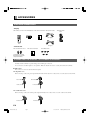
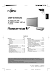
English
USER’S MANUAL (1/2)
(Functions and connections)
WIDE PLASMA DISPLAY
P42VCA30W/P42VCA30E
WITH OPTIONAL VIDEOBOARD
(P-TE1100/P-TE1110/P-TE1120/P-TE1130)
HE4VS01W/HE4VS01E
WITH OPTIONAL VIDEOBOARD (HETES01/HETES02)
Contents
•
•
•
•
•
•
Page
Accessories ······················································ E-2
Part Names and Functions ······················· E-3–E-6
Installation ······················································· E-7
Options ······················································ E-8–E-9
Factory Settings ············································ E-10
Specification ··················································· E-11
Before Use
• Safety Precautions ··············· User’s manual (2/2)
Usage
• Using the Remote Control ··· User’s manual (2/2)
• Connecting the Display to External
Equipment ···························· User’s manual (2/2)
• Basic Operations ·················· User’s manual (2/2)
• Selecting Input Mode ··········· User’s manual (2/2)
• Watching Pictures on the Wide Screen
··············································· User’s manual (2/2)
Adjustments
• Adjusting Pictures (PICTURE Menu)
··············································· User’s manual (2/2)
• Adjusting Screen Position and Size
(POSITION/SIZE Menu) ········ User’s manual (2/2)
• Adjusting Audio (AUDIO Menu)
··············································· User’s manual (2/2)
• Other Adjustments
(FEATURES Menu) ··············· User’s manual (2/2)
• Initialization of User Adjustment Value
(FACTORY DEFAULT) ··········· User’s manual (2/2)
• Cleaning and Maintenance ··· User’s manual (2/2)
Before using the display, read the User’s manual (1/2) and the User’s manual (2/2) carefully so that you know how
to use the display correctly.
Refer to these manuals whenever questions or problems about operation arise. Be sure to read and observe the
safety precautions.
Keep these manuals where the user can access them readily.
* Installation and removal require special expertise. Consult your product dealer for details.
E-Plasma-wide1(hyo1)
Page 1
03.7.8, 5:45 PM
Adobe PageMaker 6.5J/PPC
ACCESSORIES
CHECKING ACCESSORIES
• Display
One remote control Two AA batteries Two user’s manuals One power cable
Two big ferrite
cores
(W Type)
(E Type)
• Video board
Two small ferrite cores
Two user’s manuals
Five M3 screws
(supplied on models
with external speaker
output terminals)
CONNECTING THE DISPLAY TO EXTERNAL EQUIPMENT
Carefully check the terminals for position and type before making any connections.
Loose connectors can result in picture or color problems. Make sure that all connectors are securely inserted into their terminals.
Ferrite cores
These ferrite cores are used to attenuate undesired signals.
Two big ferrite cores
When connecting a cable to the power input terminal, RS-232C terminal, attach one of these ferrite cores to the cable near the terminal.
Power Cable
RS-232C Cable
Ferrite Core
Ferrite Core
Two small ferrite cores
When connecting a cable to the external speaker output terminal attach one of these ferrite cores to the cable near the terminal.
Ferrite Core
Ferrite Core
E-2
E-Plasma-wide1 (02)
Page 2
03.7.8, 5:46 PM
Adobe PageMaker 6.5J/PPC
English
PART NAMES AND FUNCTIONS
Front
1 Power indicator lamp
This lamp shows the state of the power supply.
Lit (red):
Power OFF (stand-by)
Lit (green):
Power ON
Lit (orange):
Power saving (DPMS: Power
saving function) mode ON
Flashing (red or green): Malfunction (Flashes differently
depending on the type of
malfunction.)
①
②
2 Remote control signal receiver
Receives signals from the remote control.
Warning
If the power indicator lamp flashes red or green, this signifies that the display has developed a problem. When this happens, be sure to
remove the power plug from the receptacle and contact your dealer. Leaving the display power ON can result in fire or electric shock.
E-3
E-Plasma-wide1(03-07)
Page 3
03.6.12, 3:32 PM
Adobe PageMaker 6.5J/PPC
PART NAMES AND FUNCTIONS (Continued)
Back and bottom (With the video board)
1 OFF/STD-BY
switch
OFF
:The power indicator lamp goes off, and the power can’t be turned on by the power button. The power is partly supplied.
STD-BY
:The power indicator lamp lights red, and the power can be turned on or off by the power button.
2 RS-232C terminal (RS-232C)
This terminal is provided for you to control the display from the PC. Connect it to the RS-232C terminal on the PC.
When connecting a cable, attach a ferrite core to the cable. (See P. E-2.)
3 RGB1 input terminal (RGB1 INPUT/mD-sub)
Connect this terminal to the PC’s display (analog RGB) output terminal or decoder (digital broadcast tuner, etc.) output terminal.
4 Power input terminal
Connect this terminal to the power cable supplied with the display.
When connecting a cable, attach a ferrite core to the cable. (See P. E-2)
E-4
E-Plasma-wide1(03-07)
Page 4
03.6.12, 3:32 PM
Adobe PageMaker 6.5J/PPC
English
5 External speaker output terminal (EXT SP)
Connect this terminal to the optionally available speaker.
(When using other speaker than the optional one, use 4–16 Ω speaker.)
When connecting a cable, attach a ferrite core to the cable. (See P. E-2.)
6 Sound 1 input terminal (AUDIO1 INPUT)
7 Sound 2 input terminal (AUDIO2 INPUT)
8 Sound 3 input terminal (AUDIO3 INPUT)
Connect this terminal to the sound output terminal of your VCR, etc.
* The Sound 3 input terminal (AUDIO3 INPUT) is not available for the video board P-TE1110/HETES02.
9 RGB2 input terminal (RGB2 INPUT/BNC)
Connect this terminal to the PC’s display (analog RGB) output terminal.
0 RGB2 synchronization switch (SYNC SW TTL/ANALOG (75 Ω))
This switch is used to terminate horizontal (H) terminal and vertical (V) terminal, out of RGB2 input terminals, with 75 Ω.
TTL
: Does not terminate.
ANALOG (75 Ω) : Terminates.
A S-Video input terminal (S VIDEO INPUT)
Connect this terminal to the S-video output terminal of your VCR.
B Video input terminal (VIDEO INPUT)
Connect this terminal to the video output terminal of your VCR.
C Video board (Optional)
* Terminal layout may differ and functions may not be available with some models and some device options.
E-5
E-Plasma-wide1(03-07)
Page 5
03.7.8, 5:46 PM
Adobe PageMaker 6.5J/PPC
PART NAMES AND FUNCTIONS (Continued)
Description of Input Terminals
RGB1 terminal (RGB1 INPUT/mD-sub)
RS-232C terminal (RS-232C)
Pin No. Input signal
Pin No.
Input signal
1
Red
9
—
2
Green
10
Ground
3
Blue
11
—
4
—
12
—
5
Ground
13
Horizontal synchronization
6
Ground
14
Vertical synchronization
7
Ground
15
—
8
Ground
Frame
Ground
Pin No.
Signal
1
DCD (Data Carrier Detect)
2
RD (Received Data)
3
TD (Transmit Data)
4
DTR (Data Terminal ready)
5
GND (Ground)
6
DSR (Data Set Ready)
7
RTS (Request To send)
8
CTS (Clear To Send)
9
RI (Ring Indication)
E-6
E-Plasma-wide1(03-07)
Page 6
03.6.12, 3:32 PM
Adobe PageMaker 6.5J/PPC
English
INSTALLATION
To prevent the display’s internal components from overheating, make sure that the display is installed in a well-ventilated location.
Be sure to use the optional desktop stand, ceiling-mounting unit, wall-mounting unit and other unit when installing this display. Also, be
sure that your dealer performs the installation.
See the appropriate instruction manual for more information on the installation hardware you select.
To ensure proper heat radiation, provide at least as much space around the display as shown below.
* Make sure that the display is installed in a location where the temperature can be maintained between 0°C and 40°C.
* Install this device in a well-ventilated area. Keep the air vents of the device free from obstruction.
* Never attempt to tilt the display sideways or backward.
* To prevent the power and other cables from being accidentally pulled, be sure to make the wiring work along the wall or through the
corners of floor.
* To prevent an accident and ensure safety in the event of an earthquake, fix the display securely into position as described below.
Horizontal type
Side
Front
(cm)
(cm)
Upper
10
Left
10
10
Right
Wall
5
Lower
3.5
Note
The display is a highly precise piece of equipment and therefore must be packed properly before transportation. Be sure to use only those packing
materials originally supplied with the display when repacking it.
Reference
See P.E-8 for more information on options.
E-7
E-Plasma-wide1(03-07)
Page 7
03.6.12, 3:32 PM
Adobe PageMaker 6.5J/PPC
OPTIONS
Wall-mounting Bracket
0° to 15° mounting angle
P-WB4201
Ceiling unit
0° to 15° mounting angle
P-CT4200
Desktop Stand unit
P-TT4200
Speaker system
P-42SP11
(1 set of 2 speakers)
Desktop Speaker Stand
P-42ST11
(1 set of 2 speakers stands)
Videoboard
• P42VCA30
Designation
Terminal
RGB2 terminal
P-TE1100
Speaker terminal
Video, S-video
—
—
P-TE1110
—
P-TE1120
—
P-TE1130
• HE4VS01
Designation
Terminal
RGB2 terminal
Speaker
HETES01
(internal)
HETES02
(internal)
Video, S-video
—
* When installing an option, make sure that all installation requirements for that option (as given in the relevant instruction manual) are met.
* The colors of options do not match the display colors perfectly.
* To improve the function and performance of optional accessories, specifications and part names may change. Consult your local dealer
before purchasing.
Warning
To prevent injury, fire, and electric shock, arrange for options to be initially installed (or installed at a different location) by your dealer.
CAUTION: This display (P42VCA30, HE4VS01) is for use only with Fujitsu General Limited’s option (PWB4201, P-CT4200, P-TT4200).
Using this display with other option can cause instability resulting in possible injury.
E-8
E-Plasma-wide1(08-11)
Page 8
03.7.9, 5:00 PM
Adobe PageMaker 6.5J/PPC
English
INSTALLING THE VIDEO BOARD
1. Turn the power supply switch to OFF.
2. Remove the power plug from outlet.
3. Remove the metal fittings on the installation position at the rear of
this device (M3 screw x 2).
4. Slide the video board into the installation opening along the left
and right guide pins and insert the connectors.
5. Use the accompanying screws to secure (M3 screw x 5, accompany
video board).
CAUTION: Follow the items given below, to prevent accidental injuries and possible electrical shock.
Turn off the power supply and disconnect the power plug from outlet before installing the Video board unit.
Do not remove the cabinet when installing the Video board unit.
Do not remove screws expect for the specified user service screw marked “ ”.
Do not use screws other than that specified in this manual for the installation of this Video board unit.
E-9
E-Plasma-wide1(08-11)
Page 9
03.6.12, 3:32 PM
Adobe PageMaker 6.5J/PPC
FACTORY SETTINGS
This display can store the latest four types of signals for RGB adjustment value. The fifth input signal will delete the adjustment value of
the first input signal.
To do this, select a desired signal and follow the instructions in “Adjusting Screen Position and Size” on the User’s Manual (2/2) to adjust
the parameters. When you finish, the settings will be automatically stored. Thus, when the display receives that signal, pictures will be
displayed in accordance with the settings you most recently selected.
Main corresponding signals (RGB mode)
Display (dots x lines)
Horizontal frequency (kHz)
Vertical frequency (Hz)
Signal
640 x 480
31.47
59.94
VGA
640 x 480
37.50
75.00
VGA 75 Hz
640 x 480
43.27
85.01
VGA 85 Hz
720 x 400
31.47
70.09
400 lines
800 x 600
37.88
60.32
SVGA 60 Hz
800 x 600
46.88
75.00
SVGA 75 Hz
800 x 600
53.67
85.06
SVGA 85 Hz
1024 x 768
48.36
60.00
XGA 60 Hz
1024 x 768
60.02
75.03
XGA 75 Hz
1024 x 768
68.68
84.99
XGA 85 Hz
1280 x 1024
63.98
60.02
SXGA 60 Hz
1280 x 1024
79.98
75.03
SXGA 75 Hz
1600 x 1200
75.00
60.00
UXGA 60 Hz
1600 x 1200
106.25
85.00
UXGA 85 Hz
848 x 480
31.02
60.00
852 x 480
31.72
59.97
1360 x 768
47.71
60.01
720 x 485
15.73
59.94
60 fields
720 x 575
15.63
50.00
50 fields
* With some input signals, “Out of range” may appear even when the horizontal and vertical frequencies are within their permissible ranges. Make
sure that the vertical frequency of the input signal matches the above frequency.
In the Video/S-video modes, the display has been factory-set as follows for different input signals:
Main corresponding signals (Video, S-video mode)
Horizontal
frequency (kHz)
•
•
•
•
•
•
Vertical
frequency (Hz)
Signal
15.73
59.94
NTSC
15.63
50.00
PAL
15.63
50.00
SECAM
15.63
59.52
PAL60
15.73
59.94
4.43NTSC
Depending on the input signal, the display may show pictures of reduced size due to size reduction and interpolation.
“Out of range” appears if the display receives a signal whose characteristic does not fall within the display’s permissible range.
You can check input signals through “Information” on the FEATURES Menu screen. (See User’s Manual (2/2))
In order to facilitate the explanations, pictures and diagrams in this manual may differ slightly from the actual items.
All terms (i.e., company and product names) used in this document are trademarks or registered trademarks.
Functions may be different or unavailable with some models and some device options.
E-10
E-Plasma-wide1(08-11)
Page 10
03.6.13, 7:08 PM
Adobe PageMaker 6.5J/PPC
Model
English
SPECIFICATION
P42VCA30W/P42VCA30E
HE4VS01W/HE4VS01E
Screen size
42" wide screen:
92.0 cm (W) x 51.8 cm (H) (106.0 cm diagonal)
36.3 inch (W) x 20.4 inch (H) (41.6 inch diagonal)
Aspect ratio
16:9 (wide)
Weight
31 kg / 68 lbs
Outer dimensions
103.5 (W) x 64.0 (H) x 8.5 (D) cm
40.7 (W) x 25.2 (H) x 3.3 (D) inch
31.5 kg / 69.4 lbs
Power supply
110-240 VAC 50/60Hz
Current rating
4.1–1.9 A
Number of pixels
852 (H) x 480 (V)
Colors
16.77 million
(does not include outer projections)
Sound output
—
2 W + 2 W (EIAJ), 8 Ω
(only with video board installed)
Speaker
—
2-internal (only with video board installed)
Operating conditions
Temperature: 0 to 40 °C / 32 to 104 °F
Humidity:
20 to 80 %
External equipment terminals
RGB1 input
mD-sub, 3 rows, 15-pin
Picture signal: 0.7 Vp-p/75 Ω
Synchronization signal:TTL level
Constrol terminal
1 RS-232C connector (D-sub 9-pin)
* The video board input specifications conform with those provided below.
* Terminals may not be available with some video board models.
* Consult your local dealer before purchase.
External equipment terminals
0.7 Vp-p/75 Ω
0.7 Vp-p/75 Ω
0.7 Vp-p/75 Ω
TTL Level or ANALOG (75 Ω)
TTL Level or ANALOG (75 Ω)
RGB2 input
BNC terminal x 5 R:
G:
B:
H:
V:
Video input
1 BNC terminal
1 Vp-p/75 Ω
S-video input
1 S terminal
Y: 1 Vp-p/75 Ω
C: 0.286 Vp-p/75 Ω
Sound terminals
2 sound input pin jacks (L/R) (3 lines), 500 mVrms/ at least 22 kΩ
(The Sound 3 input terminal (AUDIO3 INPUT) is not available for the video board P-TE1110/HETES02.)
External speaker output terminal
Effective max. output:10 W + 10 W (EIAJ), 8 Ω
—
Regulation
• UL, CSA Safety: UL6500, C-UL
EMC: FCC Part 15 Class A, ICES-003 Class A
• CE Safety: EN60065
EMC: EN55022
1998, Class A
EN61000-3-2
1995
EN61000-3-3
1995
EN55024
1998
EN61000-4-2
1995
EN61000-4-3
1996
EN61000-4-4
1995
EN61000-4-5
1995
EN61000-4-6
1996
EN61000-4-8
1993
EN61000-4-11 1994
• AS Safety: IEC60065
EMC: AS/NZS 3548
• Specifications and external appearance may be change for the sake of improvement.
•
is a worldwide trademark of Fujitsu General Limited and is a registered trademark in Japan, the U.S.A. and other countries or areas.
E-11
E-Plasma-wide1(08-11)
Page 11
03.7.8, 5:47 PM
Adobe PageMaker 6.5J/PPC