1
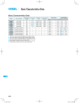
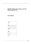
DEVA011 Quadrature Signal Generator card
Issue 2.0
User’s Manual
A
B
M
Data
Clock
V2.0
52 Woodside Business Park
Birkenhead
Wirral CH41 1EL
United Kingdom
Tel +44 (0)151 647 3222
Fax +44 (0)151 647 4511
Email: [email protected]
Web: www.deva.co.uk
Deva Electronic Controls Ltd. provides all technical information and particulars of the product
and its use, in good faith. However, it is acknowledged that there may be errors and
omissions in this manual. We shall not be liable for loss or damage whatsoever arising from
the use of any information or particulars in, or any omissions from, this document.
V2.0
DEVA011 PCI User’s Manual
Overview
1
Overview ........................................................................ 1
1.1
Product Features .....................................................................1
1.2
Typical applications.................................................................2
1.2.1
1.2.2
1.2.3
1.2.4
Automatic testing of incremental encoder interfaces............................2
Drive and encoder system simulation .....................................................2
Laboratory frequency generator ..............................................................2
Stepper motor drive logic .........................................................................2
1.3
Software support .....................................................................3
1.3.1 Microsoft Windows 98 / NT4 / 2000 / ME / XP support ...........................3
1.3.2 Generator Digital Readout software (GENDRO) .....................................3
1.4
Accessories..............................................................................3
2
Installation and configuration...................................... 4
2.1
Software support CDROM .......................................................4
2.2
PCI Plug and Play cards ..........................................................4
2.2.1 System requirements ................................................................................4
2.2.2 Card Installation.........................................................................................4
2.2.3 Device driver installation ..........................................................................5
2.2.3.1 Windows 98 / ME / 2000 / XP installation ............................................................................. 5
2.2.3.2 Windows NT4 installation ..................................................................................................... 5
3
Device Driver Usage ..................................................... 6
3.1
Device driver functions ...........................................................6
3.1.1
3.1.2
3.1.3
3.1.4
3.1.5
3.1.6
3.1.7
3.1.8
System information ...................................................................................6
Channel information..................................................................................6
Position information..................................................................................7
Timer information ......................................................................................7
Input event information .............................................................................8
Digital I/O information ...............................................................................8
Software call-back information ................................................................8
Channel Group information ......................................................................8
i
Overview
DEVA011 PCI User’s Manual
3.1.9 Channel information ............................................................................... 10
3.1.10 Channel event information ..................................................................... 11
3.2
Function compatibility...........................................................12
3.3
Device driver programming from ‘C’ ....................................13
3.3.1
3.3.2
3.3.3
3.3.4
3.3.5
3.3.6
3.3.7
long open_gen (void) .............................................................................. 13
void close_gen (void).............................................................................. 13
long read_gen (long command, long param) ....................................... 13
void write_gen (long command, long param, long value) ................... 13
long genlib_version (void) ...................................................................... 13
long genlib_callback (long receive, long priority);............................... 14
Example 'C' programming ...................................................................... 14
3.4
Device driver programming from Visual Basic....................15
3.4.1 Function open_gen () As Integer ........................................................... 15
3.4.2 Function close_gen () As Integer........................................................... 15
3.4.3 Function read_gen (ByVal com As Long, ByVal chan As Long) As
Long.......................................................................................................... 15
3.4.4 Function write_gen (ByVal com As Long, ByVal chan As Long, ByVal
value As Long) As Integer ...................................................................... 15
3.4.5 Function genlib_version () As Long ...................................................... 16
3.4.6 Example Visual Basic Programming..................................................... 16
4
Hardware ......................................................................17
4.1
Functional description ..........................................................17
4.1.1 Quadrature output................................................................................... 17
4.1.2 Count control register............................................................................. 18
4.1.3 Count width register ............................................................................... 18
4.1.4 Count value register................................................................................ 19
4.1.5 Marker output .......................................................................................... 20
4.1.6 Auxiliary output ....................................................................................... 20
4.1.7 Timer and Timer interrupt....................................................................... 20
4.1.8 Move load events, move complete events and interrupts ................... 20
4.1.9 Count FIFO status flags .......................................................................... 21
4.1.10 Digital IO................................................................................................... 21
ii
DEVA011 PCI User’s Manual
Overview
4.2
Connection details.................................................................22
4.3
Quadrature output connections............................................22
4.3.1 Digital IO connections.............................................................................23
4.3.1.1 Digital IO connector 0 connections.................................................................................... 23
4.3.1.2 Digital IO connectors 1 and 2 connections ....................................................................... 24
4.3.2 Sync connector ........................................................................................24
4.4
Direct hardware programming..............................................25
4.4.1 Register address map .............................................................................25
4.4.1.1 Offset 00h – Special function control register 0 ............................................................... 27
4.4.1.2 Offset 00h – Special function status register 0 ................................................................. 27
4.4.1.3 Offset 04h – Special function control register 1 ............................................................... 27
4.4.1.4 Offset 08 – Interrupt mask register .................................................................................... 28
4.4.1.5 Offset 08 – Interrupt request register ................................................................................ 28
4.4.1.6 Offset 0Ch – Timer 0 latch .................................................................................................. 29
4.4.1.7 Offset 0Ch – Timer 0 counter ............................................................................................. 29
4.4.1.8 Offset 20h, 24h, 28h – Digital I/O control / status register................................................ 29
4.4.1.9 Offset 20h, 24h, 28h – Digital I/O direction register .......................................................... 29
4.4.1.10 Offset 40h, 44h, 48h – Channel control register............................................................. 29
4.4.1.11 Offset 40h, 44h, 48h – Channel status register .............................................................. 30
4.4.1.12 Offset 60h, 64h, 68h – Channel current counter ............................................................ 30
4.4.1.13 Offset 60h, 64h, 68h – Channel next count value register............................................. 30
4.4.1.14 Offset 80h, 84h, 88h – Channel current count control register..................................... 31
4.4.1.15 Offset 80h, 84h, 88h – Channel next count control register.......................................... 31
iii
DEVA011 PCI User’s Manual
1
Overview
Overview
The DEVA011 PCI three channel quadrature signal generator card has been
designed to produce three channels of independently generated quadrature counts
using a PC based system. It can be used for a wide range of testing applications,
such as the soak testing of measurement systems, square wave signal generation
and open-loop motion control applications.
1.1
Product Features
The card is derived from Deva's own quadrature technology, and has the following
features:
•
Three channels with differential quadrature outputs.
•
24 bit count command registers.
•
24 bit count width registers.
•
30ns or 1µs count width pre-scaler option per channel.
•
Count complete marker output on each channel.
•
Auxiliary output on each channel.
•
Two limit inputs per channel.
•
Quadrature signal read back.
•
Interrupt generation when counting completes.
•
8 bit interval timer with interrupt generation.
•
48 TTL level digital IO
•
+5v and +/-12v power supplies available on connectors.
Page 1
Overview
1.2
DEVA011 PCI User’s Manual
Typical applications
The following few examples illustrate how the DEVA011 may be effectively used in
practical applications.
1.2.1 Automatic testing of incremental encoder interfaces
The DEVA011 quadrature generator can be used to produce predetermined patterns
of pulses with or without a marker pulse. The frequency of the quadrature counts can
be set from 0.015Hz to 33.3MHz. The ability to generate a pre-determined number,
direction and count rate of quadrature counts, can be used as a reference to ensure
correct reading of an the encoder interface. Since the generator complies with the
RS-422 differential signal standard, each channel may be used to drive ten receivers
in parallel (or more, depending on the cable lengths). This facility can be used to
soak test many encoder reading devices at the same time.
1.2.2 Drive and encoder system simulation
Using an additional analogue to digital converter board, the quadrature counts that
would be generated when a driver system is commanded to move, could be
simulated. The speed of count generation would be set by the Count Width Register
and the counts generated by writing values to the Count Value Register. As the
analogue reading reduces, the count width should increase. The response time of
the generator will be set by the execution time of the commands. It is therefore
necessary to reduce the size of count commands while generating slow counts.
The DEVA011 generator can be used to exercise a control system, by providing the
quadrature counts that would have come from incremental encoders on a mechanism.
The control system might need to react in some way at a certain quadrature count
value.
1.2.3 Laboratory frequency generator
In this application the A or B signals can be used separately as square wave signals.
The frequency can be set by the count width register. Additionally this can be scaled
by the use of the pre-scaler. If a mark space ratio signal is required the marker signal
could be used. If a pattern is pre-calculated, it can be loaded to the count FIFO
buffer.
1.2.4 Stepper motor drive logic
With the use of a power amplifier, the DEVA011 can be used to drive four phase
stepper motors. The driving software has to manage the count width and ensure that
the next command is pre-loaded, to give a continuous count generation. The count
width would start at a high value (slow rate) and increase until at full speed.
Page 2
DEVA011 PCI User’s Manual
1.3
Overview
Software support
A variety of software drivers and libraries are provided with the card to enable
software development to be performed within a number of operating systems and
applications. Software support is an ongoing activity, if support for a particular
application or operating system is not currently provided please contact Deva to
determine its availability.
1.3.1 Microsoft Windows 98 / NT4 / 2000 / ME / XP support
DEVA011 PCI cards are supported in Microsoft Windows 98 / NT4 / 2000 / ME / XP
operating systems, by software Kernel Mode Drivers (KMD) or Windows Driver Model
(WDM) drivers. All drivers support a standard programming interface. Please refer to
section 3 for more details.
1.3.2 Generator Digital Readout software (GENDRO)
A powerful digital readout is supplied which is capable of exercising all the common
facilities of the DEVA011. This is useful to allow users to quickly verify that the
DEVA011 is installed correctly and to make checks of their system without having to
write their own software.
GENDRO can handle multiple DEVA011 cards. It allows control of the number of
counts, count rate, various count modes, marker and auxiliary outputs. Also it
displays the current count and limit input states.
To allow the user to read meaningful values each channel of the GENDRO may be
independently scaled to display real units.
1.4
Accessories
The DEVA011 quadrature signal generator card is supplied with three high density 15
way 'D' type connectors and matching shells.
Page 3
Installation and configuration
2
Installation and configuration
2.1
Software support CDROM
DEVA011 PCI User’s Manual
The DEVA011 three channel quadrature signal generator card is supplied with a
software support CD-ROM containing support for DEVA011 cards along with support
and information for many of Deva’s other products. The CDROM includes the
following items:
Windows 98 / NT4 / 2000 / ME / XP device drivers providing coherent quadrature
signal generator card hardware management.
Windows 98 / NT4 / 2000 / ME / XP dynamic link library (DLL) and import library
containing the driver access functions.
'C' language library routines and header files which create a simple interface to
device driver functions.
Example 'C' programs illustrating card read / write using device driver functions.
Visual Basic Module which provides constant and function definitions to allow simple
DLL access.
Example Visual Basic programs illustrating card read / write using device driver
functions.
Demonstration Digital Readout program for Windows.
2.2
PCI Plug and Play cards
2.2.1 System requirements
The device driver library functions and the demonstration software require an IBM PC
compatible (486 or above recommended) with one spare PCI slot.
System processor requirements for use with Windows will depend on the application
but at least a Pentium processor is recommended.
2.2.2 Card Installation
The DEVA011 requires 4k bytes of memory space which is automatically assigned
by the Plug and Play manager (OS/BIOS) when the computer boots with the card
installed. The card is installed by inserting it into any available PCI slot.
Page 4
DEVA011 PCI User’s Manual
Installation and configuration
2.2.3 Device driver installation
2.2.3.1 Windows XP / 2000 / ME / 98 SE installation
During the first boot after the card has been installed windows will indicate that a new
PCI device has been found and will start the standard driver installation procedure. If
this does not occur it is possible to initiate this process manually via the ‘add new
hardware’ icon in the control panel or via the windows device manager.
Follow the instructions and when requested select ‘specify a location’ and then
browse to the directory on the installation CDROM containing the deva011.inf file.
For example for Win2000 select:
\PC interface products\Deva011\Issue2.x\Drivers\Win2000\deva011.inf
Click ok and follow instructions to complete the installation.
The installation may be tested using the supplied GENDRO program, which may be
found on the CD in the utils\win32 directory.
2.2.3.2 Windows NT4 installation
To load the Windows NT driver go to the WinNT directory on the CDROM for the
relevant product and locate the deva011.inf file. For example:
\PC interface products\Deva011\Issue2.x\Drivers\WinNT\deva011.inf
Right click on the file and select install. A message will be displayed to indicate
successful installation. It is now necessary to re-boot the computer.
The installation may be tested using the supplied GENDRO program, which may be
found on the CD in the utils\win32 directory.
Page 5
Device Driver Usage
DEVA011 PCI User’s Manual
3
Device Driver Usage
3.1
Device driver functions
The supplied Windows NT4 / 98 / ME / 2000 / XP device drivers provide a simple
method of accessing card functions and remove the need for direct register
programming. Use of the device driver ensures that the user's application software is
compatible with other Deva products and is protected from any future changes in the
card hardware or register layout. The device driver automatically determines the total
number of channels and I/O available from all the cards in a system. This section
describes the functions provided by the device driver whilst the compatibility chart at
the end of the section details the functions available from particular cards.
3.1.1 System information
Command & equate
Param. Rd/Wr
Operation
1
NUM_CHANNELS
N/A
Rd
Returns the total number of axis channels
available from the installed cards.
2
NUM_TIMERS
N/A
Rd
Returns the total number of timers available from
the installed cards.
7
NUM_BOARDS
N/A
Rd
Returns the number of generator cards present in
the system.
8
CARD_TYPE
N/A
Rd
Returns the card type identifier.
9
VERSION_NUM
N/A
Rd
Returns the device
multiplied by 100.
driver
version
number
3.1.2 Channel information
Command & equate
Param. Rd/Wr
Operation
11 CHANNEL_MODE
Channel Rd/Wr
Allows access to the various counting mode
options of a specific channel.
Bit
0
Function
Continuous
14 CHANNEL_INPUTS
Bit
0
1
Page 6
Status
Limit input 0
Limit input 1
Notes
Enables / disables continuous count mode
Channel Rd
Returns the status of the channel inputs. The bit
fields indicate 0 or 1 depending on the logic state
of the inputs.
DEVA011 PCI User’s Manual
15 CHANNEL_STATUS
Bit
0
1
2
3
4
5
6
7
8
9
Device Driver Usage
Channel Rd
Returns the channel status register. The bit fields
indicate 0 or 1 depending on the logic state of the
register flags.
Status
A output
B output
M output
AUX output
Limit 0 input
Limit 1 input
Move Complete flag
FIFO Slots Available flag
FIFO Data Ready flag
FIFO Queue Empty flag
Note: Channel idle status can be deduced by the
combination of bits 6 (move complete) and 9
(FIFO queue empty). If both high, the channel is
idle. Otherwise the channel is busy. The busy
status is also available through command
CHANNEL_BUSY.
17 CHANNEL_BOARD
Channel Rd
Returns the board index on which the specified
channel is implemented.
Command & equate
Param. Rd/Wr
Operation
40 CHANNEL_POSITION
Channel Rd/Wr
Allows access to a pseudo-incremental 32-bit
position register.
Command & equate
Param. Rd/Wr
Operation
60 TIMER
Timer
Rd/Wr
This command allows access to the interval
values of the on-board user timers. The timer
intervals are programmed in units of 0.1 ms.
61 TIMER_INT
Timer
Rd/Wr
Writing a value of 1/0 enables/disables the user
timer interrupt.
62 TIMER_INT_VECT
Timer
Rd/Wr
Allows access to the interrupt call-back executed
by the user timer interrupt.
63 TIMER_INT_OCCUR
Timer
Rd
Returns a value of 1 every time a user timer
interrupt has occurred.
3.1.3 Position information
3.1.4 Timer information
Page 7
Device Driver Usage
66 TIMER_OUT_EN
Bit
Status
0 Timer Occur
1 Timer Terminal Count
DEVA011 PCI User’s Manual
Timer
Rd/Wr
Enables the timer digital outputs. Specifying 1/0 in
each bit field enables/disables the equivalent
digital output.
Pulse Width
Occur to serviced
1us
3.1.5 Input event information
Command & equate
Param. Rd/Wr
Operation
150 BOARD_INPUT_EN
Board
Rd/Wr
Writing a value of 1/0 enables/disables the
equivalent board digital input positive edge
detector.
151 BOARD_INPUT_OCCUR
Board
Rd
Returns a value of 1 every time a board digital
input interrupt has occurred.
Rd/Wr
Allows access to the interrupt call-back executed
by the user timer interrupt.
152 BOARD_INPUT_INT_VECT Board
3.1.6 Digital I/O information
Command & equate
Param. Rd/Wr
Operation
165 IO_32
Reg
Rd/Wr
Allows access to 32 digital I/O register bits.
166 IO_32_DIR
Reg
Rd/Wr
Allows access to the direction of 32 digital I/Os.
169 NUM_IOS
N/A
Rd
Returns the total number of digital I/O available.
3.1.7 Software call-back information
Command & equate
Param. Rd/Wr
Operation
200 NUM_LOSTCALLBACKS
N/A
Returns the number of lost software call-backs
since this function was last read.
Rd
3.1.8 Channel Group information
Page 8
Command & equate
Param. Rd/Wr
Operation
210 CHANNEL_GRP_ENABLE
Board
Enables/disables a group of channels on a specific
board simultaneously. Each bit corresponds to the
equivalent channel (of the specified board). A
Rd/Wr
DEVA011 PCI User’s Manual
Device Driver Usage
value of 1/0 enables/disables the corresponding
channel.
Page 9
Device Driver Usage
DEVA011 PCI User’s Manual
3.1.9 Channel information
Command & equate
Param. Rd/Wr
Operation
20 CHANNEL_COUNT
Channel Rd/Wr
Reads/writes the amount of quadrature counts of
the subsequent move command to the
quadrature count FIFO buffer. If the specific
channel is enabled, the move command will be
executed immediately (or added in the
quadrature count FIFO buffer, if the buffer is not
empty). The sign of this value specifies the
direction of quadrature counting.
221 CHANNEL_COUNT_WIDTH Channel Rd/Wr
Allows access to the quadrature count width
FIFO buffer. It specifies the quadrature count
width (1 / count rate) in units defined by the
CHANNEL_PRESCALE function. The value
affects
subsequent
CHANNEL_COUNT
commands.
222 CHANNEL_PRESCALE
Allows access to the quadrature count
prescaler.
The value specified defines the
minimum quadrature count width (maximum count
rate) in units of 1ns. It should be set only once,
during configuration, to the minimum value
possible, to allow for finer speed granularity. If the
specified value is not supported by the hardware,
the device driver automatically sets it to the
closest supported value.
Channel Rd/Wr
This value can be determined as follows: X = A /
B, where: X = ‘minimum quadrature count width’,
A = ‘period of the slowest count rate required by
the user’s application’ and B = ‘maximum
quadrature count width value supported by the
hardware’. After X is calculated, it is
recommended that the prescaler value is set to
the closest option implemented in the hardware.
To determine the hardware-supported values for B
and X, please refer to the function compatibility
table at the end of this section.
Example: If the slowest count rate required by an
application is 10Hz (A = 1/10Hz = 0.1s) and the
hardware has a count width register of 24 bits (B =
2^24) : X = A / B = 5.69ns. If the hardware
supports 1ms and 30ns prescalers, selecting the
30ns option allows for higher speed granularity.
223 CHANNEL_MARKER
Channel Rd/Wr
Allows access to the marker FIFO buffer and
specifies the marker pulse width, in units of
quadrature counts. The value affects subsequent
CHANNEL_COUNT commands.
224 CHANNEL_AUX
Channel Rd/Wr
Allows access to the auxiliary output FIFO buffer
and specifies the logic state of the auxiliary
output during the next move command. The
value affects subsequent CHANNEL_COUNT
commands.
Page 10
DEVA011 PCI User’s Manual
Device Driver Usage
225 CHANNEL_ENABLE
Channel Rd/Wr
Enables/disables counting for the specified
channel.
226 CHANNEL_TARGET
Channel Rd/Wr
Returns the target incremental position to be
reached at the end of the current move sequence,
taking into account all counts in the FIFO buffer.
Writing to this function, sets the target position to
the value specified, but does not affect the move
in any way.
227 CHANNEL_REVERSE_DIR Channel Rd/Wr
Enables/disables counting in reverse direction.
When in single count mode, this function takes
effect on the next CHANNEL_COUNT command.
It can be used to reverse the direction when in
continuous mode.
228 CHANNEL_BUSY
Channel Rd
Returns 0 when the channel is idle and the FIFO
queue is empty. Returns 1 when the channel is
busy executing moves currently in the queue.
229 CHANNEL_RESET
Channel Wr
Initialises various parameters of a channel, to their
default power-up state. Specifying 1/0 in each bit
field enables/disables the equivalent reset
function.
Bit
Function
0 Reset count FIFO buffers, channel mode and marker circuit
1 Reset incremental position and target position
2 Reset quadrature generator circuit (sets both quadrature phases to a low state)
3.1.10 Channel event information
Command & equate
Param. Rd/Wr
Operation
230 CHANNEL_MC_INT
Channel Rd/Wr
Writing a value of 1/0 enables/disables the move
complete interrupt.
231 CHANNEL_MC_INT_VECT Channel Rd/Wr
Allows access to the interrupt call-back executed
by the move complete interrupt.
232 CHANNEL_MC_INT_OCCUR
Channel Rd Returns a value of 1 every time a move
complete interrupt has occurred.
233 CHANNEL_CL_INT
Channel Rd/Wr
Writing a value of 1/0 enables/disables the count
load interrupt.
234 CHANNEL_CL_INT_VECT
Channel Rd/Wr
Allows access to the interrupt call-back executed
by the count load interrupt.
235 CHANNEL_CL_INT_OCCUR Channel Rd
Returns a value of 1 every time a count load
interrupt has occurred.
Page 11
Device Driver Usage
3.2
DEVA011 PCI User’s Manual
Function compatibility
No. Equate
DEVA011 Issue 2.x
1 NUM_CHANNELS
2 NUM_TIMERS
7 NUM_BOARDS
8 CARD_TYPE
9 VERSION_NUM
11 CHANNEL_MODE
14 CHANNEL_INPUTS
15 CHANNEL_STATUS
17 CHANNEL_BOARD
40 CHANNEL_POSITION
60 TIMER
61 TIMER_INT
62 TIMER_INT_VECT
63 TIMER_INT_OCCUR
66 TIMER_OUT_EN
150 BOARD_INPUT_EN
151 BOARD_INPUT_OCCUR
152 BOARD_INPUT_INT_VECT
165 IO_32
166 IO_32_DIR
169 NUM_IOS
200 NUM_LOSTCALLBACKS
210 CHANNEL_GRP_ENABLE
220 CHANNEL_COUNT
221 CHANNEL_COUNT_WIDTH
222 CHANNEL_PRESCALE
223 CHANNEL_MARKER
224 CHANNEL_AUX
225 CHANNEL_ENABLE
226 CHANNEL_TARGET
227 CHANNEL_REVERSE_DIR
228 CHANNEL_BUSY
229 CHANNEL_RESET
230 CHANNEL_MC_INT
231 CHANNEL_MC_INT_VECT
232 CHANNEL_MC_INT_OCCUR
233 CHANNEL_CL_INT
234 CHANNEL_CL_INT_VECT
235 CHANNEL_CL_INT_OCCUR
3, channel 0..2
1
1
2
Yes
Yes
Yes
Yes
Yes
Yes
Yes
Yes
Yes
Yes
Yes
Yes
Yes
Yes
Yes
Yes
48
Yes
Yes
24bit value
24bit value
(1)
30ns or 1ms
Yes
Yes
Yes
Yes
Yes
Yes
Yes
Yes
Yes
Yes
Yes
Yes
Yes
Notes:
1. Recommended settings are the hardware supported 30ns or 1ms pre-scaler options. The software
library supports any value, by applying a factor to the CHANNEL_COUNT_WIDTH value.
Page 12
DEVA011 PCI User’s Manual
3.3
Device Driver Usage
Device driver programming from ‘C’
In order to simplify the user software required to access the Windows 98 / NT4 / 2000
/ ME / XP device drivers, a selection of functions are supplied on the distribution
CDROM. The functions are prototyped in the 'C' header file genlib.h. The following
section describes the 'C' functions provided for device driver access:
3.3.1 long open_gen (void)
Opens the device driver and provides access to the functions provided.
Entry
Exit
:
:
none
returns
returns
0 if no error
-1 if error
3.3.2 void close_gen (void)
Closes the device driver.
Entry
Exit
:
:
none
none
3.3.3 long read_gen (long command, long param)
Returns in a 32 bit signed integer, the result returned by the device driver. See
section 3.1 for a description of the various commands and parameters.
Entry
:
Exit
:
command
param
returns
32 bit command
32 bit parameter
32 bit value
3.3.4 void write_gen (long command, long param, long value)
Writes a 32 bit signed integer to the device driver. See section 3.1 for a description
of the various commands and parameters.
Entry
:
Exit
:
command
param
value
none
32 bit command
32 bit parameter
32 bit value
3.3.5 long genlib_version (void)
Returns in a 32 bit signed integer, representing the generator library version
(multiplied by 100).
Entry
Exit
:
:
none
returns
32 bit value
Page 13
Device Driver Usage
DEVA011 PCI User’s Manual
3.3.6 long genlib_callback (long receive, long priority);
Enables / disables software call-backs for a Windows application. A user level
function can be defined as call-back function by setting the function address (function
pointer) as the interrupt vector value, using the appropriate *_INT_VECT function of
section 3.1. Please note that this function is required only for Microsoft Windows
operating systems. Call-backs are currently available only to a single software
application / process.
Entry
:
receive
priority
Exit
:
returns
returns
returns
32 bit flag (1 to enable, 0 to disable)
32 bit call-back thread priority
(defined in ‘winbase.h’)
• For high speed operations:
THREAD_PRIORITY_TIME_CRITICAL
THREAD_PRIORITY_HIGHEST
THREAD_PRIORITY_ABOVE_NORMAL
THREAD_PRIORITY_NORMAL
• For not real-time notifications:
THREAD_PRIORITY_BELOW_NORMAL
THREAD_PRIORITY_LOWEST
THREAD_PRIORITY_IDLE
0 if no error
1 if already enabled for this process
2 if a resource allocation error occurs
3.3.7 Example 'C' programming
A number of source code examples, based on the ‘C’ programming language, can be
found in the examples\win32\msvc directory of the accompanying CD.
Page 14
DEVA011 PCI User’s Manual
3.4
Device Driver Usage
Device driver programming from Visual Basic
In order to simplify the user software required to access the Windows
9x/NT4/2000/ME/XP device drivers, a selection of Visual Basic functions is supplied
on the distribution disk. The functions are declared in the genlib.bas module. The
following section describes the Visual Basic functions provided for device driver
access :
3.4.1 Function open_gen () As Integer
Opens the device driver and provides access to the functions provided.
Entry
Exit
:
:
none
returns
returns
0 if no error
-1 if error
3.4.2 Function close_gen () As Integer
Closes the device driver.
Entry
Exit
:
:
none
none
3.4.3 Function read_gen (ByVal com As Long, ByVal chan As Long) As
Long
Returns in a 32 bit integer the result of reading the device driver. See section 3.1 for
a description of the command and channel parameters.
Entry
Exit
:
:
:
command
channel
returns
16 bit command
16 bit channel
32 bit value
3.4.4 Function write_gen (ByVal com As Long, ByVal chan As Long,
ByVal value As Long) As Integer
Writes a 32 bit integer to the device driver. See section 3.1 for a description of the
command and channel parameters.
Entry
Exit
:
:
:
:
command
channel
value
none
16 bit command
16 bit channel
32 bit value
Page 15
Device Driver Usage
DEVA011 PCI User’s Manual
3.4.5 Function genlib_version () As Long
Returns in a 32 bit signed integer, representing the generator library version
(multiplied by 100).
Entry
Exit
:
:
:
command
channel
returns
16 bit command
16 bit channel
32 bit value
3.4.6 Example Visual Basic Programming
A number of source code examples, based on the ‘Visual Basic’ programming
language, can be found in the examples\win32\msvb directory of the accompanying
CD.
Page 16
DEVA011 PCI User’s Manual
Hardware
4
Hardware
4.1
Functional description
The DEVA011 PCI quadrature signal generator has been designed to produce three
independent quadrature waveforms by interfacing to the PC PCI bus. All three
channels are identical with independent count width, direction, end of counts marker
width, auxiliary count output and count width pre-scaler. The following sections
describe the various functions of the device. For detailed description of how to
program these facilities please refer to section 4.4.
4.1.1 Quadrature output
Each channel has four differential / single ended output lines designated A, B, M and
AUX.
The A and B outputs produce two square wave signals in quadrature (i.e. phase
shifted by 90°) and are driven by a 24 bit down counter. Each count corresponds to a
change of state of either A or B. The change is in the following sequence:
Count
Direction
Up
Down
0
1
2
3
4
A=0
B=0
A=0
B=0
A=1
B=0
A=0
B=1
A=1
B=1
A=1
B=1
A=0
B=1
A=1
B=0
A=0
B=0
A=0
B=0
Since A and B reach the same state after four quadrature counts (of the same
direction), the frequency of A and B signals is a quarter of the quadrature frequency.
The M marker signal is optionally generated on completion of the count down with a
programmable width of 0, 1, 2 and 4 quadrature counts.
The first value written to the count FIFO buffer is loaded into the 24 bit down counter.
When the value has reached zero the counting is complete. If there is another value
in the count FIFO buffer this will be automatically loaded into the counter. Hence a
sequence of quadrature moves can be pre-loaded ready for when the current move
has completed. The down counter can be read back at any time. Each channel has a
24 bit count width register, allowing the frequency to be programmed between 1.97Hz
and 33.3MHz. The optional use of the (per-channel) pre-scaler, which can be set to
one of two values (1µs or 30ns), extends the frequency down to 0.06Hz.
Page 17
Hardware
DEVA011 PCI User’s Manual
Pulse
width
A Signal
B Signal
M Signal
0
1
0
2
1
0
3
2
1
0
7
6
5
4
3
2
Counter
value
0
1
2
3
4
5
6
7
8
9
10
11
12
13
14
15
External
Counter
Move 2
Mark 1
Move 3
Mark 0
Move 4
Mark 2
Move 8
Mark 4
The signals in the above example are the A and B quadrature signals and the M end
of move marker pulse. The four moves are defined in the following table.
Move
1
2
3
4
Move
Size
2
3
4
8
Marker
Width
1
0
2
4
External
Counter
from 0 to 2
from 2 to 5
from 5 to 9
from 9 to 17
External counter value
High during counter
2
Does Not go high
9 & 10
17 to 20
when marker changes
Low when count changes
3
Does not go high
11
21
4.1.2 Count control register
The count control register is consisted of the count width register (described in Section
4.1.3) and 4 additional bits to control the count direction, marker duration and auxiliary
output level.
4.1.3 Count width register
The width of the quadrature counts is set by the value of the count width register (part of the
count control register). Some sample register values are shown in the table below.
Page 18
DEVA011 PCI User’s Manual
Hardware
Count width Count width Count Rate Frequency of A
register
or B Signal
0
30ns
33.3MHz
8.33MHz
1
60ns
16.6MHz
4.16MHz
2
90ns
11.1MHz
2.77MHz
3
120ns
8.33MHz
2.08MHz
4
150ns
6.67MHz
1.67MHz
....
....
...
....
16,777,215
0.503ms
1.987Hz
0.497Hz
The minimum count width can be modified by the pre-scaler register. The pre-scaler
has 2 settings: 30ns and 1µs (1/1 and 1/33.3). For the sample values used in the
table above, if a pre-scaler of 1ms is used, the frequencies will be modified as shown
in the table below.
Count width Count width Count Rate Frequency of A
register
or B Signal
1.00MHz
250kHz
0
1µs
500kHz
125kHz
1
2µs
333kHz
83.3kHz
2
3µs
250kHz
62.5kHz
3
4µs
200kHz
50.0kHz
4
5µs
....
....
...
....
16,777,215
16.7s
0.059Hz
0.015Hz
4.1.4 Count value register
The number of quadrature counts are determined by the value written into the count
value register (CVR). For each channel there is an enable bit in the special function
register (SFR), which must be high before the channel starts producing counts.
When the CVR value is written, it moves through the count FIFO and eventually the
quadrature counter is loaded with the new value (provided it is at zero). The current
value of the count control register (CCR) for that channel is latched, containing the
count width, direction, marker and aux options. The quadrature counter will then
count down until it reaches zero. The count rate is controlled by a separate count
width counter that is loaded with the count width value and counts down to zero,
before a new quadrature count occurs. The time base of the count width counter
depends on the channel pre-scaler. Once a count command is started, the next count
and control values are loaded from the FIFO buffers, ready for the next count.
Since new CVR values can be pre-loaded using the count 2-slot deep FIFO, a
continuous quadrature signal can be generated. Since writing the CVR value starts
the move, it is required to write the CCR value (if different from the previous value)
before the CVR is written. If the CCR value is not changed then the old value will be
used on subsequent count commands. Thus, it is not necessary to write to the CCR
every time the CVR is written.
Count load / completion and FIFO status flags are described in sections 4.1.8 and
4.1.9.
Page 19
Hardware
DEVA011 PCI User’s Manual
4.1.5 Marker output
The M output signal is designed to produce a positive end of count signal when the
last quadrature change occurs. The marker output can be enabled by the marker
width bits in the count control register. These bits are latched when count value is
loaded in the move counter and are used when the counter reaches zero. The
marker signal is generated when the counter reaches zero. When the next counter
value is loaded, the marker may stay high for one or three more quadrature counts
depending on the marker width. (see diagram in Section 4.1.1).
Note if a negative edge marker signal is needed then the inverted marker signal can
be used by interchanging the M and nM signals.
4.1.6 Auxiliary output
The AUX output signal is synchronised with the duration of each count command.
This can be used to synchronise / trigger an external circuitry with the beginning or
duration of a count command or to generate a low frequency waveform with variable
duty cycles.
4.1.7 Timer and Timer interrupt
The timer is an 8 bit interval timer which can be programmed in steps of 0.1ms up to a
maximum of 25.6ms. The timer register is loaded with a time period used by a down
counter. When the counter reaches zero an interrupt can be generated by setting the
Timer0 interrupt enable bit in the interrupt mask register. The timer must also be
enabled using the special function register. The timer may also be used to generate
digital output pulses for external circuitry triggering.
4.1.8 Move load events, move complete events and interrupts
When the quadrature counter has counted down to zero, two events can occur:
a) If another count value already exists in the count FIFO, the move load occur flag
in the channel status register is set high (provided the move load detector circuitry
is enabled). The counter will automatically be reloaded with the new count value.
b) If the count FIFO is empty, the move complete bit will remain high until a new
count value is written. A positive edge event on the move compete bit is indicated
by the move complete occur flag and controlled by the move complete detector
circuitry.
If an interrupt is required for either of those events, it can be generated by enabling
the equivalent interrupt enable bits in the channel control register.
Page 20
DEVA011 PCI User’s Manual
Hardware
4.1.9 Count FIFO status flags
After a value is written to the count value register (CVR) 2-slot deep FIFO, the
quadrature counter can be loaded with this value. While the count is moving through
the FIFO slots, the FIFO data ready bit stays low, until the value reaches the output of
the FIFO. When the CVR value is loaded into the counter, the FIFO slot is free for
the next value.
While a count value is in the FIFO, the FIFO queue empty flag is low. After all count
values are loaded in the quadrature counter, the FIFO queue empty flag goes high.
The FIFO slots available flag indicates whether the count FIFO is full (low state) or
not (high state).
4.1.10 Digital IO
The DEVA011 has 48 digital IO lines arranged in 3 groups of 16 bits. The first group
of 16 bits may be associated with special input and output functions specific to other
features of the card and has hardwired directions. The direction of the other 2 groups
may be programmed in blocks of 8 bits.
Page 21
Hardware
4.2
DEVA011 PCI User’s Manual
Connection details
The DEVA011 has three quadrature output channels, designated X, Y & Z.
Connection of each channel to the outside world is made through a 15 way D-type
connector. The designation of the connectors is shown in the diagram below.
Channel X
Channel Y
Channel Z
4.3
Quadrature output connections
Connections to these sockets should be made with reference to the following pin-out
table and simplified output circuit.
Pin Number Signal
1
Ao
2
Bo
3
AUXo
4
Mo
5
nLim0
6
nAo
7
nBo
8
nAUXo
9
nMo
10
nLim1
11
+12V
12
+5V
13
0V
14
15
-12V
Function
A phase output
B phase output
Auxiliary output
Marker output
nLimit 0 input
nA phase output
nB phase output
nAuxiliary output
nMarker output
nLimit 1 input
+12 volts supply
+5 volt supply
0 volt common
RS-422 line driver
A, B, AUX, M
nA, nB, nAUX, nM
22k
nLim0x
1k
180
nLimit0
-12 volt supply
Note: Do not connect the 15-way D-type plug from a VGA monitor into one of the
quadrature output channels, as damage may result.
Page 22
DEVA011 PCI User’s Manual
Hardware
4.3.1 Digital IO connections
There are three 20 pin headers labelled IO0, IO1 and IO2 which provide access to 3
groups of 16 bits of digital IO. The IO conforms to 5v TTL levels, Voh min 2.4V at
8mA and Vil maximum 0.4V at 12mA.
4.3.1.1 Digital IO connector 0 connections
The direction of IO connector 0 pins is fixed. Pins 1 to 8 (IO0 to IO7) are outputs.
Pins 9 to 16 (IO8 to IO15) are inputs.
Pin
1
2
3
4
5
6
7
8
9
10
11
12
13
14
15
16
17
18
19
20
Direction
Output
Output
Output
Output
Output
Output
Output
Output
Input
Input
Input
Input
Input
Input
Input
Input
Output
Output
Connector IO0
IO0 / TMR0O
IO1 / TMR0TCNT
IO2
IO3
IO4
IO5
IO6
IO7
IO8
IO9
IO10
IO11
IO12
IO13
IO14
IO15
GND
GND
+5v
+12v
Special Function
Timer 0 occur
Timer 0 terminal count
Board digital input 0
Page 23
Hardware
DEVA011 PCI User’s Manual
4.3.1.2 Digital IO connectors 1 and 2 connections
The direction of IO connectors 1 and 2 pins is software configurable in groups of 8 (1
to 8 and 9 to 16).
Pin
1
2
3
4
5
6
7
8
9
10
11
12
13
14
15
16
17
18
19
20
Connector IO1 Connector IO2
IO16
IO32
IO17
IO33
IO18
IO34
IO19
IO35
IO20
IO36
IO21
IO37
IO22
IO38
IO23
IO39
IO24
IO40
IO25
IO41
IO26
IO42
IO27
IO43
IO28
IO44
IO29
IO45
IO30
IO46
IO31
IO47
GND
GND
GND
GND
+5v
+5v
+12v
+12v
4.3.2 Sync connector
The sync connector provides a method of linking cards in hardware to allow events to
be routed from one card to another. In general a ribbon cable connecting all 10
connections between all cards is required.
Pin Number
1
2
3
4
5
6
7
8
9
10
Page 24
Function
Sync0
GND
Sync1
GND
Sync2
GND
Sync3
GND
GND
GND
DEVA011 PCI User’s Manual
4.4
Hardware
Direct hardware programming
The DEVA011 PCI quadrature generator card is supplied with a variety of device
drivers for Microsoft Windows operating systems which perform all low level access
functions required for its operation. Using a device driver offers several benefits
including not having to read any more of this manual and the ability to re-use
application software and routines with any of DEVA Electronics compatible products.
The device drivers and the common software interface are described in Section 3. For
applications where hardware access is essential, the following sections give an
overview of the register set and card functionality.
4.4.1 Register address map
The card implements several 32 bit read/write registers which are grouped by function
and appear at different offsets within the 4k memory space allocated to the card by
the plug and play bios / operating system.
Page 25
Hardware
DEVA011 PCI User’s Manual
Offset Read Function
Special Function status / control register 0
00h
SFS31
04h
08h
0Ch
20h
24h
28h
40h
44h
48h
60h
64h
68h
80h
84h
88h
Page 26
16 SFR15
Write Function
Special Function control register 0
Special Function status / control register 1
SFS31
16 SFR15
0
Timer counter / latch
TMRL7
16 DIOS15
0 DOM31
DIOS15
16
DIOS15
16 CCR15
16 CCR15
16 CCR15
X Channel current counter
D31
Y Channel current counter
D31
Z Channel current counter
D31
X Channel current count control register
D31
Y Channel current count control register
D31
Z Channel current count control register
D31
DOC7
0
0
DIOC15
0
X Channel control register
CCR15
0
0
Y Channel control register
CCR15
0
Z Channel status / control register
CSR31
16
DIOC15
0
Y Channel status / control register
CSR31
0
Digital I/O bus 2 control
X Channel status / control register
CSR31
TMRL7
Digital I/O bus 1 control
0
Digital I/O bus 2 direction / status
DIOD17
0
Digital I/O bus 0 mux / control
Digital I/O bus 1 direction / status
16
IMR15
0
Digital I/O bus 0 mux / status
DIOD17
0
Timer latch
16
DOM31
SFR15
Interrupt mask register
16 IMR15
TMRC31
0
Special Function control register 1
0
Interrupt request / mask register
IRR31
SFR15
0
0
Z Channel control register
CCR15
0
0
X Channel next count value register
0 D31
0
Y Channel next count value register
0 D31
0
Z Channel next count value register
0 D31
0
X Channel next count control register
0 D31
0
Y Channel next count control register
0 D31
0
Z Channel next count control register
0 D31
0
DEVA011 PCI User’s Manual
Hardware
4.4.1.1 Offset 00h – Special function control register 0
The lower 16 bits of the register at offset 00h are designated the Special function
control register. This read/write register allows control of board based facilities. The
register contents are zero after system reset.
Special function control register:
Bit 15 Bit 14 Bit 13 Bit 12 Bit 11 Bit 10 Bit 9 Bit 8 Bit 7 Bit 6 Bit 5 Bit 4 Bit 3 Bit 2 Bit 1 Bit 0
TMR0 TMR0 TMR0 TMR0
tcntoe ooe
c
e
SYNCcr
DI0e
TMR0e
TMR0c
TMR0ooe
TMR0tcntoe
DI0e
SYNCcr[3:0]
Sync connector control register
Enable / Disable board digital input 0 function
Enable / Disable timer 0 function enable
Enable / Disable timer 0 occur flag enable
Enable / Disable timer 0 occur output enable
Enable / Disable timer 0 terminal count output enable
4.4.1.2 Offset 00h – Special function status register 0
The upper 16 bits of the register at offset 00h are designated the Special function
status register. This read only register allows access to board based status
information.
Special function status register:
Bit 31 Bit 30 Bit 29 Bit 28 Bit 27 Bit 26 Bit 25 Bit 24 Bit 23 Bit 22 Bit 21 Bit 20 Bit 19 Bit 18 Bit 17 Bit 16
TMRo
DI0o
SYNCo[3:0]
SYNCo Sync occur status register
DI0o Board Digital Input 0 occur flag
TMRo Timer occur flag
4.4.1.3 Offset 04h – Special function control register 1
The lower 16 bits of the register at offset 00h are designated the Special function
control register. This read/write register allows control of board based facilities. The
register contents are zero after system reset.
Special function control register:
Bit 15 Bit 14 Bit 13 Bit 12 Bit 11 Bit 10 Bit 9 Bit 8 Bit 7 Bit 6 Bit 5 Bit 4 Bit 3 Bit 2 Bit 1 Bit 0
CHCNTe[2:0]
CHCNTe Channel Count Enable / Disable register
Page 27
Hardware
DEVA011 PCI User’s Manual
4.4.1.4 Offset 08 – Interrupt mask register
This 16 bit read / write register sets the interrupt masks to select which interrupt
sources generate interrupts. A logic zero disables an interrupt and a logic one
enables an interrupt. The register holds zero after system reset. The bit assignment
for this register is as follows:
Interrupt mask:
Bit 15 Bit 14 Bit 13 Bit 12 Bit 11 Bit 10 Bit 9 Bit 8 Bit 7 Bit 6 Bit 5 Bit 4 Bit 3 Bit 2 Bit 1 Bit 0
CH2ie CH1ie CH0ie
BRDi TMR0
e
ie
Bit
Description
TMR0ie Timer 0 interrupt enable
BRDie Board interrupts enable
Source
Timer (reload) occur flag
Board occur flags
(Board Digital Input 0)
CH0ie Channel 0 interrupts enable Channel 0 occur flags
(Load, Move Complete)
CH1ie Channel 1 interrupts enable Channel 1 occur flags
(Load, Move Complete)
CH2ie Channel 2 interrupts enable Channel 2 occur flags
(Load, Move Complete)
4.4.1.5 Offset 08 – Interrupt request register
This 16 bit read-only register indicates which interrupt sources have generated
interrupts. Logic one indicates that an interrupt has occurred. To clear an interrupt
request, the occurred flags of all associated interrupt sources must be cleared. The
register holds 00h after system reset. Please note that since the PCI interrupt system
is level sensitive, all interrupt requests must be cleared to free the interrupt line
allocated to the device. The bit assignment for this register is as follows:
Bit 31 Bit 30 Bit 29 Bit 28 Bit 27 Bit 26 Bit 25 Bit 24 Bit 23 Bit 22 Bit 21 Bit 20 Bit 19 Bit 18 Bit 17 Bit 16
CH2io CH1io CH0io BRDi TMR0
o
io
Bit
Description
TMRio Timer 0 interrupt occurred
BRDio Board interrupt(s) occurred
CH0io Channel 0 interrupt(s) occurred
CH1io Channel 1 interrupt(s) occurred
CH2io Channel 2 interrupt(s) occurred
Page 28
DEVA011 PCI User’s Manual
Hardware
4.4.1.6 Offset 0Ch – Timer 0 latch
The lower 8 bits of the register at offset 08h are designated the Timer 0 latch. This
read / write register specifies the reload value (in 0.1ms) of the Timer 0 function. This
register holds FFh after system reset.
4.4.1.7 Offset 0Ch – Timer 0 counter
Bits 16 to 23 (8 bits) of the register at offset 08h are designated the Timer 0 counter.
This read-only register returns the current value of the (count-down) timer counter (in
0.1ms). When the timer function is disabled, the timer counter resets to the value of
the timer latch.
4.4.1.8 Offset 20h, 24h, 28h – Digital I/O control / status register
The lower 16 bits of these registers are designated the Digital I/O control / status
registers. These read / write registers allow control of the digital outputs and access
to the digital inputs of the equivalent I/O bus. The register contents are zero after
system reset.
4.4.1.9 Offset 20h, 24h, 28h – Digital I/O direction register
The upper 16 bits of this register are designated the Digital I/O direction registers.
These read / write registers control the direction of digital I/Os.
Digital I/O direction register:
Bit 31 Bit 30 Bit 29 Bit 28 Bit 27 Bit 26 Bit 25 Bit 24 Bit 23 Bit 22 Bit 21 Bit 20 Bit 19 Bit 18 Bit 17 Bit 16
IOb1d IOb0d
IOb0d Direction of digital I/O byte 0 (1=Input,
0=Output)
IOb1d Direction of digital I/O byte 1 (1=Input,
0=Output)
4.4.1.10Offset 40h, 44h, 48h – Channel control register
The lower 16 bits of these registers are designated the Channel control registers.
These read / write registers allow control of channel based facilities. The register
contents are zero after system reset.
Channel control register:
Page 29
Hardware
DEVA011 PCI User’s Manual
Bit 15 Bit 14 Bit 13 Bit 12 Bit 11 Bit 10 Bit 9 Bit 8 Bit 7 Bit 6 Bit 5 Bit 4 Bit 3 Bit 2 Bit 1 Bit 0
MCie MCe CLie CLe Qrst Mrst PSe
PSe
Mrst
Qrst
CLe
CLie
MCe
MCie
Enable / Disable 1MHz prescaler
Enable / Disable Move & Move queue reset
Enable / Disable Quadrature output reset
Enable / Disable Count Load detector
Enable / Disable Count Load detector interrupt
Enable / Disable Move Complete detector
Enable / Disable Move Complete detector interrupt
4.4.1.11Offset 40h, 44h, 48h – Channel status register
The upper 16 bits of these registers are designated the Channel status registers.
These read-only registers allow access to channel based status information.
Channel status register:
Bit 31 Bit 30 Bit 29 Bit 28 Bit 27 Bit 26 Bit 25 Bit 24 Bit 23 Bit 22 Bit 21 Bit 20 Bit 19 Bit 18 Bit 17 Bit 16
MCo CLo FQE FDR FSA MC nLIM1 nLIM0 AUX M
B
A
A
B
M
AUX
nLIM0
nLIM1
MC
FSA
FDR
FQE
CLo
MCo
Direct A channel output
Direct B channel output
Direct M (marker) channel output
Direct AUX (auxiliary) channel output
Direct Limit 0 channel input (inverted)
Direct Limit 1 channel input (inverted)
Move Complete flag
FIFO Slots Available flag
FIFO Data Ready flag
FIFO Queue Empty flag
Count Load occur flag
Move Complete occur flag
4.4.1.12Offset 60h, 64h, 68h – Channel current counter
These three registers allow access to the three 24 bit current move, count-down,
zero-based counters. The register contents are zero after system reset.
4.4.1.13Offset 60h, 64h, 68h – Channel next count value register
These three registers allow access to the three 24 bit count FIFOs. The count FIFOs
are 2 slots deep. A move will take place only when a value is loaded in the FIFO. If
the ‘Count Load detector’ feature is enabled, the ‘Count Load occur’ flag will be set
Page 30
DEVA011 PCI User’s Manual
Hardware
after a value is loaded from the FIFO to the quadrature counter. If the quadrature
counter reaches zero and the count FIFO is empty, the move is complete. If the
‘Move Complete detector’ feature is enabled. the ‘Count Complete occur’ flag will be
set after a move is completed. Writing to this register affects the ‘FIFO Slots
Available’ and ‘FIFO Queue Empty’ status flags. The register contents are zero after
system reset.
4.4.1.14Offset 80h, 84h, 88h – Channel current count control register
These three registers allow access to the three 32 bit current command configuration
registers. These registers indicate the count width and configuration options of the
current command. The register contents are zero after system reset.
Bit 15 Bit 14 Bit 13 Bit 12 Bit 11 Bit 10 Bit 9 Bit 8 Bit 7 Bit 6 Bit 5 Bit 4 Bit 3 Bit 2 Bit 1 Bit 0
CW[15:0]
Bit 31 Bit 30 Bit 29 Bit 28 Bit 27 Bit 26 Bit 25 Bit 24 Bit 23 Bit 22 Bit 21 Bit 20 Bit 19 Bit 18 Bit 17 Bit 16
MW[1:0] AUX DIR
CW[23:16]
CW
DIR
AUX
MW
Count Width register
Direction of command (1 = Up, 0 = Down)
State of auxiliary output during this command
Marker Width register
4.4.1.15Offset 80h, 84h, 88h – Channel next count control register
These three registers allow access to the three 32 bit control FIFOs. The control
FIFOs is 2 slots deep. Control FIFO data is loaded after the quadrature counter
reaches zero. If the configuration FIFO is empty during a count FIFO load, the
configuration of the last command will be used. The register contents are zero after
system reset.
Page 31
Hardware
Page 32
DEVA011 PCI User’s Manual
52 Woodside Business Park
Birkenhead
Wirral CH41 1EL
United Kingdom
Tel +44 (0)151 647 3222
Fax +44 (0)151 647 4511
Email: [email protected]
Web : www.deva.co.uk