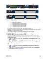
1
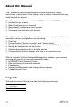
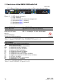
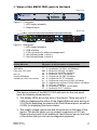
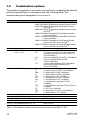
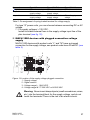
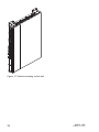
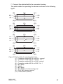
User Manual Installation Industrial ETHERNET Ruggedized Switch MACH 1000 Family USB V.24 LS DA LS 7 4 3 LS DA 8 12 11 R1 R2 FAULT LS MACH 1020 6 5 16 15 P RM StandBy DA LS DA LS DA 19 20 23 24 25 26 DA 9 10 13 14 17 18 21 22 7 8 11 12 15 16 19 20 23 24 21 22 25 26 19 20 23 24 21 22 25 26 MACH 1020 USB V.24 LS DA LS LS DA DA LS DA 1 4 3 P RM StandBy LS DA LS DA 2 R1 R2 FAULT MACH 1030 5 6 9 10 13 14 4 7 8 11 12 18 17 MACH 1030 USB V.24 1 3 16 15 P RM StandBy LS DA LS DA 2 R1 R2 FAULT MACH 1000 6 5 9 10 14 13 18 17 MACH 1032 22 USB V.24 LS DA LS DA 1 4 3 P RM StandBy LS 7 8 12 11 16 15 DA LS DA LS 19 20 23 24 21 22 25 26 DA 2 R1 R2 FAULT MACH 1000 5 6 9 10 14 13 17 P RM StandBy 1 3 5 7 R1 R2 FAULT 2 4 6 8 10 12 14 16 18 20 22 24 18 9 11 13 15 17 19 21 23 ETHERNET Service Port MACH 1132 MACH 1000 Release 02 10/10 Technical Support [email protected] The naming of copyrighted trademarks in this manual, even when not specially indicated, should not be taken to mean that these names may be considered as free in the sense of the trademark and tradename protection law and hence that they may be freely used by anyone. © 2010 Hirschmann Automation and Control GmbH Manuals and software are protected by copyright. All rights reserved. The copying, reproduction, translation, conversion into any electronic medium or machine scannable form is not permitted, either in whole or in part. An exception is the preparation of a backup copy of the software for your own use. For devices with embedded software, the end-user license agreement on the enclosed CD applies. The performance features described here are binding only if they have been expressly agreed when the contract was made. This document was produced by Hirschmann Automation and Control GmbH according to the best of the company's knowledge. Hirschmann reserves the right to change the contents of this document without prior notice. Hirschmann can give no guarantee in respect of the correctness or accuracy of the information in this document. Hirschmann can accept no responsibility for damages, resulting from the use of the network components or the associated operating software. In addition, we refer to the conditions of use specified in the license contract. You can get the latest version of this manual on the Internet at the Hirschmann product site (www.beldensolutions.com). Printed in Germany Hirschmann Automation and Control GmbH Stuttgarter Str. 45-51 72654 Neckartenzlingen Germany Tel.: +49 1805 141538 MACH 1000 039 687-002-02-1010 14.10.10 Contents Safety instructions 4 About this Manual 10 Legend 10 1 Device description 11 1.1 Description of the device variants 12 1.2 Combination options 18 2 Assembly and start-up 21 2.1 Installing the device 2.1.1 Unpacking and checking 2.1.2 Installing the SFP modules (optional) 2.1.3 Connecting the power unit connections for supply voltage and signal contact 2.1.4 Installing the device and grounding 2.1.5 Startup procedure 2.1.6 Connecting the data lines 21 21 21 2.2 Display elements 38 2.3 Basic set-up 41 2.4 Disassembling the device 43 3 Technical data 44 A Further Support 53 MACH 1000 Release 02 10/10 22 30 34 34 3 Safety instructions This documentation contains instructions which must be observed to ensure your own personal safety and to avoid damage to devices and machinery. Certified usage The device may only be employed for the purposes described in the catalog and technical description, and only in conjunction with external devices and components recommended or approved by the manufacturer. The product can only be operated correctly and safely if it is transported, stored, installed and assembled properly and correctly. Furthermore, it must be operated and serviced carefully. Supply voltage The supply voltage is electrically isolated from the housing. Use undamaged parts. The device does not contain any service components. Internal fuses are only triggered if there is a fault in the device. If the device is not functioning correctly, or if it is damaged, switch off the voltage supply and return the device to the plant for inspection. Only switch on the device when the housing is closed. Connect the protective conductor before you set up the other connections. When removing the connections, you remove the protective conductor last. Connect both protective conductors if your device is equipped with two power supply units. Make sure that the cross-section of the protective conductor cable is the same size as or bigger than the cross-section of the voltage supply cables. Only use connection cables that are permitted for the specified temperature range. Warning: Never insert sharp objects (small screwdrivers, wires, etc.) into the field connection terminals for the supply voltage, and do not touch the terminals! There is the risk of an electric shock. 4 MACH 1000 Release 02 10/10 Warning: – If the neutral conductor or the negative terminal of the supply voltage is not grounded – If you are using a DC voltage greater than 125 VDC for the supply voltage install a suitable input fuse. For power supply units with product code “G” or “M”, use a slowblow fuse with a nominal rating of 2.5 A for the voltage supply input. For power supply units with product code “C” or “L”, use a slowblow fuse with a nominal rating of 6.3 A. With AC power supply, use a cable cross-section of at least 0.75 mm² (North America: AWG 18) for the current conductor at the voltage input. With DC power supply, use a cable cross-section of at least 1.0 mm² (North America: AWG 16) for the current conductor at the voltage input. Relevant for North America: For use in Class 2 circuits. Only use copper wire/conductors of class 1, 60/75°C or 75°C. Warning: Only connect a supply voltage that corresponds to the type plate of your device. Power unit type “C” and “L”: 18 to 60 V DC Power unit type “G” and “M”: 77 to 300 V DC or 90 to 265 V AC Shielding ground The shielding ground of the connectable twisted pairs lines is connected to the front panel as a conductor. Beware of possible short circuits when connecting a cable section with conductive shielding braiding. Housing Only technicians authorized by the manufacturer are permitted to open the housing. Depending on the device variant, it is grounded via a separate spring-loaded terminal. This is located at the 1 or 2 power supply module(s) on the back of the device. via a ground connection on the front panel of the device. Make sure that the electrical installation meets local or nationally applicable safety regulations. The ventilation slots must not be covered so as to ensure free air circulation. The clearance to the ventilation slots of the housing must be at least 10 cm (3.94 in). Do not touch the housing during operation or shortly after switching off the device. Hot surfaces can cause injury. MACH 1000 Release 02 10/10 5 Warning! Never insert sharp objects (small screwdrivers, wires, etc.) into the inside of the product. There is the risk of an electric shock. The device must be installed in the horizontal or upright position, either in the switch cabinet or on the wall (see on page 30 “Installing the device and grounding”) The device is not intended for operation as a table unit. Operating the device in the maximum surrounding air temperature and stacking devices: When installing the device, make sure there is at least one free rack space (approx. 5 cm) above the device, because heat is discharged via the housing of the device. If you are operating the device in a 19" switch cabinet: install sliding/ mounting rails for holding the device (see on page 30 “Installing the device and grounding”). Warning: Only install the device in rooms / plants that are only accessible to trained maintenance personnel. If installed in a living area or office environment, the device must be operated exclusively in switch cabinets with fire protection characteristics in accordance with EN 60950-1. Warning: Never insert sharp objects (small screwdrivers, wires, etc.) into the field connection terminals for the supply voltage, and do not touch the terminals! There is the risk of an electric shock. Environment The device may only be operated at the specified surrounding air temperature (temperature of the surrounding air at a distance of up to 5 cm (1.97 in) from the device) and relative air humidity specified in the technical data. Install the device in a location where the climatic threshold values specified in the technical data will be observed. Use the device only in an environment within the contamination level specified in the technical data. Qualification requirements for personnel Qualified personnel as understood in this manual and the warning signs, are persons who are familiar with the setup, assembly, startup, and operation of this product and are appropriately qualified for their job. This includes, for example, those persons who have been: 6 MACH 1000 Release 02 10/10 trained or directed or authorized to switch on and off, to ground and to label power circuits and devices or systems in accordance with current safety engineering standards; trained or directed in the care and use of appropriate safety equipment in accordance with the current standards of safety engineering; trained in providing first aid. General safety instructions Electricity is used to operate this equipment. Comply with every detail of the safety requirements specified in the operating instructions regarding the voltages to apply (see page 4). Non-observance of these safety instructions can therefore cause material damage and/or serious injuries. Only appropriately qualified personnel should work on this device or in its vicinity. These personnel must be thoroughly familiar with all the warnings and maintenance procedures in accordance with this operating manual. The proper and safe operation of this device depends on proper handling during transport, proper storage and assembly, and conscientious operation and maintenance procedures. Never start operation with damaged components. Only use the devices in accordance with this manual. In particular, observe all warnings and safety-related information. Any work that may be required on the electrical installation may only be carried out by personnel trained for this purpose. Please note that products recommended as accessories may have characteristics that do not fully correspond to those of the corresponding product. This may limit their possible usage in the overall system. Note: LED or LASER components in compliance with IEC 60825-1 (2001): CLASS 1 LASER PRODUCT CLASS 1 LED PRODUCT MACH 1000 Release 02 10/10 7 Warning Laser light Do not look into the beam or view it directly with optical instruments (e.g. magnifying glass, microscope). Failure to observe this warning within a distance of 100 mm can endanger your sight. Light is emitted from the optical connections or from the ends of the optical fibers that are connected to them. Light Emitting Diode CLASS 2M, wave length 650 nm, power <2 mW, according to DIN EN 60825-1:2003-10. National and international safety regulations Make sure that the electrical installation meets local or nationally applicable safety regulations. CE marking The devices comply with the regulations contained in the following European directive(s): 2004/108/EG Directive of the European Parliament and the council for standardizing the regulations of member states with regard to electromagnetic compatibility. 2006/95/EG Directive of the European Parliament and the council for standardizing the regulations of member states with regard to electrical equipment to be used within specific voltage ranges. In accordance with the above-named EU directive(s), the EU conformity declaration will be at the disposal of the relevant authorities at the following address: Hirschmann Automation and Control GmbH Stuttgarter Str. 45-51 72654 Neckartenzlingen Tel.: +49 1805 141538 The product can be used in the industrial sector. Interference immunity: EN 61000-6-2:2005 Emitted interference: EN 55022:2006 + A1:2007 Class A Safety: EN 60950-1:2006 8 MACH 1000 Release 02 10/10 Warning! This is a class A device. This device can cause interference in living areas, and in this case the operator may be required to take appropriate measures. Warning! The assembly guidelines provided in these instructions must be strictly adhered to in order to observe the EMC threshold values. FCC note: This device complies with part 15 of FCC rules. Operation is subject to the following two conditions : (1) This device may not cause harmful interference; (2) this device must accept any interference received, including interference that may cause undesired operation. Appropriate testing has established that this device fulfills the requirements of a class A digital device in line with part 15 of the FCC regulations. These requirements are designed to provide sufficient protection against interference when the device is being used in a business environment. The device creates and uses high frequencies and can radiate same, and if it is not installed and used in accordance with this operating manual, it can cause radio transmission interference. The use of this device in a living area can also cause interference, and in this case the user is obliged to cover the costs of removing the interference. Recycling note After usage, this product must be disposed of properly as electronic waste, in accordance with the current disposal regulations of your county, state and country. MACH 1000 Release 02 10/10 9 About this Manual The “Installation” user manual contains a device description, safety instructions, a description of the display, and the other information that you need to install the device. The following manuals are available as PDF files on the CD-ROM supplied: Installation user manual Basic Configuration user manual Redundancy Configuration user manual Web-based Interface reference guide Command Line Interface user manual The HiVision Network Management Software provides you with additional options for smooth configuration and monitoring: Event log Configuration of “System Location” and “System Name” Configuration of the network address range and the SNMP parameters Saving the configuration on the device Simultaneous configuration of multiple devices Configuration of the port display color red for a connection error With the Industrial HiVision Network Management software, you increase your network security in industrial application areas: ETHERNET Early Warning System Easy monitoring of industrial networks Fast display Interface with diagnostic and configuration programs Low deployment cost Legend The symbols used in this manual have the following meanings: 10 Listing Work step Subheading MACH 1000 Release 02 10/10 1 Device description The Ruggedized Switch for Substations and Transportation MACH 1000 Family provides you with a wide range of Switch variants. You set up your own Switch according to your requirements regarding the number of ports, transmission speed, media type, connector type, temperature range, voltage range and software variant. The MACH 1000 devices are designed for the special requirements of industrial automation. They meet the relevant industry standards, provide very high operational reliability, even under extreme conditions, and also long-term reliability and flexibility. The devices work without a fan. If required, the devices are PoE-capable. For devices without PoE, the voltage supply can be redundant if required. The Switches are mounted in the switch cabinet by means of brackets, or vertically on the wall. The HIPER-Ring redundancy concept enables you to quickly carry out a reconfiguration, and also a simple configuration with only one additional connection. Diagnosis displays and the display of the operating parameters provide a quick overview. It can be easily managed via a Web browser, via Telnet, with a management software product (such as HiVision) or locally on the switch (V.24 interface). The device allows you to set up switched industrial ETHERNET networks that conform to the IEEE 802.3 and 802.3u standards using copper wires or optical fibers in a line or ring structure. You can connect terminal devices and other infrastructure components via twisted pair cables, multi-mode F/O and single-mode F/O. The twisted pair ports support autocrossing, autonegotiation and autopolarity. Depending on the software you choose, the devices provide you with a large range of functions: Redundancy functions (Rapid Spanning Tree, Redundant Ring Structure, HIPER-Ring, Redundant Coupling, Link Aggregation, for devices without PoE Redundant Power Supply) Protection from unauthorized access Synchronized system time in the network Network load control Operation diagnosis Diagnostics (hardware self-testing) Reset Priority VLAN Topology Discovery Web-based Interface Command Line Interface CLI MACH 1000 Release 02 10/10 11 SNMP 802.1x port authentication Real Time Clock (Professional software variant) The addition, to the MACH 1000 Ruggedized Switch series, of the switches of the Open Rail range, the MICE range, the backbone switches of the MACH 3000 and MACH 4000 ranges, the BAT wireless transmission system, the EAGLE security system, and products for the LION control room, provides continuous communication across all levels of the company. 1.1 Description of the device variants The devices differ with regard to the range of software functions, the number of interfaces, and the media type for connecting segments. The MAR1020-..., MAR1022-..., MAR1120-... and MAR1122-... device variants are MACH 1000 Ruggedized Switches without Gigabit ports and, depending on the requirements, a selectable number (up to 24) of Fast Ethernet ports (10/100 Mbit/s). You can choose the media for the Fast Ethernet ports 1 to 24 in pairs. The MAR1120-... and MAR1122-... devices have an additional Fast Ethernet port on the front of the device that you can use for diagnosis purposes. The MAR1022-... devices support PoE in accordance with IEEE 802.3af. The PoE ports are the Fast Ethernet ports 1 to 4. In the MAR1120-... devices, all the cable outlets are at the back, i.e. the ports are on the back of the device. The MAR1122-... devices support PoE in accordance with IEEE 802.3af. The PoE ports are the Fast Ethernet ports 1 to 4. All the cable outlets are at the back, i.e. the ports are on the back of the device. The MAR1030-..., MAR1032-..., MAR1130-... and MAR1132-... device variants are MACH 1000 Ruggedized Switches with 2 or 4 Gigabit ports (10/100/1000 Mbit/s) and, depending on the requirements, a selectable number (up to 24) of Fast Ethernet ports (10/100 Mbit/s). You can choose the media for the Fast Ethernet ports 1 to 24 in pairs. In device variants with 2 Gigabit Ethernet ports, these ports are combo ports (2 x SFP slot: 100/1000 Mbit/s, alternatively: 2 x twisted pair RJ45 socket: 10/100/1000 Mbit/s). In device variants with 4 Gigabit Ethernet ports, these can be optionally SFP slots (2 x 2 slots), 12 MACH 1000 Release 02 10/10 - twisted pair RJ45 sockets (2 x 2 sockets) or - 2 x SFP slots plus 2 x twisted pair RJ45 sockets. The MAR1130-... and MAR1132-... devices have an additional Fast Ethernet port on the front of the device that you can use for diagnosis purposes. The MAR1032-... devices support PoE (Power over Ethernet) in accordance with IEEE 802.3af. The PoE ports are the Fast Ethernet ports 1 to 4. In the MAR1130-... devices, all the cable outlets are at the back, i.e. the ports are on the back of the device. The MAR1132-... devices support PoE (Power over Ethernet) in accordance with IEEE 802.3af. The PoE ports are the Fast Ethernet ports 1 to 4. In these devices, all the cable outlets are at the back, i.e. the ports are on the back of the device. The devices also provide you with the following options for selecting the variant you desire: Temperature range: Standard 0 °C to +60 °C Extended -40 °C to +85 °C Extended -40 °C to +85 °C, conformal coating Voltage range for power supply unit 1 and the optional power supply unit 2: 18 VDC to 60 VDC 77 VDC to 300 VDC or 90 VAC to 265 VAC The voltage supply connection can be a terminal or plugged connection, as desired. In devices with PoE, power supply unit 2 is the PoE power supply unit. You can choose the connections to power supply unit 1. Software variant: Professional The devices comply with the specifications of the ISO/IEC standards 8802-3u 100BASE-TX/-1000BASE-T, 8802-3 100BASE-FX and 8802-3 1000BASE-SX/LX. MACH 1000 Release 02 10/10 13 Front view of the MACH 1000 with 2 Gigabit ports 1 2 3 4 2 1 1 USB MACH 1000 5 V.24 LS DA LS 5 6 9 8 11 14 13 10 17 18 21 22 19 20 23 24 DA 1 3 4 7 12 16 15 P RM StandBy LS DA LS DA 2 R1 R2 FAULT MACH 1000 2 5 6 3 4 9 7 10 8 13 11 14 17 15 12 18 21 22 25 26 16 19 20 23 24 Figure 1: 1 - LED display elements 2 - USB interface 3 - V.24 connection for external management 4 - See following table, column 1 5 - See following table, column 2 Gigabit ETHERNET Fast ETHERNET GE ports 1 and 2 (combo ports) FE ports 1 to 24, free choice of connections 99: Module position empty 100/1000 Mbit/s TT: 2 * twisted pair TX, RJ45, 10/100 Mbit/s Fiber optic, SFP slots MM: 2 * Multimode FX DSC 100 Mbit/s JJ: 2 * Multimode FX MTRJ 100 Mbit/s NN: 2 * Multimode FX ST 100 Mbit/s Alternative connections: VV: 2 * Singlemode FX DSC 100 Mbit/s 10/100/1000 Mbit/s UU: 2 * Singlemode FX ST 100 Mbit/s Twisted pair, RJ45 connections LL: 2 * Singlemode Long Haul FX DSC 100 Mbit/s GG: 2 * Singlemode Long Haul FX DSC 200 km 100 Mbit/s ZZ: 2 * SFP slot 100 Mbit/s RR: 2 * twisted pair TX, M12, 10/100 Mbit/s FF: 2 * Multimode FL ST 10 Mbit/s Front view of the MACH 1000 with 4 Gigabit ports (SFP) 1 2 3 4 1 USB MACH 1000 5 3 1 2 3 4 5 6 9 8 11 14 13 10 17 18 21 22 19 20 23 24 V.24 1 7 12 P RM StandBy 16 15 LS DA LS DA 2 R1 R2 FAULT MACH 1000 2 4 5 6 3 4 9 7 10 8 13 11 14 12 17 15 18 21 22 25 26 16 19 20 23 24 Figure 2: 1 - LED display elements 2 - USB interface 3 - V.24 connection for external management 4 - See following table, column 1 5 - See following table, column 2 14 MACH 1000 Release 02 10/10 Gigabit ETHERNET GE ports 1 to 4 Fast ETHERNET FE ports 1 to 24, free choice of connections 99: Module position empty TT: 2 * twisted pair TX, RJ45, 10/100 Mbit/s MM: 2 * Multimode FX DSC 100 Mbit/s JJ: 2 * Multimode FX MTRJ 100 Mbit/s NN: 2 * Multimode FX ST 100 Mbit/s VV: 2 * Singlemode FX DSC 100 Mbit/s UU: 2 * Singlemode FX ST 100 Mbit/s LL: 2 * Singlemode Long Haul FX DSC 100 Mbit/s GG: 2 * Singlemode Long Haul FX DSC 200 km 100 Mbit/s ZZ: 2 * SFP slot 100 Mbit/s RR: 2 * twisted pair TX, M12, 10/100 Mbit/s FF: 2 * Multimode FL ST 10 Mbit/s 1000 Mbit/s Fiber optic, SFP slots Front view of the MACH 1000 with 4 Gigabit ports (2 x SFP and 2 x RJ45) 1 2 3 4 1 USB MACH 1000 5 3 1 2 3 4 5 6 9 8 11 14 13 10 17 18 21 22 19 20 23 24 V.24 1 7 12 P RM StandBy 16 15 LS DA LS DA 2 R1 R2 FAULT MACH 1000 2 4 5 6 3 4 9 7 10 8 13 11 14 12 17 15 18 21 22 25 26 16 19 20 23 24 Figure 3: 1 - LED display elements 2 - USB interface 3 - V.24 connection for external management 4 - See following table, column 1 5 - See following table, column 2 Gigabit ETHERNET GE ports 1 to 4 1000 Mbit/s Fiber optic, SFP slots And / or: 10/100/1000 Mbit/s Twisted pair, RJ45 connections MACH 1000 Release 02 10/10 Fast ETHERNET FE ports 1 to 24, free choice of connections 99: Module position empty TT: 2 * twisted pair TX, RJ45, 10/100 Mbit/s MM: 2 * Multimode FX DSC 100 Mbit/s JJ: 2 * Multimode FX MTRJ 100 Mbit/s NN: 2 * Multimode FX ST 100 Mbit/s VV: 2 * Singlemode FX DSC 100 Mbit/s UU: 2 * Singlemode FX ST 100 Mbit/s LL: 2 * Singlemode Long Haul FX DSC 100 Mbit/s GG: 2 * Singlemode Long Haul FX DSC 200 km 100 Mbit/s ZZ: 2 * SFP slot 100 Mbit/s RR: 2 * twisted pair TX, M12, 10/100 Mbit/s FF: 2 * Multimode FL ST 10 Mbit/s 15 Front view of the MACH 1000 with PoE 1 2 3 4 5 V.24 2 1 1 USB LS MACH 1000 6 DA LS DA LS 5 6 9 8 11 14 13 10 17 18 21 22 19 20 23 24 DA 1 LS 7 4 3 P RM StandBy 12 DA 16 15 LS DA LS DA 2 R1 R2 FAULT MACH 1000 2 5 6 9 3 4 7 10 8 13 11 14 12 17 15 18 21 22 25 26 16 19 20 23 24 Figure 4: 1 - LED display elements 2 - USB interface 3 - V.24 connection for external management 4 - See below table 1, column 1 5 - See below table 1, column 2 6 - See below table 2 Gigabit ETHERNET Up to 4 GE ports 1000 Mbit/s Fiber optic, SFP slots Fast ETHERNET FE ports 1 to 4, Power over Ethernet TT: 2 * twisted pair TX, RJ45, 10/100 Mbit/s RR: 2 * twisted pair TX, M12, 10/100 Mbit/s And / or: 10/100/1000 Mbit/s Twisted pair, RJ45 connections P Power over ETHERNET Table 1: Gigabit ETHERNET, Fast ETHERNET FE ports 1 to 4 Fast ETHERNET FE ports 5 to 24, free choice of connections 99: Module position empty TT: 2 * twisted pair TX, RJ45, 10/100 Mbit/s MM: 2 * Multimode FX DSC 100 Mbit/s JJ: 2 * Multimode FX MTRJ 100 Mbit/s NN: 2 * Multimode FX ST 100 Mbit/s VV: 2 * Singlemode FX DSC 100 Mbit/s UU: 2 * Singlemode FX ST 100 Mbit/s LL: 2 * Singlemode Long Haul FX DSC 100 Mbit/s GG: 2 * Singlemode Long Haul FX DSC 200 km 100 Mbit/s ZZ: 2 * SFP slot 100 Mbit/s RR: 2 * twisted pair TX, M12, 10/100 Mbit/s FF: 2 * Multimode FL ST 10 Mbit/s Table 2: Fast ETHERNET, FE ports 5 to 24 16 MACH 1000 Release 02 10/10 Views of the MACH 1000, ports in the back 1 MACH 1000 2 P RM StandBy 1 3 5 7 R1 R2 FAULT 2 4 6 8 10 12 14 16 18 20 22 24 9 11 13 15 17 19 21 23 ETHERNET Service Port Figure 5: Front panel: 1 - LED display elements 2 - Diagnosis port 1 2 3 4 V.24 2 1 1 USB MACH 1000 5 LS DA LS 5 6 9 8 11 14 13 10 17 18 21 22 DA 1 4 3 P RM StandBy LS 7 12 DA 16 15 LS DA LS 19 20 24 23 -/N +/L DA 2 R1 R2 FAULT MACH 1000 2 5 6 3 4 9 7 10 8 13 11 14 12 17 15 18 16 21 19 22 25 26 20 23 24 Figure 6: Rear panel: 1 - LED display elements 2 - USB interface 3 - V.24 connection for external management 4 - See following table, column 1 5 - See following table, column 2 Gigabit ETHERNET Up to 4 GE ports 1000 Mbit/s Fiber optic, SFP slots And / or: 10/100/1000 Mbit/s Twisted pair, RJ45 connections Fast ETHERNET FE ports 1 to 20, free choice of connections 99: Module position empty TT: 2 * twisted pair TX, RJ45, 10/100 Mbit/s MM: 2 * Multimode FX DSC 100 Mbit/s JJ: 2 * Multimode FX MTRJ 100 Mbit/s NN: 2 * Multimode FX ST 100 Mbit/s VV: 2 * Singlemode FX DSC 100 Mbit/s UU: 2 * Singlemode FX ST 100 Mbit/s LL: 2 * Singlemode Long Haul FX DSC 100 Mbit/s GG: 2 * Singlemode Long Haul FX DSC 200 km 100 Mbit/s ZZ: 2 * SFP slot 100 Mbit/s RR: 2 * twisted pair TX, M12, 10/100 Mbit/s FF: 2 * Multimode FL ST 10 Mbit/s The device variants of the MACH 1000 with ports on the rear panel have the following characteristics: The display LEDs are on the front of the device. There are up to 4 LEDs for displaying the status of the Gigabit Ethernet ports and up to 21 LEDs for displaying the status of the Fast Ethernet ports, as well as 6 LEDs for displaying the device status. The supply voltage connection and the ports are on the back of the device. The device allows you to connect a maximum of 20 Fast Ethernet ports as well as an additional Fast Ethernet port on the front of the device that you can use for diagnosis purposes. MACH 1000 Release 02 10/10 17 1.2 Combination options The product designation of your device is made from combining the desired product characteristics in accordance with the following table. The corresponding short designation is in column 3. Item 1 to 7 Characteristic Product Ident. MAR1020 MAR1030 MAR1022 MAR1032 MAR1120 MAR1130 MAR1122 MAR1132 8 9 to 10 - (hyphen) 10/100/1000 Mbit/s ports 1+2 or 1 to 4 99 CC 4O 4T OT 11 to 12 10/100 Mbit/s ports 1+2 a) 99 TT MM JJ NN VV UU LL GG ZZ RR FF b 13 to 14 15 to 16 17 to 18 19 to 20 21 to 22 10/100 Mbit/s ports 3 + 4 10/100 Mbit/s ports 5 + 6 10/100 Mbit/s ports 7 + 8 10/100 Mbit/s ports 9 + 10 10/100 Mbit/s ports 11 + 12 Property MACH Ruggedized Fast Ethernet Switch MACH Ruggedized Gigabit Ethernet Switch MACH Ruggedized Fast Ethernet Switch with PoE ab MACH Ruggedized Gigabit Ethernet Switch with PoE ab MACH Ruggedized Fast Ethernet Switch, ports on the back MACH Ruggedized Gigabit Ethernet Switch, ports on the back MACH Ruggedized Fast Ethernet Switch, ports on the back and with PoE ab MACH Ruggedized Gigabit Ethernet Switch, ports on the back and with PoE ab Not present (in MAR1020) 2 * combo port (SFP slot: 100/1000 Mbit/s, alternatively twisted pair RJ45 socket: 10/ 100/1000 Mbit/s) 2*2 ports Gigabit Ethernet SFP, 1000 Mbit/s 2*2 ports Gigabit Ethernet RJ45 10/100/1000 Mbit/s 2 ports Gigabit Ethernet SFP 1000 Mbit/s plus 2 ports Gigabit Ethernet RJ45 10/100/1000 Mbit/s Module position empty 2 * twisted pair TX, RJ45, 10/100 Mbit/s 2 * Multimode FX DSC 100 Mbit/s 2 * Multimode FX MTRJ 100 Mbit/s 2 * Multimode FX ST 100 Mbit/s 2 * Singlemode FX DSC 100 Mbit/s 2 * Singlemode FX ST 100 Mbit/s 2 * Singlemode Long Haul FX DSC 100 Mbit/s 2 * Singlemode Long Haul FX DSC 200 km 100 Mbit/s 2 * SFP slot 100 Mbit/s 2 * twisted pair TX, M12, 10/100 Mbit/s 2 * Multimode FL ST 10 Mbit/s See 11 to 12 See 11 to 12 See 11 to 12 See 11 to 12 See 11 to 12 Table 3: Combination options for the device variants of the MACH 1000 18 MACH 1000 Release 02 10/10 Item 23 to 24 25 to 26 27 to 28 29 to 30 31 to 32 33 to 34 35 Characteristic Ident. 10/100 Mbit/s ports 13 + 14 10/100 Mbit/s ports 15 + 16 10/100 Mbit/s ports 17 + 18 10/100 Mbit/s ports 19 + 20 10/100 Mbit/s ports 21 + 22 10/100 Mbit/s ports 23 + 24 Temperature range S U F 36 Voltage range power supply unit 1 C G L M 37 Voltage range power supply unit 2 or PoE power supply unit 9 C G L M 38 Certifications H T 39 Software variant P Property See 11 to 12 See 11 to 12 See 11 to 12 See 11 to 12 See 11 to 12 See 11 to 12 Standard 0 °C to +60 °C Extended -40 °C to +85 °C Extended -40 °C to +85 °C, conformal coating 18 VDC to 60 VDC terminal connection 77 VDC to 300 VDC or 90 VAC to 265 VAC terminal connection 18 VDC to 60 VDC plugged connection 77 VDC to 300 VDC or 90 VAC to 265 VAC plugged connection Not present 18 VDC to 60 VDC terminal connection 77 VDC to 300 VDC or 90 VAC to 265 VAC terminal connection 18 VDC to 60 VDC plugged connection 77 VDC to 300 VDC or 90 VAC to 265 VAC plugged connection CE, UL 508, GL, IEC 61850, IEEE 1613 Substation, EN 50121-4 Railway (along track) CE, UL 508, EN 50121-4 Railway (along track), EN 50155 Railway (train) c Professional Table 3: Combination options for the device variants of the MACH 1000 a. In device variants with PoE (Power over Ethernet), the first four ports can be twisted pair TX RJ45 10/100 Mbit/s (short designation TT) or twisted pair TX M12 10/100 Mbit/s (short designation RR), as desired. The remaining ports can be selected freely from the table. Power supply unit 2 is a PoE power supply unit (incoming voltage range, item 37: “G” or “M”). You can choose the connections to power supply unit 1. b. Devices with PoE or with FL ports: No „T“ certification (EN 50155 Railway (train)) available. c. Nominal voltage on power supply type G and M: 110 VDC; on power supply type C and L: 36 VDC. MACH 1000 Release 02 10/10 19 Example of MACH 1000 product designation MAR1030- CC MACH Ruggedized Switch with Gigabit ports TT MM JJ NN VV UU LL GG ZZ TT 99 99 F C 2 * combo port (SFP slot: 100/1000 Mbit/s, alternatively twisted pair RJ45 socket: 10/100/ 1000 Mbit/s) 10/100 Mbit/s ports 1 + 2: 2 * twisted pair TX, RJ45, 10/100 Mbit/s G H 10/100 Mbit/s ports 3 + 4: 2 * Multimode FX DSC 100 Mbit/s 10/100 Mbit/s ports 5 + 6: 10/100 Mbit/s ports 7 + 8: 2 * Multimode FX MTRJ 100 Mbit/s 2 * Multimode FX ST 100 Mbit/s 10/100 Mbit/s ports 9 + 10: 2 * Singlemode FX DSC 100 Mbit/s 10/100 Mbit/s ports 11 + 12: 2 * Singlemode FX ST 100 Mbit/s 10/100 Mbit/s ports 13 + 14: 2 * Singlemode Long Haul FX DSC 100 Mbit/s 10/100 Mbit/s ports 15 + 16: 2 * Singlemode Long Haul FX DSC 200 km 100 Mbit/s 10/100 Mbit/s ports 17 + 18: 2 * SFP slot 100 Mbit/s 10/100 Mbit/s ports 19 + 20: 2 * twisted pair TX, RJ45, 10/100 Mbit/s 10/100 Mbit/s ports 21 + 22: Module position empty 10/100 Mbit/s ports 23 + 24: Module position empty Temperature range extended: Voltage range, power supply unit 1: Voltage range, power supply unit 2: Certifications: -40 °C to +85 °C, conformal coating 18 VDC to 60 VDC P Software variant: 77 VDC to 300 VDC or 90 VAC to 265 VAC CE, UL 508, GL, IEC 61850, IEEE 1613 Substation, EN 50121-4 Railway (along track) Professional Table 4: Example of the product designation of a MACH 1000 with 2 Gigabit ports: MACH 1030- CC TT MM JJ NN VV UU LL GG ZZ TT 99 99 F C G H P 20 MACH 1000 Release 02 10/10 2 Assembly and start-up The devices have been developed for practical application in a harsh industrial environment. The installation process is correspondingly simple. On delivery, the device is ready for operation. The following procedure has been proven to be successful for the assembly of the device: Unpacking and checking Installing the SFP modules (optional) Connecting the power unit connections for supply voltage and signal contact Installing the device and grounding Startup Connecting the data lines 2.1 Installing the device 2.1.1 Unpacking and checking Check that the contents of the package are complete (see page 49 “Scope of delivery”). Check the individual parts for transport damage. 2.1.2 Installing the SFP modules (optional) 1 2 Figure 7: 1 - Fast EHTERNET fiber optic SFP module 2 - Gigabit ETHERNET fiber optic SFP module Before attaching an SFP module, first remove the protective cap over the socket. Push the SFP module with the lock closed into the socket until it latches audibly in place. Note: Only use Hirschmann SFP modules (see page 50 “Accessories”). MACH 1000 Release 02 10/10 21 2.1.3 Connecting the power unit connections for supply voltage and signal contact Connect the power supply and signal lines. Note: Note the safety instructions (see on page 4 “Supply voltage”) and only connect a supply voltage that corresponds to the type plate of your device. Make sure that the contact load capability of the signal contact is not exceeded (see on page 44 “Technical data”). Connecting the supply voltage Connecting the supply voltage: For device types with power units of the type “C” or “G” (voltage supply terminal connection) via a 3-pin spring-loaded terminal, the signal contact is connected via a 2-pin spring-loaded terminal to the power units (power unit 1 and/or power unit 2, depending on the device variant) on the back of the MACH1000 device. For device types with power units of the type “L” or “M” (voltage supply plugged connection) via a 3-pin terminal block with screw locking, the signal contact is connected via a 2-pin terminal block (1 or 2 blocks, depending on the device variant) on the back of the MACH1000 device. 1 2 3 1 Relay 1 Relay 2 N L N L 1 2 3 3 4 4 5 1 2 3 4 5 Figure 8: MACH 1000, back of device, terminal voltage connection 1 - Supply voltage 2 - Power unit 2 (optional) 3 - Signal contact 4 - Power unit 1 22 MACH 1000 Release 02 10/10 1 USB V.24 LS DA LS 2 DA 1 P RM StandBy LS 7 4 3 8 12 11 DA 16 15 LS DA LS 19 20 24 23 -/N +/L DA 2 R1 R2 FAULT MACH 1000 4 5 6 9 10 14 13 3 17 18 21 22 25 4 26 3 Relay 2 N L -/N +/L 5 1 2 3 4 5 6 Relay 2 N L -/N +/L 1 2 3 4 5 Figure 9: MACH 1000 device variants (back of device), plugged voltage connection 1 - Power unit 1 2 - Power unit 2 (optional) 3 - 2 Terminal blocks for signal contact 4 - 2 Terminal blocks for supply voltage 5 - 1 Terminal block for supply voltage 6 - 1 Terminal block for signal contact For device variants without PoE: The supply voltage in MACH 1000 device types can be connected redundantly with two power units. Both inputs are uncoupled. The supply voltage is electrically isolated from the housing. MACH 1000 devices without PoE MACH 1000 device variants without PoE (Power over Ethernet) are, depending on the device type, equipped with one or two power units of the following type: Type “C” (18 VDC to 60 VDC, see product code items 36 and 37 in table 3 and/or Type “G” (77 VDC to 300 VDC or 90 VAC to 265 VAC, see product code items 36 and 37 in table 3 or Type “L” (18 VDC to 60 VDC, see product code items 36 and 37 in table 3 and/or Type “M” (77 VDC to 300 VDC or 90 VAC to 265 VAC, see product code items 36 and 37 in table 3. MACH 1000 Release 02 10/10 23 Note: For device variants without PoE: For device variants with two power units, if there is non-redundant voltage supply, the device reports the failure of one supply voltage. You can prevent this message by applying the supply voltage via both inputs, or by changing the configuration in the Management. MACH 1000 devices with PoE The MACH 1000 device variants MAR1022-..., MAR1032-..., MAR1132-... and MAR 1132-... support Power over Ethernet (PoE) in accordance with IEEE 802.3af. They allow the connection and remote supply of, for example, IP telephones (Voice over IP), webcams, sensors, printer servers and WLAN access points via 10BASE-T/100BASE-TX. With PoE, these terminal devices are powered by the twisted-pair cable. The MACH 1000 devices with PoE have 2*2 twisted pair ports TX 10/100 Mbit/s, depending on the device variant, as RJ45 or M12 sockets for connecting network segments or PoE terminal devices (PD, Powered Device) for all IEEE802.3af classes up to a maximum power output of 15.4 W. The current is supplied on wire pairs transmitting the signal; the individual ports are not electrically insulated from each other. The following conditions are met in accordance with IEEE 802.3af: Endpoint PSE Alternative A MACH 1000 device variants without PoE (Power over Ethernet) are equipped with two power units. Power unit 2 is a PoE power unit, see product code item 37 in table 3. You can choose the connections to power unit 1, see product code item 36 in table 3. MACH 1000 devices with terminal connection voltage supply MACH 1000 devices with product code “C” and “G” have a terminal connection for the supply voltage, see product code items 36 and 37 in table 3. Warning: Never insert sharp objects (small screwdrivers, wires, etc.) into the field connection terminals for the supply voltage, and do not touch the terminals! There is the risk of an electric shock. 24 MACH 1000 Release 02 10/10 Note: Observe the permitted voltage ranges for devices with type „T“ certifications (EN 50155 Railway (train), see product code item 38 in table 3). Power supply type G and M: nominal voltage 110 VDC Power supply type C and L: nominal voltage 36 VDC To insert the cable, you open the terminal lock by positioning the screwdriver as illustrated below and pressing on the lever. -/N +/L 1 2 3 1 2 Figure 10: Connecting the supply voltage via the 3-pin spring-loaded terminal 1 - Field connection terminal for supply voltage 2 - Terminal lock First connect the protective conductor to the protective conductor terminal. Connect the supply voltage via the 3-pin spring-loaded terminal. Pay attention to the +/L and -/N connections. If the neutral conductor or the minus terminal of the supply voltage is not grounded, install a suitable fuse in the input line. MACH 1000 Release 02 10/10 25 1 2 Relay - + 1 2 3 - 4 5 + Figure 11: Back of MACH 1000 device with power unit “C”, DC voltage (18...60 VDC) Connecting 1 - Supply voltage 2 - Signal contact 1 2 Relay -/N +/L 1 2 3 4 5 G 1 3 2 Relay -/N +/L 1 2 3 - 4 5 + Figure 12: Back of MACH 1000 device with power unit “G”, AC voltage 90-265 VAC (top image) or DC voltage 77-300 VDC (bottom image) Connecting 1 - Supply voltage 2 - Signal contact 3 - External fuse for supply voltages > 125 VDC 26 MACH 1000 Release 02 10/10 Connection , pin 1 -/N, pin 2 Type “C” Protective conductor Minus terminal of the supply voltage Plus terminal of the supply voltage +/L, pin 3 Type “G” VDC Protective conductor Minus terminal of the supply voltage Plus terminal of the supply voltage Type “G” VAC Protective conductor Neutral conductor “Phase” supply voltage Table 5: Pin assignment of spring-loaded terminal for voltage supply For type “G” power units, you can choose between connecting DC or AC voltage. For supply voltages > 125 VDC: Install a suitable external fuse in the supply voltage input line of the plus terminal (see fig. 12). MACH 1000 devices with plugged connection voltage supply MACH 1000 devices with product code “L” and “M” have a plugged connection for the supply voltage, see product code items 36 and 37 (see table 3). 1 2 3 -/N +/L 1 4 2 Figure 13: Location of the supply voltage plugged connection 1 - Supply voltage 2 - Signal contact 3 - Voltage range L: 18-60 VDC 4 - Voltage range M: 77-300 VDC or 90-265 VAC Warning: Never insert sharp objects (small screwdrivers, wires, etc.) into the terminal block for the supply voltage, and do not touch the terminals! There is the risk of an electric shock. MACH 1000 Release 02 10/10 27 Note: Note the safety instructions (see on page 4 “Supply voltage”) and only connect a supply voltage that corresponds to the type plate of your device. Make sure that the contact load capability of the signal contact is not exceeded (see on page 44 “Technical data”). Note: Observe the permitted voltage ranges for devices with type „T“ certifications (EN 50155 Railway (train), see product code item 38 in table 3). Power supply type G and M: nominal voltage 110 VDC Power supply type C and L: nominal voltage 36 VDC Note: Relevant for North America: The tightening torque of the terminal block screws is 3 lb in. (0.34 Nm). Pull the terminal block(s) off the switch and connect the voltage supply lines as follows: First connect the protective conductor to the protective conductor terminal. Connect the supply voltage via the 3-pin terminal block. Pay attention to the +/L and -/N connections. If the neutral conductor or the minus terminal of the supply voltage is not grounded, install a suitable fuse in the input line. 1 2 Relay Figure 14: Back of MACH 1000 device with power unit “L”, DC voltage (18...60 VDC) Connecting 1 - Supply voltage 2 - Signal contact 28 MACH 1000 Release 02 10/10 1 -/N +/L 1 2 3 Relay 2 -/N +/L Relay G Figure 15: Back of MACH 1000 device with power unit “M”, AC voltage 90-265 VAC (right image) or DC voltage 77-300 VDC (left image) Connecting 1 - Supply voltage 2 - Signal contact 3 - External fuse for supply voltages > 125 VDC Connection , pin 1 -/N, pin 2 +/L, pin 3 Type “L” Protective conductor Minus terminal of the supply voltage Plus terminal of the supply voltage Type “M” VDC Protective conductor Minus terminal of the supply voltage Plus terminal of the supply voltage Type “M” VAC Protective conductor Neutral conductor “Phase” supply voltage Table 6: Pin assignment of spring-loaded terminal for voltage supply For type “M” power units, you can choose between connecting DC or AC voltage. For supply voltages > 125 VDC: Install a suitable external fuse in the supply voltage input line of the plus terminal (see fig. 12). Note: The terminal blocks for devices with power unit type “M” (type “L”) are coded to prevent them from being accidently connected to devices with power unit type “L” (type “M”). Connecting the PoE supply voltage (optional) The devices connected are supplied with PoE voltage (48 V DC safety low voltage) via an internal power supply unit. The twisted-pair cables at Fast Ethernet ports 1 to 4 of the device are supplied with PoE voltage via the wire pairs transmitting the signal (phantom voltage) for both RJ45 and M12. “FAULT” signal contact Depending on the MACH 1000 device variant (equipped with one or two power units), you have either one or two signal contacts. MACH 1000 Release 02 10/10 29 The signal contact monitors proper functioning of the device, thus enabling remote diagnostics. You can specify the type of function monitoring in the Management. Pin assignment: for MACH 1000 devices – with terminal voltage supply (see fig. 11), (see fig. 12) – with plugged voltage supply (see fig. 14), (see fig. 15) You can also use the Management to switch the signal contact manually and thus control external devices. A break in contact is used to report the following conditions via the potential-free signal contact (relay contact, closed circuit): The failure of at least one supply voltage. A continuous malfunction in the device. The loss of connection at at least one port. The report of the link status can be masked by the Management for each port. In the delivery state, link status monitoring is deactivated. The loss of ring redundancy reserve. A detected error during the self-test. Incorrect configuration of the HIPER-Ring or ring coupling. Permitted temperature range exceeded/not reached. The following condition is also reported in RM mode: Ring redundancy reserve is available. On delivery, there is no ring redundancy monitoring. Note: You can use the signal contact functions when the voltage supply is connected. If there is redundant voltage supply, but this is turned off, there is a contact interruption at the corresponding signal contact. 2.1.4 Installing the device and grounding Note: The shielding ground of the connectable industrial twisted pair lines is connected to the front panel as a conductor. Mounting in a 19“ rack The devices are designed to be mounted in a 19" rack. Make sure there is sufficient ventilation. If necessary, provide a fan for the 19" rack. This will prevent the basic devices from overheating. Measure the depth of the 19" rack so as to allow the main cable, and any power supply cables, to be fitted from the back, and the data cables to be fitted from the front. If you are operating the device in a 19" switch cabinet, you must install sliding/mounting rails (not included in the delivery) to hold the weight of the device. 30 MACH 1000 Release 02 10/10 Warning! If the device is installed in a 19" switch cabinet without sliding/ mounting rails, increased vibration can cause damage to the device and/or its modules. For more information on sliding/mounting rails and how to install them, please contact your switch cabinet manufacturer. Install the sliding/mounting rails in the 19" switch cabinet as instructed by the manufacturer, and make sure the device is resting on both rails. On delivery, two brackets are attached to the sides of the device (see figure below). Fasten the device by screwing the brackets to the switch cabinet. USB V.24 LS DA LS LS DA DA LS DA 1 3 4 7 8 11 12 P RM StandBy 16 15 LS DA LS 19 20 23 21 22 25 24 26 DA 2 R1 R2 FAULT MACH 1000 5 6 9 10 13 14 17 18 MACH 1000 Figure 16: Mounting in the switch cabinet Warning! When installing the device, make sure the ventilation slots remain unobstructed, as otherwise the device can overheat and be damaged. Note: Fasten the device with two additional brackets at the back of the switch cabinet when operating it in environments with strong vibrations (see on page 50 “Accessories”, not included in the delivery). Vertical mounting on the wall Use the pre-mounted brackets included in the delivery as shown in the following figure (see fig. 17). Attach two additional brackets to the device (see on page 50 “Accessories”, not included in the delivery) as shown in the following figure (see fig. 17). Fasten the device by screwing the brackets to the wall. Warning! When installing the device, make sure the ventilation slots remain unobstructed, as otherwise the device can overheat and be damaged. Note: The shielding ground of the connectable industrial twisted pair lines is connected to the front panel as a conductor. MACH 1000 Release 02 10/10 31 Figure 17: Vertical mounting on the wall 32 MACH 1000 Release 02 10/10 53,2 31,75 313,5 218,25 31,75 482,6 444 465,9 44,2 31,8 44 342 352,5 482,6 465,9 Figure 18: MACH 1000, dimensions of device variants MACH 1000 Release 02 10/10 33 Grounding the device The device is grounded as follows: for MACH 1000 devices with terminal connection voltage supply via a separate spring-loaded terminal. This is located at the 1 or 2 power supply modules on the back of the device, at pin 1 (see fig. 11 and fig. 12). for MACH 1000 devices with plugged connection voltage supply: via a ground connection on the front panel of the device (see fig. 13). Connect the protective conductor before you set up the other connections. When removing the connections, you remove the protective conductor last. Connect both protective conductors if your device is equipped with two power supply units. 2.1.5 Startup procedure When you connect the supply voltage, you start up the device. 2.1.6 Connecting the data lines You can connect terminal devices and other segments at the ports of the device via twisted pair cables or F/O cables. Install the data lines according to your requirements. Note: To optimize the data flow, connect the main data traffic to ports 1 and 4. 10/100 Mbit/s twisted pair connection 10/100 Mbit/s ports (RJ45 socket) enable the connection of terminal devices or independent network segments according to the IEEE 802.3 100BASE-TX and 10BASE-T standard. These ports support: Autonegotiation Autopolarity Autocrossing (if autonegotiation is activated) 100 Mbit/s half-duplex mode, 100 Mbit/s full duplex mode 10 Mbit/s half-duplex mode, 10 Mbit/s full duplex mode State on delivery: autonegotiation activated. The socket housing is electrically connected to the front panel. Pin assignment of the RJ45 socket: One line pair: pin 3 and pin 6 One line pair: pin 1 and pin 2 Remaining pins: not used. 34 MACH 1000 Release 02 10/10 n.c. n.c. TDn.c. n.c. TD+ RDRD+ 8 7 6 5 4 3 2 1 Figure 19: Pin assignment of a TP/TX interface in MDI-X mode, RJ45 socket Note: In substation applications, the RJ45 ports are used to connect to additional communication devices such as routers or telecommunication multiplexers that are installed in close proximity to the device (i.e. less than 3 meters away). It is not recommended to use these ports for connection to field devices across longer distances which could cause a significant increase in the ground potential (Ground Potential Rise GPR, i.e. more than 2500 V). 10/100/1000 Mbit/s twisted pair connection 1000 Mbit/s twisted pair ports (RJ45 sockets) facilitate the connection of terminal devices or independent network segments according to the IEEE 802.3-2000 (ISO/IEC 8802-3:2000) 1000BASE-TX standard. These ports support: Autonegotiation Autopolarity Autocrossing (if autonegotiation is activated) 1000 Mbit/s full duplex 100 Mbit/s half duplex, 100 Mbit/s full duplex, 10 Mbit/s half duplex, 10 Mbit/s full duplex. Default settings: autonegotiation. The socket housing is electrically connected to the front panel. The pin assignment corresponds to MDI-X. BI_DCBI_DC+ BI_DABI_DDBI_DD+ BI_DA+ BI_DBBI_DB+ 8 7 6 5 4 3 2 1 Figure 20: Pin assignment of the 1000 Mbit/s twisted pair interface Note: In general, you should adhere to the following recommendations for data cable connections using copper in environments with high electrical interference levels: MACH 1000 Release 02 10/10 35 Keep the length of the data cables as short as possible - ideally max. 3m long. You should not use any copper data cables for the data transmission between buildings. Power supply and data cables should not run parallel over longer distances, and ideally they should be installed in separate cable channels. If the inductive coupling has to be reduced, the power supply and data cables should cross at a 90° angle. You may also choose to use shielded cables. Ground the cable shielding at one point in order to avoid causing a ground loop. 10/100 Mbit/s twisted pair connection PoE 10/100 Mbit/s ports (RJ45 or M12 sockets) enable the connection of terminal devices or independent network segments according to the IEEE 802.3 100BASE-TX / 10BASE-T and IEEE 802.3af (Power over ETHERNET on data lines) standards. These ports support: Autonegotiation Autopolarity Autocrossing (if autonegotiation is activated) 100 Mbit/s half-duplex mode, 100 Mbit/s full duplex mode 10 Mbit/s half-duplex mode, 10 Mbit/s full duplex mode Power over ETHERNET (PoE) State on delivery: autonegotiation activated. The socket housing is electrically connected to the front panel. The PoE voltage is input via the wire pairs transmitting the signal (phantom voltage). n.c. n.c. TDn.c. n.c. TD+ RDRD+ 8 7 6 5 4 3 2 1 Figure 21: Pin assignment of a TP/TX interface in MDI-X mode, RJ45 socket Figure Pin 1 2 3 4 Chassis Function TX+ RX+ TXRXShield Transmit Data + Receive Data + Transmit Data Receive Data - PoE (PSE) + + - Table 7: Pin assignment of the TP/TX interface for PoE (M12 socket) Use a shielded CAT5 cable. Use a shielded 4-pin M12 plug. 36 MACH 1000 Release 02 10/10 Connect the cable shield to the connector housing. The patch cables for operating the device are shown in the following figure: (5) TX+ RX+ TXRX- (1) 1 2 3 4 1 2 3 4 TX+ RX+ TXRX- (2) (3) 1 2 3 4 TX+ RX+ TXRX- 1 2 3 4 (6) (9) 1 2 3 6 (6) (5) RX+ TX+ RXTX- (6) (6) TX+ RX+ TXRX- (8) 1 2 3 4 1 2 3 4 (5) TX+ RX+ TXRX- (6) (6) (5) (7) TX+ TXRX+ RX- (6) (4) (10) 1 2 3 6 RX+ RXTX+ TX- (6) Figure 22: Patch cables for operating the device (1) - Connection cables M12-4 on M12-4, crossed (2) - Connection cables M12-4 on M12-4, 1 to 1 (3) - Connection cables M12-4 on RJ45, crossed (4) - Connection cables M12-4 on RJ45, 1 to 1 (5) - M12 (MDI) (6) - Shield (7) - M12 (MDI) (8) - M12 (MDI-X via autocrossing port) (9) - RJ45, MDI (terminal device) (10) - RJ45, MDI-X (Switch) MACH 1000 Release 02 10/10 37 10 Mbit/s F/O connection 10 MBit/s F/O ports (ST connectors) enable the connection of terminal devices or independent network segments in compliance with the IEEE 802.3 10BASE-FL standard. Full or half duplex mode State on delivery: full duplex FDX 100 Mbit/s F/O connection 100 MBit/s F/O ports (ST, DSC, MTRJ or SFP slot) enable the connection of terminal devices or independent network segments in compliance with the IEEE 802.3 100BASE-FX standard. These ports support: Full or half duplex mode State on delivery: full duplex FDX Note: Make sure that the LH ports are only connected with LH ports, SM ports are only connected with SM ports, and MM ports only with MM ports. 1 Gbit/s F/O connection 1 GBit/s F/O ports (SFP slot) enable the connection of terminal devices or independent network segments in compliance with the IEEE 802.3-2000 (ISO/IEC 8802-3:2000) 1000BASE-SX or 1000BASE-LX standards. These ports support: Autonegotiation State on delivery: autonegotiation activated. Note: Make sure that the LH ports are only connected with LH ports, SX ports are only connected with SX ports, and LX ports only with LX ports. Note: With the MACH 1030 with two Gbit/s F/O ports, these ports are combo ports (SFP/RJ45). You can use either the SFP slot or the RJ45 socket to connect data lines. If both are used, the assigned SFP slot switches off the related RJ45 port. 2.2 Display elements After the operating voltage is set up, the software starts and initializes itself. Afterwards, the device performs a self-test. During this process, various LEDs light up. The process takes around 60 seconds. 38 MACH 1000 Release 02 10/10 V.24 USB LS DA LS DA 1 3 4 P RM StandBy 2 R1 R2 FAULT MACH 1000 5 6 2 1 Figure 23: Display elements of MACH 1000, device variants with ports on the front 1 - Device status display elements 2 - Port status display elements P RM StandBy 1 3 5 7 R1 R2 FAULT 2 4 6 8 10 12 14 16 18 20 22 24 1 9 11 13 15 17 19 21 23 2 ETHERNET Service Port 3 Figure 24: Display elements of MACH 1000, device variants with ports on the back 1 - Device status display elements 2 - Port status display elements for up to 4 Gigabit Ethernet ports and up to 20 Fast Ethernet ports 3 - Diagnosis port with display element Device state These LEDs provide information about conditions which affect the operation of the whole device. P - Power (green/yellow LED) Glowing green Device variants with 2 power supply units: Both supply voltages are on Device variants with 1 power supply unit: Supply voltage is on Glowing yellow Device variants with 2 power supply units: There is only one supply voltage (P1 or P2) on Not glowing Supply voltage is too low RM - Ring Manager (green/yellow LED) Glowing green RM function active, redundant port disabled Glowing yellow RM function active, redundant port enabled Not glowing RM function not active Flashing green Incorrect configuration of the HIPER-Ring (e.g. the ring is not connected to the ring port). Sb StandBy - stand-by mode (green LED) Glowing green Stand-by mode enabled. Not glowing No stand-by mode. MACH 1000 Release 02 10/10 39 RM and Stand-by - display saving processes of the AutoConfiguration Adapter (ACA) Flashing alternately Error during saving process. LEDs flash synchronously, two Loading configuration from the ACA. times a second LEDs flash synchronously, Saving the configuration in the ACA. once a second Applies to software releases previous to 06.0.00: LED Display FAULT Signal contact 1 Color Activity Red Lights up None Meaning The signal contact is open, it is reporting an error. Signal contact is closed, it is not reporting an error. Applies to software release 06.0.00 and higher: LED Display FAULT Signal contact 1 Color Activity Red Lights up None Duplicate IP detection Red Flashing 4 times a period Meaning The signal contact is open, it is reporting an error. Signal contact is closed, it is not reporting an error. Reports an IP conflict. Applies to software releases previous to 06.0.00: LED R1 Display Signal contact 1 Color Activity Yellow Lights up None R2 Signal contact 2 Yellow Lights up None Meaning The signal contact is closed in manual operation. The signal contact is open in manual operation. The signal contact is closed in manual operation. The signal contact is open in manual operation. Applies to software release 06.0.00 and higher: LED R1 Display Signal contact 1 R2 Signal contact 2 Color Activity Yellow Lights up None Yellow Lights up None Meaning The signal contact is open. The signal contact is closed. The signal contact is open. The signal contact is closed. If the manual adjustment is active on the signal contact, then the error display is independent of the setting of the signal contact. Port state The green and yellow LEDs at the individual port display port-related information. During the boot phase, these LEDs are used to display the status of the boot procedure. 40 MACH 1000 Release 02 10/10 LS - data, link status (one green/yellow LED or one green and one yellow LED) Not glowing No valid connection. Glowing green Valid connection. Flashing green (1 time a period) Port is switched to stand-by. Flashing green (3 times a Port is switched off. period) Flashing yellow Data reception. 2.3 Basic set-up The IP parameters must be entered when the device is installed for the first time. The device provides 6 options for configuring IP addresses: Entry via V.24 connection Entry using the HiDiscovery protocol Configuration via BOOTP Configuration via DHCP Configuration via DHCP Option 82 Auto Configuration Adapter Further information on the basic settings of the device can be found in the "Basic Configuration" user manual on the CD ROM. Default settings IP address: The device looks for the IP address using DHCP Password for management: Login: user; password: public (read only) Login: admin; password: private (read and write) Parameters that can be set via the management are set to pre-defined values in accordance with the MIB V.24 data rate: 9,600 Baud Ring redundancy: disabled Ethernet ports: link status is not evaluated (signal contact) Optical 100 Mbit/s ports: 100 Mbit/s, full duplex All other ports: autonegotiation Ring manager disabled Stand-by coupling: disabled Port 4 = control port, port 3 = coupling port for red. Ring coupling USB interface The USB socket has an interface for the local connection of an AutoConfiguration Adapter (part number ACA 21-USB see on page 50 “Accessories”). It is used for saving/loading the configuration and for loading the software. MACH 1000 Release 02 10/10 41 Figure 1 2 3 4 Table 8: Pin 1 2 3 4 Function VCC (VBus) - Data + Data Ground (GND) Pin assignment of the USB interface V.24 interface (external management) The V.24 interface is an RJ11 socket. The V.24 interface is a serial interface which allows you to connect the following devices locally: An external management station (VT100 terminal or PC with appropriate terminal emulation). This enables you to set up a connection to the Command Line Interface (CLI) and to the system monitor. An AutoConfiguration Adapter ACA 11 VT 100 terminal settings Speed Data Stopbit Handshake Parity 9,600 Baud 8 bit 1 bit off none The socket housing is electrically connected to the front panel of the device. The V.24 interface is not electrically isolated from the supply voltage. RJ11 6 1 RJ11 DB9 5 8 1 CTS n.c. TX GND RX RTS 1 2 3 4 5 6 DB9 2 3 5 Figure 25: Pin assignment of the V.24 interface and the DB9 connector Note: You will find the order number for the terminal cable, which is ordered separately, in the Technical Data chapter (see on page 44 “Technical data”). You will find a description of the V.24 interface in the “Basic Configuration User Manual” on the CD-ROM. 42 MACH 1000 Release 02 10/10 2.4 Disassembling the device To detach the device from the switch cabinet or the wall, remove the screws from the brackets on the device. USB V.24 LS DA LS LS DA DA LS DA 1 3 4 7 8 11 12 6 9 10 13 14 P RM StandBy 16 15 LS DA LS 19 20 23 24 21 22 25 26 DA 2 R1 R2 FAULT MACH 1000 5 17 18 MACH 1000 MACH 1000 Release 02 10/10 43 3 Technical data General technical data Dimensions W×D×H 448 × 310 × 44 mm (without brackets) MAR11... (deeper chassis structure) 448 × 345 × 44 mm (without brackets) Weight (incl. MAR1020-... fully equipped max. 4.6 kg redundant MAR1030-... fully equipped max. 4.7 kg power unit or MAR1120-... fully equipped max. 5.4 kg PoE power unit) (incl. redundant power unit) MAR1130-... fully equipped max. 5.5 kg (incl. redundant power unit) MAR1122-... fully equipped max. 5.5 kg MAR1132-... fully equipped max. 5.6 kg MAR1022-... fully equipped max. 4.7 kg MAR1032-... fully equipped max. 4.8 kg Weight MAR1020-... basic device approx. 3.9 kg MAR1030-... basic device approx. 4.0 kg MAR1120-... basic device approx. 4.7 kg MAR1130-... basic device approx. 4.8 kg MAR1122-... basic device approx. 5.1 kg MAR1132-... basic device approx. 5.2 kg MAR1022-... basic device approx. 4.3 kg MAR1032-... basic device approx. 4.4 kg approx. 0.39 kg Optional PoE power unit Optional second power unit additional approx. 0.3 kg Per 6 ports (3 modules) additional approx. 0.1 kg Per M12 module additional approx. 0.09 kg Power supply Nominal voltage AC 100 - 240 V, 50 - 60 Hz Power unit type “G” Voltage range AC 90 - 265 V, 47 - 63 Hz and “M” Nominal voltage DC 110 - 250 V (devices with type „T“ certification: 110 V) Voltage range DC 77 - 300 V Connection type “G” Spring-loaded terminal for copper wire with cross-section AWG 20-12 (0.5 to 3.0 mm2) and stripping length 12 mm Connection type “M” 3-pin terminal block Power failure bypass > 20 ms at 230 V AC Power unit type “C” Fuse Built into the power unit and “L” Nominal voltage DC 24 - 48 V (devices with type „T“ certification: 36 V) Voltage range DC 18 - 60 V Connection type “C” Spring-loaded terminal for copper wire with cross-section AWG 20-12 (0.5 to 3.0 mm2) and stripping length 12 mm Connection type “L” 3-pin terminal block Power failure bypass > 10 ms at 20.4 V DC Fuse Built into the power unit 44 MAR10... MACH 1000 Release 02 10/10 Power supply for device variants with PoE “FAULT” signal contact Input voltage DC Input voltage AC Output voltage Nominal value for AC Nominal value for DC Connection type Environment Storage temperature (ambient air) Humidity Air pressure Operating Default (surrounding air) temperature Extended (surrounding air) Contamination level Protection classes Laser protection Protection class 77 V … 300 V (110 V … 250 V -30% … +25%) 90 V … 265 V (110 V … 230 V -20% … +15%) 48 V DC ± 5% 2 A at 230 V AC (500 VA) 2 A at 30 V DC 0.2 A at 125 V DC 0.1 A at 250 V DC Spring-loaded terminal for copper wire with cross-section AWG 20-12 (0.5 to 3.0 mm2) and stripping length 12 mm Standard: -40 °C to +70 °C Extended: -40 °C to +85 °C 5% to 95% (non-condensing) Up to 2000 m (795 hPa), higher altitudes on request 0 °C to +60 °C -40 °C to +85 °C abcd 2 Class 1 according to EN 60825-1 (2001) IP 30 a. For devices with an extended temperature range equipped with more than 14 F/O ports, the maximum operating temperature is reduced by 1K for each additional F/O port. Example: MACH 1000 device with extended temperature range and 20 F/O ports: Operating temperature = -40 °C to +79 °C. b. MACH 1000 device equipped with “GG” Fast Ethernet modules (Singlemode Long Haul FX DSC 200 km ): 0 °C to +60 °C c. -40 °C to + 70 °C for devices with PoE, devices with FL ports and devices with 4 Gigabit Ethernet ports d. Relevant for North America: max. surrounding air temperature: +70°C EMC and immunity EMC interference Description immunity IEC/EN 618503:2002 EMI TYPE tests, test in comp. with IEC/EN 61000-4-2 Electrostatic discharge Contact discharge Air discharge IEC/EN 61000-4-3 Electromagnetic field 80 - 2,700 MHz IEC/EN 61000-4-4 Fast transients (burst) DC power line AC power line Data line MACH 1000 Release 02 10/10 Test level +/- 8 kV +/- 15 kV 20 V/m +/- 4 kV (2.5 kHz) +/- 4 kV (2.5 kHz) +/- 4 kV (2.5 kHz) 45 EMC interference Description immunity IEC/EN 618503:2002 EMI TYPE tests, test in comp. with IEC/EN 61000-4-5 Voltage surges DC power line AC power line Data line IEC/EN 61000-4-6 Line-conducted interference voltages 150 kHz - 80 MHz IEC/EN 61000-4-12 Damped vibration DC power line AC power line Data line IEC 60255-5 Dielectric strength DC power line; power unit type C, L AC power line; power unit type G, M DC power line; power unit type G, M Signal contact type C, L and G, M Test level EMC interference Description immunity IEEE 1613:2009 EMI TYPE tests, test in comp. with IEEE C37.90.3 Electrostatic discharge Contact discharge Air discharge IEEE C37.90.2 Electromagnetic field 80 - 1,000MHz IEEE C37.90.1 Fast transients (burst) DC power line AC power line Data line IEEE C37.90.1 Damped vibration DC power line AC power line Data line IEEE C37.90 H.V. impulse DC power line AC power line IEEE C37.90 Dielectric strength DC power line; power unit type C, L AC power line; power unit type G, M DC power line; power unit type G, M Signal contact type C, L and G, M Test level 46 +/- 2 kV line / earth; +/- 1 kV line / line +/- 4 kV line / earth; +/- 2 kV line / line +/- 4 kV line / earth 10 V +/- 2.5kV line / earth; +/- 1kV line / line +/- 2.5kV line / earth; +/- 1kV line / line +/- 2.5kV line / earth; +/- 1kV line / line 500 VAC 2000 VAC 2000 VAC 2000 VAC +/- 8 kV +/- 15 kV 35 V/m (peak) +/- 4 kV (2.5 kHz) +/- 4 kV (2.5 kHz) +/- 4 kV (2.5 kHz) +/- 2.5kV line / earth; +/- 1kV line / line +/- 2.5kV line / earth; +/- 1kV line / line +/- 2.5kV line / earth; +/- 1kV line / line +/- 5 kV line / earth +/- 5 kV line / earth 500 VAC 2000 VAC 2000 VAC 2000 VAC MACH 1000 Release 02 10/10 EMC emitted interference EN 55022 Class A FCC 47 CFR Part Class A 15 German Lloyd Classification + Construction Guidelines VI-7-3 Part 1 Ed.2001 Environment type Description tests, test in comp. with IEC 60068-2-1 Cold Test level -40 °C, 16 hours IEC 60068-2-2 Dry heat +85 °C, 16 hours IEC 60068-2-30 Relative humidity 95 % (non condensing) 55 °C, 4 cycles IEC 60068-2-6 Vibration, test Fc 2- 9 Hz with 3 mm amplitude 1 g at 9 - 150 Hz 1.5 g at 200 - 500 Hz IEC 60068-2-27 Shock, test Ea 15 g at 11 ms Network range TP port Length of a twisted pair segment Table 9: TP port 10BASE-T / 100BASE-TX / 1000BASE-T Product code -FF -FF max. 100 m / 328 ft (cat5e cable with 1000BASE-T) Wave- length MM 820 nm MM 820 nm Fiber System Expansion Fiber data attenuati on 50/125 µm 0-9.5 dB 0-2.1 km 3.0 dB/km; 400 MHz*km 62.5/125 µm 0-12.5 dB 0-3.0 km 3.2 dB/km; 200 MHz*km Table 10: F/O port 10BASE-FL Product code -JJ, -MM, NN -JJ, -MM, NN -VV, -UU -LL -GG Wave- length Fiber MM 1300 nm 50/125 µm System Expansion Fiber data attenuati on 0-8 dB 0-5 km 1.0 dB/km, 800 MHz*km MM 1300 nm 62.5/125 µm 0-11 dB SM 1300 nm 9/125 µm LH 1550 nm 9/125 µm LH+ 1550 nm 9/125 µm 0-4 km 1.0 dB/km, 500 MHz*km 0-16 dB 0-30 km 0.4 dB/km; 3.5 ps/(nm*km) 7-29 dB 24-86 km 0.3 dB/km; 19 ps/(nm*km) 14-47 dB 67-176 km 0.25 dB/km; 19 ps/(nm*km) Table 11: F/O port 100BASE-FX MACH 1000 Release 02 10/10 47 Product code M-FASTSFP-... -MM/LC... -MM/LC... -SM/LC... -SM+/ LC... -LH/LC MM MM SM SM Wave length Fiber System Expansion Fiber data attenuatio n 1310 nm 1310 nm 1310 nm 1310 nm 50/125 µm 62.5/125 µm 9/125 µm 9/125 µm 0-8 dB 0-11 dB 0-13 dB 10-29 dB 0-5 km 0-4 km 0-25 km 25-65 km 10-29 dB 40-104 km 0.25 dB/km; 19 ps/(nm*km) SM 1550 nm 9/125 µm 1.0 dB/km, 800 MHz*km 1.0 dB/km, 500 MHz*km 0.4 dB/km; 3.5 ps/(nm*km) 0.4 dB/km; 3.5 ps/(nm*km) Table 12: Fiber port 100BASE-FX (SFP fiber optic Fast ETHERNET Transceiver) Product code M-SFP-... -SX/LC... -SX/LC... -MX/LC... -MX/LC -LX/LC... -LX/LC... -LX/LC... -LX+/LC -LH/LC... -LH+/LC -LH+/LC Wave length Fiber System attenuatio n MM 850 nm 50/125 µm 0-7.5 dB MM 850 nm 62.5/125 µm 0-7.5 dB MM 1310 nm 50/125 µm 0-8 dB MM 1310 nm 62.5/125 µm 0-8 dB MM 1310 nmb 50/125 µm 0-11 dB MM 1310 nm b 62.5/125 µm 0-11 dB SM 1310 nm 9/125 µm 0-11 dB SM 1310 nm 9/125 µm 5-20 dB LH 1550 nm 9/125 µm 6-22 dB LH 1550 nm 9/125 µm 15-30 dB LH 1550 nm 9/125 µm 15-30 dB Expansion Fiber data 0-550 m 0-275 m 2 km a 1 km 0-550 m 0-550 m 0-20 km 14-42 km 24-72 km 71-108 km 71-128 km 3.0 dB/km, 400 MHz*km 3.2 dB/km, 200 MHz*km 1.0 dB/km, 500 MHz*km 1.0 dB/km, 500 MHz*km 1.0 dB/km, 800 MHz*km 1.0 dB/km, 500 MHz*km 0.4 dB/km; 3.5 ps/(nm*km) 0.4 dB/km; 3.5 ps/(nm*km) 0.25 dB/km; 19 ps/(nm*km) 0.25 dB/km; 19 ps/(nm*km) 0.21 dB/km (typical); 19 ps/(nm*km) Table 13: Fiber port 1000BASE-FX (SFP fiber optic Gigabit ETHERNET Transceiver) a. Distances up to 3 km reachable, 1000 MHz*km (1300 nm) b. With F/O adapter compliant with IEEE 802.3-2002 clause 38 (single-mode fiber offsetlaunch mode conditioning patch cord) Product code M-SFP-BIDI... Wave length TX Type A LX/LC EEC SM 1310 nm Wave Fiber length RX 1550 nm 9/125 µm System Expansio Fiber data attenuat n ion 0-11 dB 0-20 km 0.4 dB/km, 3.5 ps/(nm*km) Type B LX/LC EEC SM 1550 nm 1310 nm 9/125 µm 0-11 dB 0-20 km 0.25 dB/km, 19 ps/(nm*km) Type A LH/LC EEC LH 1490 nm 1590 nm 9/125 µm 5-24 dB 23-80 km 0.25 dB/km, 19 ps/(nm*km) Type B LH/LC EEC LH 1590 nm 1490 nm 9/125 µm 5-24 dB 23-80 km 0.25 dB/km, 19 ps/(nm*km) Table 14: F/O port (bidirectional Gigabit ETHERNET SFP Transceiver) 48 MACH 1000 Release 02 10/10 MM = Multimode, SM = Singlemode, LH = Singlemode Longhaul Power consumption/power output Name Power Power output consumpti on Basic devices MAR1020-... basic device (without Fast Ethernet modules) MAR1030-... basic device (incl. 2 Gigabit Ethernet module combo ports, without Fast Ethernet modules) MAR 1x3y-4O... basic device (x = 0 or 1, y = 0 or 2) MAR 1x3y-4T... basic device (x = 0 or 1, y = 0 or 2) MAR 1x3y-OT... basic device (x = 0 or 1, y = 0 or 2) Fast Ethernet modules additionally for each Fast Ethernet FX module additionally for each Fast Ethernet TX module additionally for each PoE module Examples MAR102099TTTTTTTTTTTTTTTTTTTTTTTTUG9HPHHXX.X MAR102099TTTTTTTTTTTTMMMMMMMMMMMMUG9HPHHXX.X MAR102099MMMMMMMMMMMMMMMMMMMMMMMMUG9HPHHXX.X MAR1030CCTTTTTTTTTTTTTTTTTTTTTTTTUG9HPHHXX.X MAR1030CCTTTTTTTTTTTTMMMMMMMMMMMMUG9HPHHXX.X MAR1030CCMMMMMMMMMMMMMMMMMMMMMMMMUG9HPHHXX. X MAR10304TMMMMMMMMMMMMMMMMMMMMMMMMUG9HPHHXX.X MAR1032-4TTTRRMMMMMMMMMM MMMMMMMMMMUGGHPHHXX.X, non-PD (powered device) MAR1132-4OTTRRMMMMMMMMMM MMMMMM9999UGGHPHHXX.X, non-PD (powered device) MAR1032-4TTTRRMMMMMMMMMMMM MMMMMMMMUGGHPHHXX.X, 4 x Class0-PD (powered device) MAR1132-4OTTRRMMMMMMMMMMMM MMMM9999UGGHPHHXX.X, 4 x Class0-PD (powered device) 7.5 W 25.6 Btu (IT)/h 10.5 W 35.9 Btu (IT)/h 11.5 W 14.5 W 13.0 W 39.2 Btu (IT)/h 49.5 Btu (IT)/h 44.4 Btu (IT)/h 2.0 W 0.4 W 38.0 W 6.9 Btu (IT)/h 1.4 Btu (IT)/h 130.0 Btu (IT)/h 12.3 W 42.0 Btu (IT)/h 21.9 W 74.8 Btu (IT)/h 31.5 W 107.5 Btu (IT)/h 15.3 W 52.2 Btu (IT)/h 24.9 W 85.0 Btu (IT)/h 34.5 W 117.8 Btu (IT)/h 38.5 W 131.4 Btu (IT)/h 35.3 W 120.5 Btu (IT)/h 28.3 W 96.6 Btu (IT)/h 111.3 W 380.5 Btu (IT)/h 104.3 W 356.6 Btu (IT)/h Scope of delivery Device MAR... MACH 1000 Release 02 10/10 Scope of delivery MAR... device Installation user manual CD-ROM 49 Order numbers/product description Combination options and device names (see table 3). Accessories Note: Please note that products recommended as accessories may have characteristics that do not fully correspond to those of the corresponding product. This may limit their possible usage in the overall system. Name Operating temperature (chassis) AutoConfiguration Adapter ACA 21-USB Terminal cable 3-pin terminal block high voltage interlock (50 pieces) 3-pin terminal block low voltage interlock (50 pieces) Bracket for fastening the housing Dust protection cap for RJ 45 sockets (50 pcs.) Dust protection cap for SFP slots (25 pcs.) HiVision Network Management software OPC Server software HiOPC Gigabit ETHERNET SFP Transceiver M-SFP-SX/LC 0 °C to +60 °C M - SFP - SX / LC EEC -40 °C to +70 °C M - SFP - MX / LC 0 °C to +60 °C M-SFP-LX/LC 0 °C to +60 °C M - SFP - LX / LC EEC -40 °C to +70 °C M - SFP - LX+ / LC 0 °C to +60 °C M - SFP - LX+/ LC EEC -40 °C to +70 °C M-SFP-LH/LC 0 °C to +60 °C M - SFP - LH / LC EEC -40 °C to +70 °C M-SFP-LH+/LC 0 °C to +60 °C Fast ETHERNET SFP Transceiver M-FAST SFP-MM/LC 0 °C to +60 °C M-FAST SFP-MM/LC EEC -40 °C to +70 °C M-FAST SFP-SM/LC 0 °C to +60 °C M-FAST SFP-SM/LC EEC -40 °C to +70 °C M-FAST SFP-SM+/LC 0 °C to +60 °C M-FAST SFP-SM+/LC EEC -40 °C to +70 °C M-FAST SFP-LH/LC 0 °C to +60 °C M-FAST SFP-LH/LC EEC -40 °C to +70 °C Bidirectional Gigabit ETHERNET SFP Transceiver M-SFP-BIDI Type A LX/LC EEC -40 °C to +70 °C M-SFP-BIDI Type B LX/LC EEC -40 °C to +70 °C M-SFP-BIDI Type A LH/LC EEC -40 °C to +70 °C 50 Order number 943 271-001 943 301-001 943 845-008 943 845-011 943 943-001 943 936-001 943 942-001 943 471-100 943 055-001 943 014-001 943 896-001 942 035-001 943 015-001 943 897-001 942 023-001 942 024-001 943 042-001 943 898-001 943 049-001 943 865-001 943 945-001 943 866-001 943 946-001 943 867-001 943 947-001 943 868-001 943 948-001 943 974-001 943 974-002 943 975-001 MACH 1000 Release 02 10/10 Name M-SFP-BIDI Type B LH/LC EEC M-SFP-BIDI Bundle LX/LC EEC (Type A + B) M-SFP-BIDI Bundle LH/LC EEC (Type A + B) Operating temperature (chassis) -40 °C to +70 °C -40 °C to +70 °C -40 °C to +70 °C Order number 943 975-002 943 974-101 943 975-101 Underlying norms and standards Name EN 61000-6-2:2005 EN 55022:2006 + A1:2007 IEC/EN 60950-1:2006 EN 61131-2:2007 EN 50121-4:2006 Generic norm – immunity in industrial environments IT equipment – radio interference characteristics Safety for the installation of IT equipment Programmable logic controllers Railway applications - EMC - emitted interference and interference immunity for signal and telecommunication systems EN 50155:2007 Railway applications - electronic systems in railway vehicles FCC 47 CFR Part 15:2009 Code of Federal Regulations Germanischer Lloyd Ship Applications - Classification and Construction Guidelines VI7-3 Part 1 Ed.2003 cUL 508:1998 Safety for Industrial Control Equipment EN 61850-3 Communications networks and systems in stations IEEE 1613 Standard Environment and Testing Requirements for Communication Networking Devices in Electric Power Substations Table 15: List of norms and standards IEEE 802.1 D IEEE 802.1 D-1998 IEEE 802.1 Q IEEE 802.1 Q-1998 IEEE 802.1 w.2001 IEEE 802.3-2002 Switching, GARP, GMRP, Spanning Tree Media access control (MAC) bridges (includes IEEE 802.1p Priority and Dynamic Multicast Filtering, GARP, GMRP) Tagging Virtual Bridged Local Area Networks (VLAN Tagging, GVRP) Rapid Reconfiguration Ethernet Table 16: List of IEEE standards The device has a certification based on a specific standard only if the certification indicator appears on the housing. However, with the exception of Germanischer Lloyd, ship certifications as well as RINA certifications are only included in the product information under www.beldensolutions.com. MACH 1000 Release 02 10/10 51 52 MACH 1000 Release 02 10/10 A Further Support Technical Questions and Training Courses In the event of technical queries, please contact your local Hirschmann distributor or Hirschmann office. You can find the addresses of our distributors on the Internet: www.beldensolutions.com. Our support line is also at your disposal: Tel. +49 1805 14-1538 Fax +49 7127 14-1551 Answers to Frequently Asked Questions can be found on the Hirschmann internet site (www.beldensolutions.com) at the end of the product sites in the FAQ category. The current training courses to technology and products can be found under http://www.hicomcenter.com. Hirschmann Competence Center In the long term, excellent products alone do not guarantee a successful customer relationship. Only comprehensive service makes a difference worldwide. In the current global competition scenario, the Hirschmann Competence Center is ahead of its competitors on three counts with its complete range of innovative services: Consulting incorporates comprehensive technical advice, from system evaluation through network planning to project planing. Training offers you an introduction to the basics, product briefing and user training with certification. Support ranges from the first installation through the standby service to maintenance concepts. With the Hirschmann Competence Center, you have decided against making any compromises. Our client-customized package leaves you free to choose the service components you want to use. Internet: http://www.hicomcenter.com. MACH 1000 Release 02 10/10 53