1
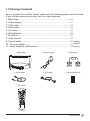
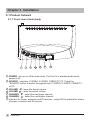
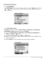
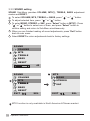
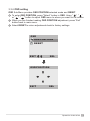
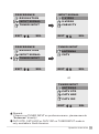
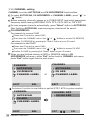
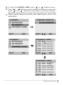
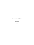
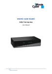
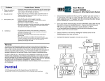
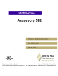
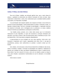
ProV
User Manual
Table of Contents
Chapter 1 Introduction
1.1 Important Notices............................................................................................... 2
1.2 Product Functions.............................................................................................. 2
1.3 Package Contents.............................................................................................. 3
Chapter 2 Installation
2.1 Product Outward................................................................................................ 4
2.1.1 Front view of main body................................................................................4
2.1.2 Rear view of main body................................................................................5
2.2 System Installation............................................................................................. 6
2.2.1 For analog TV and A/V devices connection............................................ 6
2.2.2 Connecting to the signal from other room................................................ 7
2.2.3 Long distance wiring connection................................................................ 8
Chapter 3 Operation Instruction
3.1 Initial Setting....................................................................................................... 9
3.2 IR Control............................................................................................................ 10
3.3 Advanced Setting............................................................................................... 11
3.3.1 MAIN MENU.................................................................................................. 11
3.3.2 PICTURE setting.......................................................................................... 11
3.3.3 SOUND setting............................................................................................. 12
3.3.4 OSD setting................................................................................................... 13
3.3.5 PREFERENCE setting................................................................................. 14
Including RESOLUTION, INPUT SIGNAL and TUNER INPUT selection
3.3.6 CHANNEL setting......................................................................................... 16
Chapter 4 Other Information
4.1 Troubleshooting.................................................................................................. 18
4.2 Specifications...................................................................................................... 19
Table of Contents
1
Chapter 1 Introduction
Thanks for your purchase of this product. With this product, you can use your
computer monitor to watch TV/CATV, VCR, LD, DVD or play video game. Without
turning on your computer, the system set up is very easy and there is no
additional requirement for hardware or software. You don't need to learn a
complicated set up procedure and you can enjoy your product with just plug and
play.
1.1 Important Notices
Please use the product under a normal environment
1. Try to avoid the following circumstances.
Heat or direct sunlight places
Location with huge magnetic field
Unstable or vibrational places
Exposure to rain or moisture places
2. For the unauthorized person, please don't serve this product : otherwise the
damage caused by unauthorized servicing is not covered by warranty.
3. Unplug this product from AC outlet and remove batteries from IR control, when
this product is left unused for a long time.
1.2 Product Functions
With the advanced video processing technology, the TV composite VIDEO, SVIDEO signal can be displayed on PC monitor.
Double scan conversion (15.75 KHz to 31.5 Khz).
View external video on any VGA monitor (CRT, LCD or Plasma).
With built-in audioloop, the audio signal coming from PC can pass through to
PC speakers at any circumstance (ProV power on or power off).
Full screen, true color display.
Support one of following TV systems : NTSC, PAL (B/G, D/K, I), PAL M/N or
Scan D/K TV system.
Built-in TV tuner for receiving terrestrial or cable TV.
Easy operation - With one button to switch signals coming from composite
VIDEO, S-VIDEO, CABLE/TV or PC.
Automatic channel scan to detect the program channels.
On screen display operation with IR remote controller.
MTS supported for NTSC system. (Available in North America & Taiwan market.)
2
Introduction
1.3 Package Contents
As you unpack the product, please make sure the following items were included.
If any of these items are missing, call your local agencies.
1. Main body .......................................................................................x1
2. Power supply ..................................................................................x1
3. VGA cable.......................................................................................x1
4. Audio cable .....................................................................................x1
5. A/V cable .........................................................................................x1
6. AAA batteries ..................................................................................x2
7. IR control.........................................................................................x1
8. User manual....................................................................................x1
9. Coaxial cable ..................................................................................x1 (option)
10. Two way splitter ............................................................................x1 (option)
11. Indoor amplifier (HDA-series)........................................................x1 (option)
1. Main body
4. Audio cable
2. Power supply
5. A/V cable
3. VGA cable
6. AAA batteries x2
7. IR control
Introduction
3
Chapter 2 Installation
2.1 Product Outward
2.1.1 Front view of main body
1
1
2
3
4
5
6
7
4
2
3
4
5
6
7
POWER : turn on or off the main body. The ProV is in standby mode when
power is off.
SOURCE : selection C-VIDEO, S-VIDEO, CABLE/TV, PC. Press the
"SOURCE" button to switch the signals from C-VIDEO, S-VIDEO, CABLE/TV
or PC.
VOLUME
: lower the sound volume.
VOLUME
: raise the sound volume.
CHANNEL
: select the next lower channel.
CHANNEL
: select the next higher channel.
Indicator for Power, autoscan and IR receiver : using LED to indicate the status
of power, autoscan and IR receiver.
Installation
2.1.2 Rear view of main body
9
8
7
6
5
2
4
1
3
1
RF IN
Please connect to antenna or cable TV signal.
2
PHONE OUT
Please connect the PHONE OUT to your speakers.
3
PHONE IN
Please connect the audio from sound card to PHONE IN. Thus, even if your
product is off, you should be able to hear the sound from speakers.
4
AUDIO (L & R) INPUT
Please connect the external AUDIO INPUT to box.
5
VIDEO INPUT
Please connect the external video from VCR, LD, V8 or video game to the
VIDEO INPUT of box.
6
S-VIDEO INPUT
If the external video is s-video, please connect to the S-VIDEO INPUT of box.
7
VGA INPUT
Please use the 15-pin VGA cable in the package contents. Connect one side to
the VGA output of your computer and the other side to VGA INPUT of product.
8
VGA OUTPUT
Please connect your monitor 15 pin connector to here.
9
DC IN
Please connect to your 12V power supply.
Installation
5
2.2 System Installation :
Please refer to the example closest to your configuration
2.2.1 For analog TV and A/V devices connection
Monitor
Speaker
Cable
VGA output
from PC
Antenna
Sound output
from PC
RCA A/V cable
DVD/VCR/LD/IRD
S-VIDEO cable
Camera
Video game
Adapter
Please turn off the power of all devices before connection.
Audio/video connection:
For audio connection, please use RCA audio(L+R) connector. For video connection, please
choose either RCA video connector or s-video connector.
Moreover, for connection to monitor alone please omit those connections associated with PC.
6
Installation
2.2.2 Connecting to the signal from other room :
When there is no signal available in your room, and must connecting to
signal from other room
Two way splitter
VCR / Cable box
TV
Cable or antenna
outlet
Monitor
Speaker
VGA output
from PC
Sound output
from PC
RCA A/V cable
Adapter
DVD/VCR/LD/ IRD
S-VIDEO cable
Camera
Video game
Please turn off the power of all devices before connection.
Audio/video connection:
For audio connection, please use RCA audio(L+R) connector. For video connection, please
choose either RCA video connector or s-video connector.
Moreover, for connection to monitor alone please omit those connections associated with PC.
Installation
7
2.2.3 Long distance wiring connection :
When there is no TV signal outlet available in your room and you must have a
long distance wiring to the signal from other room, it is strongly recommended
to install a low noise indoor amplifier (HDA-series), to compensate the signal
loss caused by splitter and long distance wiring. For more information about
drop amplifier, please contact your local dealer. Moreover, please omit the
splitter connection in following figure if there is no cable modem in your
application.
Cable or antenna
outlet
AC outlet
The best location of indoor
amplifier is near by the
television.
VCR / Cable box
HDA-series
Indoor amp.
12 ~16VDC
200mA
OUT+7dB
ZINWELL
INPUT
1GHz Drop Amplifier
5~40 54~1000MHz
HDA-R4-2
TAIWAN
OUT+7dB
TV
(PC in the room)
VGA output
from PC
Two way splitter
Cable modem
For other connections not seen in this figure, please refer to p6, p7.
8
Installation
Chapter 3 Operation Instruction
3.1 Initial Setting
When you finished the connections of product, because all the function settings
are in the IR control, please refer the following instructions of IR control and start
the system setting.
Steps:
1. Please install 2 AAA batteries into IR control.
2. Please refer to p6, 7, 8 for your configuration.
3. Turn on the power.
4. Press the "SOURCE" button to select signal source.
5. Press the "SCAN" button to scan and memorize program channels.
6. After the auto scan is finished, please press " "," " or channel number keys
to select the channel. (Autoscan function is available on partial NTSC & PAL
system market.)
Operation Instruction
9
3.2 IR Control
14 CH+ / CHSelect channels up or down
13 Exit
Exit the current menu
selection and return to
the parent menu. Press
this key repeatedly to
close all menus.
12 Select
Select the currently
highlighted menu item
11 XVGA/VGA
Select resolution of
1024x768, 800x600 and
640x480
10 TV/PC
Toggle between TV
mode and PC mode
9 0~9 Number Keys
Used to select cable TV
or Terrestrial program
8 SCAN
Scan program channels
automatically and save
scanned channel
10
Operation Instruction
1 POWER
Switch between power-on
and power-off
2 VOL+ / VOL Adjust the volume
3 Menu
Display the main menu
4 Mute
Turn the sound on/off
5
Adjust the selected item on
menu or adjust the volume
Press to select desired item
on the menu or select
channels up or down
6 Source
Select input sources of :
C-VIDEO, S-VIDEO,
CABLE/TV, PC
7 RECALL
Display the last selected
channel
3.3 Advanced Setting
3.3.1 MAIN MENU
The MAIN MENU shown below displays when you press "Menu" button. Press
" " or " " button to select one of them below and press "Select" button to
enter Sub-Menu.
MAIN MENU
PICTURE
SOUND
OSD
PREFERENCE
CHANNEL
EXIT
SEL
3.3.2 PICTURE setting
PICTURE Sub-Menu provides BRIGHTNESS, CONTRAST, SATURATION,
SHARPNESS, HUE adjustment modes and RESET.
1 To select BRIGHTNESS, CONTRAST, SATURATION, SHARPNESS or
HUE, press " " or " " button.
2 To adjust selected item, press "
" or " " button.
3 When you are finished making all picture adjustments, press "Exit" button
back to main menu.
4 Select RESET to return adjustments back to factory settings.
PICTURE
BRIGHTNESS
CONTRAST
SATURATION
SHARPNESS
HUE
100
Operation Instruction
11
3.3.3 SOUND setting
SOUND Sub-Menu provides VOLUME, MTS(*), TREBLE, BASS adjustment
modes and RESET.
1 To select VOLUME, MTS, TREBLE or BASS, press "
" or " " button.
2 To adjust selected item, press "
" or " " button.
3 To enter MONO, STEREO or SAP, press "Select" button in MTS(*). Press
" " or " " button to select one of them, and press "Select" button to
confirm setting and return to Sub-Menu simultaneously.
4 When you are finished making all sound adjustments, press "Exit" button
back to main menu.
5 Select RESET to return adjustments back to factory settings.
SOUND
VOLUME
MTS
TREBLE
BASS
RESET
40
SOUND
MTS
VOLUME
MTS
STEREO
TREBLE
SAP
MONO
BASS
RESET
EXIT
SEL
EXIT
SEL
MTS function is only available in North America & Taiwan market.
12
Operation Instruction
3.3.4 OSD setting
OSD Sub-Menu provides OSD POSITION selected mode and RESET.
1 To enter OSD POSITION, press "Select" button in OSD. Using "
", " "
or " ", "
" button to adjust OSD menu to where you want on the screen.
2 When you are finished making OSD POSITION adjustment, press "Exit"
button back to main menu.
3 Select RESET to return adjustments back to factory settings.
OSD
OSD POSITION
RESET
SEL
EXIT
OSD POSITION
EXIT
SEL
Operation Instruction
13
3.3.5 PREFERENCE setting
PREFERENCE Sub-Menu provides RESOLUTION, INPUT SIGNAL and
TUNER INPUT modes.
1
2
3
4
5
To select RESOLUTION , INPUT SIGNAL or TUNER INPUT, press " " or
" " button.
To enter "1024 x 768", "800 x 600" or "640 x 480", press "Select" button
in RESOLUTION. Press " " or " " button to select one of them, then
press "Select" button to confirm setting and return to Sub-Menu
simultaneously.
To enter C-VIDEO, S-VIDEO or CABLE/TV, press "Select" button in INPUT
SIGNAL, press " " or " " button to select one of them, and press
"Select" button to confirm setting and return to Sub-Menu simultaneously.
To enter ANTENNA or CATV, press "Select" button in TUNER INPUT, press
" " or " " button to select one of them,
and press "Select" button to confirm setting and return to Sub-Menu
simultaneously.
When you are finished making all selections, press "Exit" button back to
main menu.
PREFERENCE
RESOLUTION
RESOLUTION
1024x768
INPUT SIGNAL
800x600
TUNER INPUT
640x480
EXIT
SEL
EXIT
SEL
PAL system :
Have a good image quality, you can switch to 1024x768, 800x600.
The box with CATV STD, CATV HRC or CATV IRC on TUNER INPUT
mode is only available in North America.
14
Operation Instruction
PREFERENCE
RESOLUTION
INPUT SIGNAL
C-VIDEO
INPUT SIGNAL
S-VIDEO
TUNER INPUT
CABLE/TV
EXIT
SEL
PREFERENCE
RESOLUTION
INPUT SIGNAL
EXIT
SEL
TUNER INPUT
ANTENNA
CATV
TUNER INPUT
EXIT
SEL
EXIT
SEL
or
TUNER INPUT
ANTENNA
CATV STD
CATV HRC
CATV IRC
EXIT
SEL
Remark:
If there is no TUNER INPUT on preference menu, please execute
"Autoscan" directly!
CATV STD, CATV HRC or CATV IRC on TUNER INPUT mode is
only available in North America.
Operation Instruction
15
3.3.6 CHANNEL setting
CHANNEL provides AUTOSCAN and CH ADD/REMOVE functionalities.
1 To select AUTOSCAN, CH ADD/REMOV or CHANNEL LABEL, press "
" or
" " button.
2 Before scanning channels, please go to TUNER INPUT and select appropriate
frequency tables among ANTENNA, CATV STD, CATV HRC or CATV IRC.
3 To scan program channels automatically, press "Select" button in AUTOSCAN.
After finishing AUTOSCAN, scanned program channel will be saved.
4 CH ADD/REMOVE :
For example to remove CH60
Please use IR control to select CH60
Then enter the CHANNEL menu. Use " " or " " button to access CH REMOVE
Confirm CH REMOVE by pressing the "Select" button at your IR control.
For example to add CH60
Please use IR control to select CH60
Then enter the CHANNEL menu. Use " " or " " button to access CH ADD
Confirm CH ADD by pressing the "Select" button at your IR control
5
When you are finished making all ADD or REMOVE setting in CH
ADD/REMOVE sub-menu, press "Exit" button back to CHANNEL sub-menu,
press "Exit" button again back to main menu.
CHANNEL
CHANNEL
AUTOSCAN
AUTOSCAN
CH REMOVE
CH ADD
CHANNEL LABEL
EXIT
SEL
or
CHANNEL LABEL
EXIT
SEL
Autoscan function is available on partial NTSC & PAL system market.
CHANNEL
CHANNEL ADD
AUTOSCAN
CH 060 ADD
CH ADD
CHANNEL LABEL
EXIT
16
Operation Instruction
SEL
EXIT
SEL
5
6
7
To select the CHANNEL LABEL, press " " or " " up/down arrows.
Press " ", " " left/right arrows to highlight the selected column, then
press " " and " " up/down arrows to pick a numeral or character.
Repeat the same procedure to input channel number and channel label.
When all desired labels are finished, press "Exit" again to return to the
MAIN MENU.
CHANNEL
CHANNEL REMOVE
AUTOSCAN
CH 060 REMOVE
CH REMOVE
CHANNEL LABEL
EXIT
SEL
CHANNEL
EXIT
SEL
CHANNEL LABEL
------- ------- ----CH --- ----CH --- -----
AUTOSCAN
CH 060
CH REMOVE
CH
CH
CHANNEL LABEL
EXIT
SEL
EXIT
SEL
CHANNEL LABEL
-----CH --- ----CH --- ----CH --- ----CH --- ----CH 060 NHK
EXIT
SEL
Operation Instruction
17
Chapter 4 Other Information
4.1 Troubleshooting
Symptom
No picture on monitor
Solution
Make sure the power cord is connected to AC
outlet, DC plug is connected to DC IN port and
the power is on.
Check the connection of your source signal.
The IR control can't control
product
Make sure if batteries installed are not weak
batteries
If you still have difficulties that you can't resolve using the tips described above,
please unplug and plug in the AC cord to reset your product. Otherwise, please
18
Other Information
4.2 Specifications
POWER
12VDC 1.2A OUTPUT
VIDEO INPUT
Composite video RCA connector
S-VIDEO INPUT
S-Video 4-pin mini DIN
AUDIO INPUT
Stereo L+R RCA connectors
PHONE IN
Phone Jack 3.5
PHONE OUT
Phone Jack 3.5
RF IN
F-Female connector for NTSC system
IEC-Female connector for PAL D/K System
VGA INPUT
D-Sub 15 pin Male connector
VGA OUTPUT
D-Sub 15 pin Female connector
Power Consumption
15W nominal
Operating Temperature
5
Operating Humidity
5% ~ 80%
Dimensions
231.50 x 156.65 x 36.80 mm
Weight
Around 490g
IR Control
28 Buttons (AAA batteries x2)
~ 45
Other Information
19
Safety :
Tested To Comply
With FCC Standards
R
FOR HOME OR OFFICE USE
20
Other Information
IB02060799 Rev:C