1
^1 USER MANUAL ^2 Accessory 59E ^3 8-Channel 12-Bit ADC/DAC Board ^4 3Ax-603494-xUxx ^5 May 26, 2011 Single Source Machine Control Power // Flexibility // Ease of Use 21314 Lassen Street Chatsworth, CA 91311 // Tel. (818) 998-2095 Fax. (818) 998-7807 // www.deltatau.com Copyright Information © 2010 Delta Tau Data Systems, Inc. All rights reserved. This document is furnished for the customers of Delta Tau Data Systems, Inc. Other uses are unauthorized without written permission of Delta Tau Data Systems, Inc. Information contained in this manual may be updated from time-to-time due to product improvements, etc., and may not conform in every respect to former issues. To report errors or inconsistencies, call or email: Delta Tau Data Systems, Inc. Technical Support Phone: (818) 717-5656 Fax: (818) 998-7807 Email: [email protected] Website: http://www.deltatau.com Operating Conditions All Delta Tau Data Systems, Inc. motion controller products, accessories, and amplifiers contain static sensitive components that can be damaged by incorrect handling. When installing or handling Delta Tau Data Systems, Inc. products, avoid contact with highly insulated materials. Only qualified personnel should be allowed to handle this equipment. In the case of industrial applications, we expect our products to be protected from hazardous or conductive materials and/or environments that could cause harm to the controller by damaging components or causing electrical shorts. When our products are used in an industrial environment, install them into an industrial electrical cabinet or industrial PC to protect them from excessive or corrosive moisture, abnormal ambient temperatures, and conductive materials. If Delta Tau Data Systems, Inc. products are directly exposed to hazardous or conductive materials and/or environments, we cannot guarantee their operation. A Warning identifies hazards that could result in personal injury or death. It precedes the discussion of interest. WARNING A Caution identifies hazards that could result in equipment damage. It precedes the discussion of interest. Caution A Note identifies information critical to the user’s understanding or use of the equipment. It follows the discussion of interest. Note REVISION HISTORY REV. DESCRIPTION 1 2 3 4 5 6 CORR. TB3 HEADER P. 30, NEW SCHEMATIC UPDATED J3 JUMPER DESCRIPTION ADDED UL SEAL TO MANUAL COVER CORRECTED VOLTAGE RANGES (P. 5, 10-11); CORRECTED M-VARIABLE NAMES (P. 11-12) MANUAL REFORMATTING; ADDED POWER PMAC REFURBISHED UMAC MACRO SECTION DATE CHG APPVD 01/11/08 07/22/09 10/01/09 CP CP CP S.MILICI S.SATTARI S.FIERRO 8/11/10 DCDP R.N 10/15/10 DCDP 4/27/11 DCDP R.N R.N ACC-59E User Manual Table of Contents INTRODUCTION ................................................................................................................................................ 1 SPECIFICATIONS .............................................................................................................................................. 2 Environmental Specifications ............................................................................................................................. 2 Electrical Specifications ..................................................................................................................................... 2 Physical Specifications ....................................................................................................................................... 3 ADDRESSING ACC-59E..................................................................................................................................... 4 Turbo/Power UMAC, Macro Station Dip Switch Settings ................................................................................... 4 Legacy Macro Dip Switch Settings ..................................................................................................................... 4 Hardware Address Limitations ........................................................................................................................... 5 USING ACC-59E WITH TURBO UMAC........................................................................................................... 6 Setting Up the Analog Inputs (ADCs) ................................................................................................................. 6 Automatic ADC Read ..................................................................................................................................... 7 Manual ADC Read ....................................................................................................................................... 10 Testing the Analog Inputs ............................................................................................................................. 14 Using an Analog Input for Servo Feedback................................................................................................... 15 Analog Input Power-On Position.................................................................................................................. 16 Setting Up the Analog Outputs (DACs) ............................................................................................................ 17 Testing the Analog Outputs .......................................................................................................................... 17 USING ACC-59E WITH POWER UMAC ........................................................................................................ 18 Setting Up the Analog Inputs (ADCs) ............................................................................................................... 18 Automatic ADC Read ................................................................................................................................... 19 Using an Analog Input for Servo Feedback................................................................................................... 24 Analog Input Power-On Position.................................................................................................................. 25 Manual ADC Read Using ACC-59E Structures............................................................................................. 26 Testing the Analog Inputs ............................................................................................................................. 32 Setting Up the Analog Outputs (DACs) ............................................................................................................ 33 Testing the Analog Outputs .......................................................................................................................... 33 Using the Analog Outputs with ACC-59E Power PMAC Structures............................................................... 33 USING ACC-59E WITH TURBO UMAC MACRO ......................................................................................... 36 Quick Review: Nodes and Addressing .............................................................................................................. 37 Enabling MACRO Station ADC Processing...................................................................................................... 39 Transferring Data over I/O Nodes ..................................................................................................................... 42 Automatic I/O Node Data Transfer: MI173, MI174, MI175........................................................................... 43 Manual I/O Node Data Transfer: MI19…MI68............................................................................................. 48 Using an Analog Input for Servo Feedback over MACRO ............................................................................. 54 Analog Input Power-On Position over MACRO ............................................................................................ 55 Setting Up the Analog Outputs (DACs) over MACRO ...................................................................................... 56 Testing the Analog Outputs .......................................................................................................................... 56 Analog Output (DAC) MACRO I/O Transfer ................................................................................................ 57 ACC-59E LAYOUT & PINOUTS ..................................................................................................................... 60 Sample Wiring Diagram ................................................................................................................................... 62 P1: Backplane Bus ........................................................................................................................................... 63 TB1: External Power Supply ............................................................................................................................ 63 DB15 Breakout Option ..................................................................................................................................... 64 J1 Top: ADC1 through ADC4 ...................................................................................................................... 64 J1 Top: ADC5 through ADC8 ...................................................................................................................... 64 J1 Bottom: DAC1 through DAC4 ................................................................................................................. 65 J2 Bottom: DAC5 through DAC8 ................................................................................................................. 65 Terminal Block Option ..................................................................................................................................... 66 TB1 Top: ADC1 through ADC4.................................................................................................................... 66 Table of Contents i Accessory 59E TB2 Top: ADC5 through ADC8.................................................................................................................... 66 TB3 Top: Power Supply Outputs .................................................................................................................. 67 TB1 Bottom – DAC1 through DAC4 ............................................................................................................. 68 TB2 Bottom – DAC5 through DAC8 ............................................................................................................. 68 TB3 Bottom – Power Supply Outputs............................................................................................................ 69 APPENDIX A: JUMPER SETTINGS ............................................................................................................... 70 APPENDIX B: SCHEMATICS.......................................................................................................................... 71 APPENDIX C: USING POINTERS................................................................................................................... 72 Table of Contents ii ACC-59E User Manual INTRODUCTION The Accessory 59E (ACC-59E) is a 3U Euro bus compatible card for the UMAC rack family (Turbo, Power, and Macro). It has eight 12-bit Analog Inputs and eight 12-bit Analog Outputs. ACC-59E: D-Sub Option Addressing ACC-59E ACC-59E: Terminal Block Option 1 Accessory 59E SPECIFICATIONS Environmental Specifications Description Operating Temperature Storage Temperature Humidity Specification Notes 0 °C to 45 °C -25 °C to 70 °C 10% to 95% Non-Condensing Electrical Specifications Power Requirements Whether providing the ACC-59E with power from the 3U backplane bus through P1 or externally (standalone mode) through TB1, the power requirements (± 10%) are: +5 V @ 110 mA +15 V @ 75 mA -15 V @ 95 mA The DAC outputs are optically isolated and should not be sharing the same ±15 V power supply with the non-optically isolated ADCs. Note ACC-59E Fuse Manufacturer Specification Delta Tau Part Number Little Fuse 125 V @ 2.0 A 273.500 ADC Bandwidth The ADC input cutoff frequency is around 300 Hz. DAC Bandwidth The DAC output cutoff frequency is around 1.5 kHz. Adjustment Potentiometers (Pots) Channel 1 2 3 4 5 6 7 8 ADC Pots R8 R16 R24 R32 R7 R15 R23 R31 DAC Pots R36 R37 R50 R51 R64 R65 R78 R79 Pots R34 and R35 (for Delta Tau’s internal use) are used to adjust the ADCs’ voltage references. Note Specifications 2 ACC-59E User Manual ADC and DAC Chips The Analog-to-Digital Converter (ADC) chip used in ACC-59E is the MAX180 monolithic device manufactured by Maxim Integrated Products. These devices have a 12-bit resolution with 1 LSB linearity specification. For more details on the ADC chips, please refer to the data sheet published by the manufacturer: Document 19-3950; Rev 0, 6/91 Complete, 8-Channel, 12-Bit Data Acquisition Systems Maxim Integrated Products The Digital-to-Analog Converter (DAC) chip used in ACC-59E is the DAC7625 manufactured by BurrBrown Corporation. This device is a 12-bit quad voltage output digital-to-analog converter with guaranteed 12-bit monotonic performance from –40 C to +85 C. For more details about the DAC chips, please refer to the data sheet published by the manufacturer: DAC7624 and DAC7625 12-Bit Quad Voltage Output Digital-To-Analog Converter Burr-Brown Corporation Physical Specifications Description Specification Notes FRONT-MC1,5/12-ST3,81 Terminal Block Connectors FRONT-MC1,5/5-ST3,81 Terminal Blocks from Phoenix Contact (UL-94V0) FRONT-MC1,5/3-ST3,81 DB Option Connectors DB15 Female UL-94V0 Addressing ACC-59E 3 Accessory 59E ADDRESSING ACC-59E Dip switch SW1 specifies the base address of the ACC-59E in a 3U TURBO / POWER UMAC, or MACRO Station rack. Turbo/Power UMAC, Macro Station Dip Switch Settings Chip Select Base Address (TURBO/MACRO) and Base Offset (POWER) SW1 Positions 6 2 1 ON ON ON ON ON OFF ON OFF ON ON OFF OFF ON ON ON ON ON ON ON ON ON ON ON ON ON ON ON ON ON OFF ON OFF ON ON OFF OFF ON ON ON ON OFF OFF OFF OFF ON ON ON ON ON ON ON ON ON OFF ON OFF ON ON OFF OFF OFF OFF OFF OFF ON ON ON ON POWER Offset Index (n) TURBO MACRO CS10 Y:$78C00 Y:$79C00 Y:$7AC00 Y:$7BC00 Y:$8800 Y:$9800 Y:$A800 Y:$B800 $A00000 $A08000 $A10000 $A18000 0 4 8 12 ON ON ON ON CS12 Y:$78D00 Y:$79D00 Y:$7AD00 Y:$7BD00 Y:$8840 Y:$9840 Y:$A840 Y:$B840 $B00000 $B08000 $B10000 $B18000 1 5 9 13 CS14 Y:$78E00 Y:$79E00 Y:$7AE00 Y:$7BE00 Y:$8880 Y:$9880 Y:$A880 Y:$B880 $C00000 $C08000 $C10000 $C18000 2 6 10 14 CS16 Y:$78F00 Y:$79F00 Y:$7AF00 Y:$7BF00 Y:$88C0 Y:$98C0 Y:$A8C0 Y:$B8C0 $D00000 $D08000 $D10000 $D18000 3 7 11 15 Note 5 4 3 NA NA NA NA The ACC-59E can only be assigned to Chip Select 10, 12, or 14. ON designates Closed. OFF designates Open. Factory default is all ON. The maximum addressable number of ACC-59Es (or similar type accessories) in a single rack is 12. Legacy Macro Dip Switch Settings Chip Select 10 12 14 16 Base Address (Alternate) 6 SW1 Positions 5 4 3 Y:$B800 (Y:$FFE0) ON (OFF) ON (OFF) Y:$B840 (Y:$FFE8) ON (OFF) ON (OFF) Y:$B880 (Y:$FFF0) ON (OFF) ON (OFF) Y:$B8C0 (Y:$FFF8) 2 1 ON OFF OFF ON OFF OFF ON OFF OFF OFF OFF ON NA The Legacy Macro base addresses are double mapped. Set SW1 positions 5 & 6 to OFF if the alternate addressing is desired. Note Addressing ACC-59E 4 ACC-59E User Manual Hardware Address Limitations Historically, two types of accessory cards have been designed for the UMAC 3U bus type rack; type A and type B cards. They can be sorted out as follows: Possible Number Maximum Number of Addresses of cards in 1 rack Name Type Category ACC-9E ACC-10E ACC-11E ACC-12E A A A A General I/O General I/O General I/O General I/O 4 4 4 4 12 ACC-14E ACC-28E ACC-36E ACC-53E ACC-57E ACC-58E B B B B B B General I/O Analog I/O Analog I/O Feedback Feedback Feedback 16 16 16 16 16 16 16 ACC-59E B Analog I/O 12 12 ACC-65E ACC-66E ACC-67E ACC-68E B B B B General I/O General I/O General I/O General I/O 16 16 16 16 16 ACC-84E B Feedback 12 12 Addressing Type A and Type B accessory cards in a UMAC or MACRO station rack requires paying attention to the following set of rules: Populating Rack with Type A Cards Only (No Conflicts) In this mode, the card(s) can potentially use any available Address/Chip Select. Note Type A cards can have up to 4 different base addresses. Knowing that each card can be configured (jumper settings) to use the lower, middle or higher byte of a specific base address, it is possible to populate a single rack with a maximum of 12 Type A accessory cards. Populating Rack with Type B Cards Only (No Conflicts) In this mode, the card(s) can potentially use any available Address/Chip Select. Populating Rack with Type A & Type B Cards (Possible Conflicts) Typically, Type A and Type B cards should not share the same Chip Select. If this configuration is possible, then the next couple of rules does not apply, and can be disregarded. Type A cards cannot share the same Chip Select as Type B cards. Type A cards can share the same Chip Select as Type B general I/O cards. However, in this mode, Type B cards naturally use the lower byte (default), and Type A cards must be set up (jumper settings) to the middle/high byte of the selected base address. Addressing ACC-59E 5 Accessory 59E USING ACC-59E WITH TURBO UMAC Setting Up the Analog Inputs (ADCs) The A/D converter chips used on the ACC-59E multiplex the resulting data, and therefore it is mandatory to read each input one at a time. With Turbo UMAC, this can be done in two ways: Automatic Read Manual (semi-automatic) Read The automatic read feature is available with Turbo firmware version 1.936 and newer. It supports up to two ACC-59E cards in one rack. Note One should use the automatic read method when one wants to use the ADCs for servo feedback. One should use the manual read method when one needs to read ADCs from more than two ACC-36E or ACC-59E cards or when one wants the timing of the ADC conversion to occur exactly when specified, rather than at an automatic time that the user does not control. Using ACC-59E with Turbo UMAC 6 ACC-59E User Manual Automatic ADC Read The automatic read function demultiplexes the data into individual registers and stores them once every I5060 phase cycles in accessible memory locations. It can handle up to a total of 32 ADC channels (16 pairs). There are 16 ADCs (8 pairs) per base address (or ACC-59E card) for a maximum of 2 base addresses (or two ACC-59E cards) as shown below: Pair # 1 2 3 4 5 6 7 8 1st ACC-59E ADC#1 & ADC#9 ADC#2 & ADC#10 ADC#3 & ADC#11 ADC#4 & ADC#12 ADC#5 & ADC#13 ADC#6 & ADC#14 ADC#7 & ADC#15 ADC#8 & ADC#16 Pair # 9 10 11 12 13 14 15 16 2nd ACC-59E ADC#1 & ADC#9 ADC#2 & ADC#10 ADC#3 & ADC#11 ADC#4 & ADC#12 ADC#5 & ADC#13 ADC#6 & ADC#14 ADC#7 & ADC#15 ADC#8 & ADC#16 The ACC-59E has only 8 ADC channels, which is less than what the automatic read function can handle. Thus, one configures the software to explicitly sample actually 16 ADCs (8 pairs) per card. However, in reality, the upper 8 ADCs (4 pairs) are ignored (i.e., ADC#9 thru ADC#16), and only the lower 8 are used. These are the necessary steps for setting up the automatic read function: 1. Configure A/D Processing Ring Size: I5060. This is the number of ADC pairs to be demuxed. I5060 = (Number of ADC Pairs to Sample) Note Saving I5060 to a value greater than zero, the A/D Convert Enable I5080 is automatically set to 1 on power-up or reset. Subsequently setting I5080 to 0, the user can suspend the de-multiplexing, to be resumed by setting I5080=1. Each ADC is automatically updated every I5060 phase cycles. 2. Configure A/D Ring Pointers: I5061 thru I5076. I5061 through I5068 specify the offset widths (hex) of the first 8 pairs (1st ACC-59E). I5069 through I5076 specify the offset widths (hex) of the second 8 pairs (2nd ACC-59E). $(Offset Width) = $(Card Base Address) – $078800 3. Configure A/D Ring Convert Codes: I5081 thru I5096. I5081 through I5088 define the voltage modes for each of the first 8 pairs (1st ACC-59E). I5089 through I5096 define the voltage modes for each of the second 8 pairs (2nd ACC-59E). Setup I-Variable Definition of n Mode Voltages n = ADC# - 1 Unipolar Only positive I5081 through I5096 = n n = ADC# + 7 Bipolar Positive/Negative 4. Assign M-Variables to demuxed data registers, then Save and reset ($$$). Using ACC-59E with Turbo UMAC 7 Accessory 59E Automatic ADC Read Example 1 Setting up Turbo UMAC with an ACC-59E at base address $078C00 to automatically read all 8 ADCs, allowing the user to choose unipolar or bipolar mode: 1. A/D Processing Ring Size I5060=8 2. ; Demux 8 ADC pairs A/D Ring Pointers I5061,8=$400 ; ADC pairs 1 through 8 offset width: $400 = $078C00-$78800 3. A/D Convert Codes Pair # 1 2 3 4 5 6 7 8 Note Unipolar I5081=0 I5082=1 I5083=2 I5084=3 I5085=4 I5086=5 I5087=6 I5088=7 ; ; ; ; ; ; ; ; ADC#1 ADC#2 ADC#3 ADC#4 ADC#5 ADC#6 ADC#7 ADC#8 Bipolar Unipolar Unipolar Unipolar Unipolar Unipolar Unipolar Unipolar Unipolar I5081=8 I5082=9 I5083=10 I5084=11 I5085=12 I5086=13 I5087=14 I5088=15 ; ; ; ; ; ; ; ; ADC#1 ADC#2 ADC#3 ADC#4 ADC#5 ADC#6 ADC#7 ADC#8 Bipolar Bipolar Bipolar Bipolar Bipolar Bipolar Bipolar Bipolar These convert codes are applicable to ADCs #9 thru #16 as well by definition, but knowing that the ACC-59E carries only 8 channels, they can be ignored. 4. Assigning M-Variables to Demuxed Data Registers Unipolar M5061->Y:$003400,12,12,U M5062->Y:$003402,12,12,U M5063->Y:$003404,12,12,U M5064->Y:$003406,12,12,U M5065->Y:$003408,12,12,U M5066->Y:$00340A,12,12,U M5067->Y:$00340C,12,12,U M5068->Y:$00340E,12,12,U Note Bipolar ; ; ; ; ; ; ; ; ADC#1 ADC#2 ADC#3 ADC#4 ADC#5 ADC#6 ADC#7 ADC#8 Unipolar Unipolar Unipolar Unipolar Unipolar Unipolar Unipolar Unipolar M5061->Y:$003400,12,12,S M5062->Y:$003402,12,12,S M5063->Y:$003404,12,12,S M5064->Y:$003406,12,12,S M5065->Y:$003408,12,12,S M5066->Y:$00340A,12,12,S M5067->Y:$00340C,12,12,S M5068->Y:$00340E,12,12,S ; ; ; ; ; ; ; ; ADC#1 ADC#2 ADC#3 ADC#4 ADC#5 ADC#6 ADC#7 ADC#8 Bipolar Bipolar Bipolar Bipolar Bipolar Bipolar Bipolar Bipolar Issue a Save and reset ($$$) after download to enable the A/D ring processing If the convert code is unipolar, the M-Variable assigned to read the ADC result must also be unipolar Using ACC-59E with Turbo UMAC 8 ACC-59E User Manual Automatic ADC Read Example 2 Another ACC-59E has been added to produce a total of two cards at $078C00 and $079C00, respectively. 1. A/D Processing Ring Size I5060=16 ; Demux 16 ADC pairs 2. A/D Ring Pointers I5061,8=$400 I5069,8=$1400 ; ADC pairs 1 thru 8 offset width $400 = $078C00 - $78800 ; ADC pairs 9 thru 16 offset width $1400 = $079C00 - $078800 3. A/D Convert Codes 2nd ACC-59E 1st ACC-59E Pair# 1 2 3 4 5 6 7 8 9 10 11 12 13 14 15 16 Unipolar I5081=0 I5082=1 I5083=2 I5084=3 I5085=4 I5086=5 I5087=6 I5088=7 I5089=0 I5090=1 I5091=2 I5092=3 I5093=4 I5094=5 I5095=6 I5096=7 ; ; ; ; ; ; ; ; ; ; ; ; ; ; ; ; ADC#1 ADC#2 ADC#3 ADC#4 ADC#5 ADC#6 ADC#7 ADC#8 ADC#1 ADC#2 ADC#3 ADC#4 ADC#5 ADC#6 ADC#7 ADC#8 1st 1st 1st 1st 1st 1st 1st 1st 2nd 2nd 2nd 2nd 2nd 2nd 2nd 2nd Bipolar ACC-59E ACC-59E ACC-59E ACC-59E ACC-59E ACC-59E ACC-59E ACC-59E ACC-59E ACC-59E ACC-59E ACC-59E ACC-59E ACC-59E ACC-59E ACC-59E Unipolar Unipolar Unipolar Unipolar Unipolar Unipolar Unipolar Unipolar Unipolar Unipolar Unipolar Unipolar Unipolar Unipolar Unipolar Unipolar I5081=8 I5082=9 I5083=10 I5084=11 I5085=12 I5086=13 I5087=14 I5088=15 I5089=8 I5090=9 I5091=10 I5092=11 I5093=12 I5094=13 I5095=14 I5096=15 ; ; ; ; ; ; ; ; ; ; ; ; ; ; ; ; ADC#1 ADC#2 ADC#3 ADC#4 ADC#5 ADC#6 ADC#7 ADC#8 ADC#1 ADC#2 ADC#3 ADC#4 ADC#5 ADC#6 ADC#7 ADC#8 1st 1st 1st 1st 1st 1st 1st 1st 2nd 2nd 2nd 2nd 2nd 2nd 2nd 2nd ACC-59E ACC-59E ACC-59E ACC-59E ACC-59E ACC-59E ACC-59E ACC-59E ACC-59E ACC-59E ACC-59E ACC-59E ACC-59E ACC-59E ACC-59E ACC-59E Bipolar Bipolar Bipolar Bipolar Bipolar Bipolar Bipolar Bipolar Bipolar Bipolar Bipolar Bipolar Bipolar Bipolar Bipolar Bipolar 4. Assigning M-Variables to Demuxed Data Registers 1st ACC-59E Bipolar ; ; ; ; ; ; ; ; ADC#1 ADC#2 ADC#3 ADC#4 ADC#5 ADC#6 ADC#7 ADC#8 1st 1st 1st 1st 1st 1st 1st 1st ACC-59E ACC-59E ACC-59E ACC-59E ACC-59E ACC-59E ACC-59E ACC-59E M5061->Y:$003400,12,12,S M5062->Y:$003402,12,12,S M5063->Y:$003404,12,12,S M5064->Y:$003406,12,12,S M5065->Y:$003408,12,12,S M5066->Y:$00340A,12,12,S M5067->Y:$00340C,12,12,S M5068->Y:$00340E,12,12,S ; ; ; ; ; ; ; ; ADC#1 ADC#2 ADC#3 ADC#4 ADC#5 ADC#6 ADC#7 ADC#8 1st 1st 1st 1st 1st 1st 1st 1st ACC-59E ACC-59E ACC-59E ACC-59E ACC-59E ACC-59E ACC-59E ACC-59E 2nd ACC-59E Unipolar M5061->Y:$003400,12,12,U M5062->Y:$003402,12,12,U M5063->Y:$003404,12,12,U M5064->Y:$003406,12,12,U M5065->Y:$003408,12,12,U M5066->Y:$00340A,12,12,U M5067->Y:$00340C,12,12,U M5068->Y:$00340E,12,12,U M5069->Y:$003410,12,12,U M5070->Y:$003412,12,12,U M5071->Y:$003414,12,12,U M5072->Y:$003416,12,12,U M5073->Y:$003418,12,12,U M5074->Y:$00341A,12,12,U M5075->Y:$00341C,12,12,U M5076->Y:$00341E,12,12,U ; ; ; ; ; ; ; ; ADC#1 ADC#2 ADC#3 ADC#4 ADC#5 ADC#6 ADC#7 ADC#8 2nd 2nd 2nd 2nd 2nd 2nd 2nd 2nd ACC-59E ACC-59E ACC-59E ACC-59E ACC-59E ACC-59E ACC-59E ACC-59E M5069->Y:$003410,12,12,S M5070->Y:$003412,12,12,S M5071->Y:$003414,12,12,S M5072->Y:$003416,12,12,S M5073->Y:$003418,12,12,S M5074->Y:$00341A,12,12,S M5075->Y:$00341C,12,12,S M5076->Y:$00341E,12,12,S ; ; ; ; ; ; ; ; ADC#1 ADC#2 ADC#3 ADC#4 ADC#5 ADC#6 ADC#7 ADC#8 2nd 2nd 2nd 2nd 2nd 2nd 2nd 2nd ACC-59E ACC-59E ACC-59E ACC-59E ACC-59E ACC-59E ACC-59E ACC-59E Issue a Save and reset ($$$) after downloading to enable the A/D ring processing. Note Using ACC-59E with Turbo UMAC 9 Accessory 59E Manual ADC Read The manual read method consists of selecting the desired channel with an M-Variable, reading it with another M-Variable, and then storing it into local memory. Following are the necessary steps for implementing the manual ADC read method. The following example parameters are for an ACC-59E at base address $078C00, allowing the user to choose to read unipolar or bipolar input modes: 1. Point an available M-Variable (12-bit wide) to the lower 12 bits of the ACC-59E base address. This is the “Data Read” register of the selected channel. It can be defined as follows: Unsigned (positive input voltage only) Data Read pointer for Unipolar Mode: M5000->Y:$078C00,0,12,U Signed (negative/positive input voltage) Data Read pointer for Bipolar Mode: M5001->Y:$078C00,0,12,S 2. Point an available M-Variable (24-bit wide unsigned) to the base address of the ACC-59E. This is the “Channel Select” Pointer. M5004->Y:$078C00,0,24,U 3. Point an M-Variable to the bit that indicates when the ADC has finished its conversion. This is the ADC Ready bit. It becomes 1 when the ADC conversion has finished. M5005->Y:$078F30,5,1 // ADC Ready Bit (Channels 1-8) The address of this bit is based on the card base address as follows: Base Address Y:$78C00 Y:$79C00 Y:$7AC00 Y:$7BC00 Y:$78D00 Y:$79D00 Y:$7AD00 Y:$7BD00 Y:$78E00 Y:$79E00 Y:$7AE00 Y:$7BE00 Y:$78F00 Y:$79F00 Y:$7AF00 Y:$7BF00 ADC Ready Bit M5005->Y:$078F30,5,1 M5005->Y:$078F34,5,1 M5005->Y:$078F38,5,1 M5005->Y:$078F3C,5,1 M5005->Y:$079F30,5,1 M5005->Y:$079F34,5,1 M5005->Y:$079F38,5,1 M5005->Y:$079F3C,5,1 M5005->Y:$07AF30,5,1 M5005->Y:$07AF34,5,1 M5005->Y:$07AF38,5,1 M5005->Y:$07AF3C,5,1 M5005->Y:$07BF30,5,1 M5005->Y:$07BF34,5,1 M5005->Y:$07BF38,5,1 M5005->Y:$07BF3C,5,1 Because the ADCs are multiplexed, there is only one ADC Ready Bit, since only one ADC will be processed at a time. Note Using ACC-59E with Turbo UMAC 10 ACC-59E User Manual 4. Using the Channel Select Pointer, specify the channel # (ADC #) and voltage mode, as follows: M5000 = ADC# - 1 M5001 = ADC# + 7 for Unipolar for Bipolar ADC # 1 2 3 4 5 6 7 8 Channel Select Value Unipolar Bipolar 0 8 1 9 2 10 3 11 4 12 5 13 6 14 7 15 5. Wait for the ADC Ready bit to become 1, then read and/or copy data from the Data Read M-Variables. Note These are only suggested definitions for the Data Read and Channel Select pointers. The user can choose whichever M-Variable numbering he or she desires. Using ACC-59E with Turbo UMAC 11 Accessory 59E ADC Manual Read Example PLCs Ultimately, the above procedure can be implemented in a PLC script to read all channels consecutively and consistently, creating a “custom automatic” function. Setting up Turbo UMAC with an ACC-59E at base address $078C00: Unipolar PLC Example Reads all 8 ADC channels of the ACC-59E successively as unipolar and stores the results. End Gat Del Gat Close #define DataRead #define ChSelect #define ADCReady DataRead->Y:$078C00,0,12,U ChSelect->Y:$078C00,0,24,U ADCReady->Y:$078F30,5,1 M5000 M5004 M5005 ; ; ; ; ; ; Data Read register Channel Select Pointer ADC Ready Bit Unsigned for unipolar Channel Select ADC Ready Bit #define #define #define #define #define #define #define #define P2001 P2002 P2003 P2004 P2005 P2006 P2007 P2008 ; ; ; ; ; ; ; ; Channel Channel Channel Channel Channel Channel Channel Channel ADC1 ADC2 ADC3 ADC4 ADC5 ADC6 ADC7 ADC8 1 2 3 4 5 6 7 8 ADC ADC ADC ADC ADC ADC ADC ADC storage storage storage storage storage storage storage storage Open PLC 1 Clear ChSelect=0 While(ADCReady != 1) EndWhile ADC1=DataRead ; Select ADC Channel #1 (ChSelect = ADC#-1) ; Wait for ADC conversion to finish ; Copy result into storage ChSelect=1 While(ADCReady != 1) EndWhile ADC2=DataRead ; Select ADC Channel #2 (ChSelect = ADC#-1) ; Wait for ADC conversion to finish ; Copy result into storage ChSelect=2 While(ADCReady != 1) EndWhile ADC3=DataRead ; Select ADC Channel #3 (ChSelect = ADC#-1) ; Wait for ADC conversion to finish ; Copy result into storage ChSelect=3 While(ADCReady != 1) EndWhile ADC4=DataRead ; Select ADC Channel #4 (ChSelect = ADC#-1) ; Wait for ADC conversion to finish ; Copy result into storage ChSelect=4 While(ADCReady != 1) EndWhile ADC5=DataRead ; Select ADC Channel #5 (ChSelect = ADC#-1) ; Wait for ADC conversion to finish ; Copy result into storage ChSelect=5 While(ADCReady != 1) EndWhile ADC6=DataRead ; Select ADC Channel #6 (ChSelect = ADC#-1) ; Wait for ADC conversion to finish ; Copy result into storage ChSelect=6 While(ADCReady != 1) EndWhile ADC7=DataRead ; Select ADC Channel #7 (ChSelect = ADC#-1) ; Wait for ADC conversion to finish ; Copy result into storage ChSelect=7 While(ADCReady != 1) EndWhile ADC8=DataRead Close ; Select ADC Channel #8 (ChSelect = ADC#-1) ; Wait for ADC conversion to finish ; Copy result into storage Using ACC-59E with Turbo UMAC 12 ACC-59E User Manual Bipolar PLC Example Reads all 8 ADC channels of the ACC-59E successively as bipolar and stores the results. End Gat Del Gat Close #define DataRead #define ChSelect #define ADCReady DataRead->Y:$078C00,0,12,S ChSelect->Y:$078C00,0,24,U ADCReady->Y:$078F30,5,1 M5001 M5004 M5005 ; ; ; ; ; ; Data Read register Channel Select Pointer ADC Ready Bit Signed for bipolar Channel Select ADC Ready Bit #define #define #define #define #define #define #define #define P2001 P2002 P2003 P2004 P2005 P2006 P2007 P2008 ; ; ; ; ; ; ; ; Channel Channel Channel Channel Channel Channel Channel Channel ADC1 ADC2 ADC3 ADC4 ADC5 ADC6 ADC7 ADC8 1 2 3 4 5 6 7 8 ADC ADC ADC ADC ADC ADC ADC ADC storage storage storage storage storage storage storage storage Open PLC 1 Clear ChSelect=8 While(ADCReady != 1) EndWhile ADC1=DataRead ; Select ADC Channel #1 (ChSelect = ADC#+7) ; Wait for ADC conversion to finish ; Copy result into storage ChSelect=9 While(ADCReady != 1) EndWhile ADC2=DataRead ; Select ADC Channel #2 (ChSelect = ADC#+7) ; Wait for ADC conversion to finish ; Copy result into storage ChSelect=10 While(ADCReady != 1) EndWhile ADC3=DataRead ; Select ADC Channel #3 (ChSelect = ADC#+7) ; Wait for ADC conversion to finish ; Copy result into storage ChSelect=11 While(ADCReady != 1) EndWhile ADC4=DataRead ; Select ADC Channel #4 (ChSelect = ADC#+7) ; Wait for ADC conversion to finish ; Copy result into storage ChSelect=12 While(ADCReady != 1) EndWhile ADC5=DataRead ; Select ADC Channel #5 (ChSelect = ADC#+7) ; Wait for ADC conversion to finish ; Copy result into storage ChSelect=13 While(ADCReady != 1) EndWhile ADC6=DataRead ; Select ADC Channel #6 (ChSelect = ADC#+7) ; Wait for ADC conversion to finish ; Copy result into storage ChSelect=14 While(ADCReady != 1) EndWhile ADC7=DataRead ; Select ADC Channel #7 (ChSelect = ADC#+7) ; Wait for ADC conversion to finish ; Copy result into storage ChSelect=15 While(ADCReady != 1) EndWhile ADC8=DataRead Close ; Select ADC Channel #8 (ChSelect = ADC#+7) ; Wait for ADC conversion to finish ; Copy result into storage Using ACC-59E with Turbo UMAC 13 Accessory 59E Testing the Analog Inputs The Analog Inputs can be brought into the ACC-59E as single ended (ADC+ & Ground) or differential (ADC+ & ADC-) signals. In single-ended mode, ADC- should to be tied to analog ground for full resolution and proper operation. Note Reading the input signals in software counts using the predefined M-Variables should show the following: ADC Input Single-Ended [V] Unipolar Mode 0 10 20 0 10 20 0 2047 4095 Bipolar Mode -10 0 10 -10 0 10 -2047 0 2047 Using ACC-59E with Turbo UMAC ADC+ <=> AGND Differential [V] Software ADC+ <=> ADCCounts 14 ACC-59E User Manual Using an Analog Input for Servo Feedback The ACC-59E analog inputs can be used as a feedback device for a servo motor. Note Refer to Delta Tau’s released application notes or Turbo User Manual for details on implementing cascaded-loop control (i.e., force, height control around position loop). For simplicity, the automatic ADC read function is recommended for this application. Example: Setting up Motor #1 with position and velocity feedback from ADC channel 1. The analog input is brought into the Encoder Conversion Table as a parallel Y word with no filtering: The equivalent code in Turbo PMAC I8000 Encoder Conversion Table parameters: I8000=$203400 I8001=$00C00C ; Unfiltered parallel pos of location Y:$3400 ; Width and Offset. (Processed Data Location) The position and velocity pointers are then set to the processed data address (i.e. $3502) I103=$3502 I104=$3502 ; Motor #1 position loop feedback address ; Motor #1 velocity loop feedback address Using ACC-59E with Turbo UMAC 15 Accessory 59E Analog Input Power-On Position Some analog devices are absolute along the travel range of the motor (e.g., in hydraulic piston applications). Generally, it is desirable to obtain the motor position (input voltage) on power up or reset. This procedure can be done in a simple PLC on power-up by writing the processed A/D data into the motor actual position register (suggested M-Variable Mxx62). Note If the automatic ADC read method is being used, waiting a delay of about ½ second after the PMAC boots should be allowed for processing the data before copying it into the motor actual position register. If the manual ADC read method is being used, it is recommended to add this procedure at the end of the manual read PLC, or in a subsequent PLC with ½ sec delay to allow data processing. Example: Reading Motor #1 position on power-up or reset, assuming that the automatic read function is used, and that M5061 is predefined to access ADC channel 1. End Gat Del Gat Close #define Mtr1ActPos Mtr1ActPos->D:$8B #define Ch1ADC M162 ; Motor #1 Actual Position (suggested M-Variables units of 1/32*I108) M5061 ; Channel #1 ADC Open PLC 1 Clear I5111=500*8388608/I10 While(I5111>0) EndW Mtr1ActPos=Ch1ADC*32*I108 Disable PLC 1 Close Using ACC-59E with Turbo UMAC ; ½ sec delay ; Motor #1 Actual Position (scaled to motor counts) ; Scan once on power-up or reset 16 ACC-59E User Manual Setting Up the Analog Outputs (DACs) WARNING In bipolar mode, the DAC output is not at zero volts on power-up or reset. It is required to set the corresponding MVariable (register) to 2047 for zero voltage output on powerup or reset. The M-Variable pointers for the analog outputs (DACs) on the ACC-59E are mapped as follows: DAC # 1 2 3 4 Address Location 12-bit Location Base Address + $8 [11:0] Base Address + $9 [11:0] Base Address + $A [11:0] Base Address + $B [11:0] DAC # 5 6 7 8 Address Location 12-bit Location Base Address + $8 [23:12] Base Address + $9 [23:12] Base Address + $A [23:12] Base Address + $B [23:12] Example: Suggested User M-Variables for DAC Output on Two ACC-59Es: 1st ACC-59E (Base Address $78C00) 2nd ACC-59E (Base Address $79C00) M6001->Y:$78C08,0,12 ; DAC Channel #1 M6002->Y:$78C09,0,12 ; DAC Channel #2 M6003->Y:$78C0A,0,12 ; DAC Channel #3 M6004->Y:$78C0B,0,12 ; DAC Channel #4 M6005->Y:$78C08,12,12 ; DAC Channel #5 M6006->Y:$78C09,12,12 ; DAC Channel #6 M6007->Y:$78C0A,12,12 ; DAC Channel #7 M6008->Y:$78C0B,12,12 ; DAC Channel #8 M6009->Y:$79C08,0,12 ; DAC Channel #1 M6010->Y:$79C09,0,12 ; DAC Channel #2 M6011->Y:$79C0A,0,12 ; DAC Channel #3 M6012->Y:$79C0B,0,12 ; DAC Channel #4 M6013->Y:$79C08,12,12 ; DAC Channel #5 M6014->Y:$79C09,12,12 ; DAC Channel #6 M6015->Y:$79C0A,12,12 ; DAC Channel #7 M6016->Y:$79C0B,12,12 ; DAC Channel #8 Testing the Analog Outputs The Analog Outputs out of the ACC-59E can be wired as single ended (DAC+ & Ground) or differential (DAC+ & DAC-) signals. Writing the software counts shown below to the corresponding M-Variables should result in the following voltages: DAC Software Single-Ended [V] Differential [V] Output Counts (Write) DAC+ AGND DAC+ DACUnipolar Mode 0 2047 4095 0 5 10 0 10 20 Bipolar Mode 0 2047 4095 -10 0 10 -20 0 20 Using ACC-59E with Turbo UMAC 17 Accessory 59E USING ACC-59E WITH POWER UMAC Setting Up the Analog Inputs (ADCs) The A/D converter chips used on the ACC-59E multiplex the resulting data, and therefore it is mandatory to read each input one at a time. With Power UMAC, this can be done in two ways: Automatic Read Manual (semi-automatic) Read One should use the automatic read method when one wants to use the ADCs for servo feedback. One should use the manual read method when one needs to read ADCs from more than two ACC-36E or ACC-59E cards or when one wants the timing of the ADC conversion to occur exactly when specified, rather than at an automatic time that the user does not control. With each method, either the PMAC Script or the C programming language can be used. Using ACC-59E with Power UMAC 18 ACC-59E User Manual Automatic ADC Read The automatic read function demultiplexes the data into individual registers and stores them once every AdcDemux.Enable phase cycles in accessible memory locations. It can handle up to a total of 32 ADC channels (16 pairs). There are 16 ADCs (8 pairs) per base address (or ACC-59E card) for a maximum of 2 base addresses (or two ACC-59E cards) as follows: Pair # 1 2 3 4 5 6 7 8 1st ACC-59E ADC#1 & ADC#9 ADC#2 & ADC#10 ADC#3 & ADC#11 ADC#4 & ADC#12 ADC#5 & ADC#13 ADC#6 & ADC#14 ADC#7 & ADC#15 ADC#8 & ADC#16 Pair # 9 10 11 12 13 14 15 16 2nd ACC-59E ADC#1 & ADC#9 ADC#2 & ADC#10 ADC#3 & ADC#11 ADC#4 & ADC#12 ADC#5 & ADC#13 ADC#6 & ADC#14 ADC#7 & ADC#15 ADC#8 & ADC#16 The ACC-59E has only 8 ADC channels, which is less than what the automatic read function can handle. Thus, one configures the software to explicitly sample actually 16 ADCs (8 pairs) per card. However, in reality, the upper 8 ADCs are ignored (i.e., ADC#9 thru ADC#16), and only the lower 8 are used. Using ACC-59E with Power UMAC 19 Accessory 59E These are the necessary steps for setting up the automatic read function: 1. Configure A/D Ring Pointers: AdcDemux.Address[i] . For each pair of index i, AdcDemux.Address[i] must be set to the Power PMAC I/O base offset. Typically, pairs 1 – 8 are assigned to the first ACC-59E, pairs 9-16 are assigned to the second ACC-59E. Ring Pointers Pair # Ring Pointers Pair # AdcDemux.Address[8] 1 9 AdcDemux.Address[1] AdcDemux.Address[9] 2 10 AdcDemux.Address[2] AdcDemux.Address[10] 3 11 AdcDemux.Address[3] AdcDemux.Address[11] 4 12 AdcDemux.Address[4] AdcDemux.Address[12] 5 13 AdcDemux.Address[5] AdcDemux.Address[13] 6 14 AdcDemux.Address[6] AdcDemux.Address[14] 7 15 AdcDemux.Address[7] AdcDemux.Address[15] 8 16 2. Configure A/D Ring Convert Codes: AdcDemux.ConvertCode[i]. The convert code allows the user to select the input mode, whether unipolar or bipolar, as well as the ADC channel number (ADC#) to sample. AdcDemux.Address[0] Setup Structure AdcDemux.ConvertCode[i] =$k00 Definition of k k = ADC# - 1 k = ADC# + 7 Mode Unipolar Bipolar Voltages Only Positive Positive/Negative 3. Configure A/D Processing Ring Size: AdcDemux.Enable. AdcDemux.Enable = Number of ADC Pairs to Demux Setting AdcDemux.Enable to a value greater than zero activates the automatic ADC read ring. Note 4. Access the A/D Results: The results are stored in the AdcDemux.ResultLow[i] and AdcDemux.ResultHigh[i] structures: 1st ACC-59E i 0 1 2 3 4 5 6 7 2nd ACC-59E ResultLow[i] ResultHigh[i] ADC#1 Result ADC#2 Result ADC#3 Result ADC#4 Result ADC#5 Result ADC#6 Result ADC#7 Result ADC#8 Result ADC#9 Result ADC#10 Result ADC#11 Result ADC#12 Result ADC#13 Result ADC#14 Result ADC#15 Result ADC#16 Result Note i 8 9 10 11 12 13 14 15 ResultLow[i] ResultHigh[i] ADC#1 Result ADC#2 Result ADC#3 Result ADC#4 Result ADC#5 Result ADC#6 Result ADC#7 Result ADC#8 Result ADC#9 Result ADC#10 Result ADC#11 Result ADC#12 Result ADC#13 Result ADC#14 Result ADC#15 Result ADC#16 Result Since the ACC-59E carries only 8 channels per card, only AdcDemux.ResultLow[i] will contain meaningful information; AdcDemux.ResultHigh[i] can be ignored. Each ADC pair is automatically updated every AdcDemux.Enable phase cycles. Using ACC-59E with Power UMAC 20 ACC-59E User Manual ADC Automatic Read Example 1 Setting up Power UMAC with an ACC-59E at I/O base address offset $A00000 to automatically read all 8 ADCs, allowing the user to choose unipolar or bipolar mode: 1. A/D Ring Pointers AdcDemux.Address[0] AdcDemux.Address[1] AdcDemux.Address[2] AdcDemux.Address[3] AdcDemux.Address[4] AdcDemux.Address[5] AdcDemux.Address[6] AdcDemux.Address[7] = = = = = = = = $A00000; $A00000; $A00000; $A00000; $A00000; $A00000; $A00000; $A00000; 2. A/D Convert Codes Pair # 1 2 3 4 5 6 7 8 // // // // // // // // ADC ADC ADC ADC ADC ADC ADC ADC #1 #2 #3 #4 #5 #6 #7 #8 Unipolar AdcDemux.ConvertCode[0]=$000; AdcDemux.ConvertCode[1]=$100; AdcDemux.ConvertCode[2]=$200; AdcDemux.ConvertCode[3]=$300; AdcDemux.ConvertCode[4]=$400; AdcDemux.ConvertCode[5]=$500; AdcDemux.ConvertCode[6]=$600; AdcDemux.ConvertCode[7]=$700; Note Pair Pair Pair Pair Pair Pair Pair Pair Bipolar // // // // // // // // ADC#1 ADC#2 ADC#3 ADC#4 ADC#5 ADC#6 ADC#7 ADC#8 AdcDemux.ConvertCode[0]=$800; AdcDemux.ConvertCode[1]=$900; AdcDemux.ConvertCode[2]=$A00; AdcDemux.ConvertCode[3]=$B00; AdcDemux.ConvertCode[4]=$C00; AdcDemux.ConvertCode[5]=$D00; AdcDemux.ConvertCode[6]=$E00; AdcDemux.ConvertCode[7]=$F00; // // // // // // // // ADC#1 ADC#2 ADC#3 ADC#4 ADC#5 ADC#6 ADC#7 ADC#8 These convert codes are applicable to ADCs #9 through #16 as well by definition, but knowing that the ACC-59E carries only 8 channels, they can be ignored. 3. A/D Processing Ring Size AdcDemux.Enable = 8; // Demux 8 ADC pairs 4. The resulting data is found in AdcDemux.ResultLow[i] Using ACC-59E with Power UMAC 21 Accessory 59E ADC Automatic Read Example 2 Another ACC-59E has been added to produce a total of two cards set at base offsets $A00000 and $B00000, respectively. 1. A/D Processing Ring Size AdcDemux.Enable = 16; // Demux 16 ADC pairs 2. A/D Ring Pointers AdcDemux.Address[0] AdcDemux.Address[1] AdcDemux.Address[2] AdcDemux.Address[3] AdcDemux.Address[4] AdcDemux.Address[5] AdcDemux.Address[6] AdcDemux.Address[7] = = = = = = = = $A00000; $A00000; $A00000; $A00000; $A00000; $A00000; $A00000; $A00000; // // // // // // // // ADC ADC ADC ADC ADC ADC ADC ADC Pair Pair Pair Pair Pair Pair Pair Pair #1 #2 #3 #4 #5 #6 #7 #8 AdcDemux.Address[8] AdcDemux.Address[9] AdcDemux.Address[10] AdcDemux.Address[11] AdcDemux.Address[12] AdcDemux.Address[13] AdcDemux.Address[14] AdcDemux.Address[15] = = = = = = = = $B00000; $B00000; $B00000; $B00000; $B00000; $B00000; $B00000; $B00000; // // // // // // // // ADC ADC ADC ADC ADC ADC ADC ADC Pair Pair Pair Pair Pair Pair Pair Pair #9 #10 #11 #12 #13 #14 #15 #16 2nd ACC-59E 1st ACC-59E 3. A/D Convert Codes Pair# Unipolar 1 2 3 4 5 6 7 8 9 10 11 12 13 14 15 16 4. AdcDemux.ConvertCode[0] =$000; AdcDemux.ConvertCode[1] =$100; AdcDemux.ConvertCode[2] =$200; AdcDemux.ConvertCode[3] =$300; AdcDemux.ConvertCode[4] =$400; AdcDemux.ConvertCode[5] =$500; AdcDemux.ConvertCode[6] =$600; AdcDemux.ConvertCode[7] =$700; AdcDemux.ConvertCode[8] =$000; AdcDemux.ConvertCode[9] =$100; AdcDemux.ConvertCode[10]=$200; AdcDemux.ConvertCode[11]=$300; AdcDemux.ConvertCode[12]=$400; AdcDemux.ConvertCode[13]=$500; AdcDemux.ConvertCode[14]=$600; AdcDemux.ConvertCode[15]=$700; Bipolar // // // // // // // // // // // // // // // // ADC#1 ADC#2 ADC#3 ADC#4 ADC#5 ADC#6 ADC#7 ADC#8 ADC#9 ADC#10 ADC#11 ADC#12 ADC#13 ADC#14 ADC#15 ADC#16 AdcDemux.ConvertCode[0] =$800; AdcDemux.ConvertCode[1] =$900; AdcDemux.ConvertCode[2] =$A00; AdcDemux.ConvertCode[3] =$B00; AdcDemux.ConvertCode[4] =$C00; AdcDemux.ConvertCode[5] =$D00; AdcDemux.ConvertCode[6] =$E00; AdcDemux.ConvertCode[7] =$F00; AdcDemux.ConvertCode[8] =$800; AdcDemux.ConvertCode[9] =$900; AdcDemux.ConvertCode[10]=$A00; AdcDemux.ConvertCode[11]=$B00; AdcDemux.ConvertCode[12]=$C00; AdcDemux.ConvertCode[13]=$D00; AdcDemux.ConvertCode[14]=$E00; AdcDemux.ConvertCode[15]=$F00; // // // // // // // // // // // // // // // // The resulting data is found in AdcDemux.ResultLow[i] Using ACC-59E with Power UMAC 22 ADC#1 ADC#2 ADC#3 ADC#4 ADC#5 ADC#6 ADC#7 ADC#8 ADC#9 ADC#10 ADC#11 ADC#12 ADC#13 ADC#14 ADC#15 ADC#16 ACC-59E User Manual Accessing AdcDemux Structures in C Code (Optional; For C Programmers) In order to use AdcDemux structures in C code, use the pointer to shared-memory data structure (pshm). For example, to read AdcDemux.ResultLow[0] , make sure that #include <RtGpShm.h> is in the header, and then access AdcDemux.ResultLow[0] by using pshm->AdcDemux.ResultLow[0] as an expression. See the following example. Example: Using Automatic ADC Result Structures in a CPLC #include <RtGpShm.h> #include <stdio.h> #include <dlfcn.h> void user_plcc() { /*** ADC Result Array Format ***\ ADC_Result[0] stores ADC Channel 1 result ADC_Result[1] stores ADC Channel 2 result ADC_Result[2] stores ADC Channel 3 result ADC_Result[3] stores ADC Channel 4 result ADC_Result[4] stores ADC Channel 5 result ADC_Result[5] stores ADC Channel 6 result ADC_Result[6] stores ADC Channel 7 result ADC_Result[7] stores ADC Channel 8 result*/ unsigned int index; // ADC Result Storage Array int ADC_Result[8]; // Access ADC results one by one in a for loop for(index = 0; index < 8; index++) { // Store ADC Result in array element ADC_Result[index] = pshm->AdcDemux.ResultLow[index]; /******Insert user code here, where ADC_Result elements can be used for the user's calculations*************/ } return; } Using ACC-59E with Power UMAC 23 Accessory 59E Using an Analog Input for Servo Feedback The ACC-59E analog inputs can be used as a feedback device for a servo motor. For simplicity, the automatic ADC read function is recommended for this application. This example assumes that the automatic ADC read function has already been configured and activated. Example: Setting up Motor #1 with position and velocity feedback from ADC channel 1. The analog input is brought into the Encoder Conversion Table (ECT) as a single read of a 32-bit register (in the Power PMAC IDE Software: Delta Tau Configure Encoder Conversion Table): The equivalent code in Power PMAC Structures: EncTable[1].type = 1; // Set entry type to 32-bit word read EncTable[1].pEnc = AdcDemux.ResultLow[0].a; // Set encoder address to ADC channel 1 EncTable[1].pEnc1 = Sys.pushm; // Unused; set to Sys.pushm EncTable[1].index1 = 20; // Shift left 20 to put source MSB in bit 31 EncTable[1].index2 = 0; // Shift left 0 to put source LSB into bit 0 EncTable[1].index3 = 0; // No limit on first derivative EncTable[1].index4 = 0; // No limit on second derivative EncTable[1].ScaleFactor = 1/pow(2,EncTable[1].index1); // Scale factor (1/(2^20)) The position and velocity pointers are then set to the processed data address: Motor[1].pEnc = EncTable[1].a; Motor[1].pEnc2 = EncTable[1].a; // Outer (position) loop source address // Inner (velocity) loop source address One can then adjust Motor[1].PosSf and Motor[1].Pos2Sf, the position and velocity scale factors, respectively, if necessary. Using AdcDemux structures in the ECT requires firmware version 1.2.1.116 or newer. Note Using ACC-59E with Power UMAC 24 ACC-59E User Manual Analog Input Power-On Position Some analog devices are absolute along the travel range of the motor (e.g., in hydraulic piston applications). Generally, it is desirable to obtain the motor position (input voltage) on power up or reset. The following example code will configure Motor #1 to use ADC channel 1 for the power-on position read as an unsigned signal with a scale factor of 1: Motor[1].pAbsPos = AdcDemux.ResultLow[0].a; Motor[1].AbsPosFormat = $00000C00; Motor[1].AbsPosSF = 1; // // // // Set position register to ADC channel 1 Use 12 bits starting at bit 0, unsigned (for signed, change to $01000C00) Scale factor of 1 Please refer to the description of Motor[n].AbsPosFormat in the Power PMAC Saved Data Structure Elements manual for further details. Using ACC-59E with Power UMAC 25 Accessory 59E Manual ADC Read Using ACC-59E Structures The manual read method with ACC-59E structures consists of selecting the desired channel with the ACC59E[n].ConvertCode structure, reading it with the ACC59E[n].ADCu or ACC59E[n].ADCs structure, and then storing it into local memory, where n is the index specified by the DIP switch SW1 setting of the card. Refer to the Addressing ACC-59E section of this manual for a list of values that the index n assumes. Note This procedure can be implemented in a PLC script to read all channels consecutively and consistently, creating a “custom automatic” function. Following are the necessary steps for implementing the manual ADC read method with structures to allow the user to choose to read unipolar or bipolar input modes: 1. Using the ACC59E[n].ConvertCode structure, specify the voltage mode for each ADC# desired: Set ACC59E[n].ConvertCode = ADC# - 1 for Unipolar Inputs Set ACC59E[n].ConvertCode = ADC# + 7 for Bipolar Inputs ADC# 1 2 3 4 5 6 7 8 Channel Select Pointer Value Unipolar Inputs Bipolar Inputs 0 8 1 9 2 10 3 11 4 12 5 13 6 14 7 15 2. Poll the ADC ready bit, ACC59E[n].ADCRdy, in a while loop until it becomes 1, and then read and/or copy the resulting data using the following structures: ACC59E[n].ADCu for ACC59E[n].ADCs for unipolar signals bipolar signals Using ACC-59E with Power UMAC 26 ACC-59E User Manual ADC Manual Read Example Script PLCs To set up Power UMAC with an ACC-59E at I/O base address offset $A00000, see the following examples. Unipolar Script PLC Example This example selects and reads channels 1 through 8 successively as unipolar in a PLC and stores the results for channels 1 through 8 in global variables ADC1 through ADC8. global global global global global global global global ADC1; ADC2; ADC3; ADC4; ADC5; ADC6; ADC7; ADC8; // // // // // // // // Channel Channel Channel Channel Channel Channel Channel Channel 1 2 3 4 5 6 7 8 ADC ADC ADC ADC ADC ADC ADC ADC storage storage storage storage storage storage storage storage variable variable variable variable variable variable variable variable Open PLC 1 ACC59E[0].ConvertCode = 0; While(ACC59E[0].ADCRdy != 1){} ADC1 = ACC59E[0].ADCu; // Select Channel 1 // Wait for ADC conversion to finish // Read and copy result into storage ACC59E[0].ConvertCode = 1; While(ACC59E[0].ADCRdy != 1){} ADC2 = ACC59E[0].ADCu; // Select Channel 2 // Wait for ADC conversion to finish // Read and copy result into storage ACC59E[0].ConvertCode = 2; While(ACC59E[0].ADCRdy != 1){} ADC3 = ACC59E[0].ADCu; // Select Channel 3 // Wait for ADC conversion to finish // Read and copy result into storage ACC59E[0].ConvertCode = 3; While(ACC59E[0].ADCRdy != 1){} ADC4 = ACC59E[0].ADCu; // Select Channel 4 // Wait for ADC conversion to finish // Read and copy result into storage ACC59E[0].ConvertCode = 4; While(ACC59E[0].ADCRdy != 1){} ADC5 = ACC59E[0].ADCu; // Select Channel // Wait for ADC conversion to finish // Read and copy result into storage ACC59E[0].ConvertCode = 5; While(ACC59E[0].ADCRdy != 1){} ADC6 = ACC59E[0].ADCu; // Select Channel 6 // Wait for ADC conversion to finish // Read and copy result into storage ACC59E[0].ConvertCode = 6; While(ACC59E[0].ADCRdy != 1){} ADC7 = ACC59E[0].ADCu; // Select Channel 7 // Wait for ADC conversion to finish // Read and copy result into storage ACC59E[0].ConvertCode = 7; While(ACC59E[0].ADCRdy != 1){} ADC8 = ACC59E[0].ADCu; Close // Select Channel 8 // Wait for ADC conversion to finish // Read and copy result into storage Using ACC-59E with Power UMAC 27 Accessory 59E Bipolar Script PLC Example This example selects and reads channels 1 through 8 successively as bipolar in a PLC and stores the results for channels 1 through 8 in global variables. global global global global global global global global ADC1; ADC2; ADC3; ADC4; ADC5; ADC6; ADC7; ADC8; // // // // // // // // Channel Channel Channel Channel Channel Channel Channel Channel 1 2 3 4 5 6 7 8 ADC ADC ADC ADC ADC ADC ADC ADC storage storage storage storage storage storage storage storage variable variable variable variable variable variable variable variable Open PLC 1 ACC59E[0].ConvertCode = 8; While(ACC59E[0].ADCRdy != 1){} ADC1 = ACC59E[0].ADCs; // Select ADC Channel 1 // Wait for ADC conversion to finish // Read and copy result into storage ACC59E[0].ConvertCode = 9; While(ACC59E[0].ADCRdy != 1){} ADC2 = ACC59E[0].ADCs; // Select ADC Channel 2 // Wait for ADC conversion to finish // Read and copy result into storage ACC59E[0].ConvertCode = 10; While(ACC59E[0].ADCRdy != 1){} ADC3 = ACC59E[0].ADCs; // Select ADC Channel 3 // Wait for ADC conversion to finish // Read and copy result into storage ACC59E[0].ConvertCode = 11; While(ACC59E[0].ADCRdy != 1){} ADC4 = ACC59E[0].ADCs; // Select ADC Channel 4 // Wait for ADC conversion to finish // Read and copy result into storage ACC59E[0].ConvertCode = 12; While(ACC59E[0].ADCRdy != 1){} ADC5 = ACC59E[0].ADCs; // Select ADC Channel 5 // Wait for ADC conversion to finish // Read and copy result into storage ACC59E[0].ConvertCode = 13; While(ACC59E[0].ADCRdy != 1){} ADC6 = ACC59E[0].ADCs; // Select ADC Channel 6 // Wait for ADC conversion to finish // Read and copy result into storage ACC59E[0].ConvertCode = 14; While(ACC59E[0].ADCRdy != 1){} ADC7 = ACC59E[0].ADCs; // Select ADC Channel 7 // Wait for ADC conversion to finish // Read and copy result into storage ACC59E[0].ConvertCode = 15; While(ACC59E[0].ADCRdy != 1){} ADC8 = ACC59E[0].ADCs; Close // Select ADC Channel 8 // Wait for ADC conversion to finish // Read and copy result into storage Using ACC-59E with Power UMAC 28 ACC-59E User Manual Using ACC-59E Power PMAC Structures in C (Optional; For C Programmers) To Read To read ACC-59E structures in C, use the GetPmacVar() function, which has the following definition: int GetPmacVar (char *pinstr, double *pdata) Thus, the first argument is a char array containing the string one desires to write to PMAC and the second argument is a double* containing the address of the variable in which the user wants to store the response from PMAC. For example, to read ACC59E[0].ADCu, use GetPmacVar(“ACC59E[0].ADCu”,&ADCu) to store the result in ADCu, where ADCu is a double used to store the result. To Write To write to ACC-59E structures in C, use the SetPmacVar() function, which has the following definition: int SetPmacVar (char *pinstr, double data) Thus, the first argument is a char array containing the string one desires to write to PMAC and the second argument is a double containing the value the user wants to write to the PMAC. For example, to write to ACC59E[0].ConvertCode, use SetPmacVar(“ACC59E[0].ConvertCode”, ConvertCode) to write the double ConvertCode to the ACC59E[0].ConvertCode structure. Note One can use sprintf() to form the string in runtime, if needed. Otherwise, one can just use a string literal. sprintf() is a standard GNU C function in the stdio.h header file. Please see a GNU C reference manual for additional details. See the following example, which uses GetPmacVar(), SetPmacVar(), and sprintf(). WARNING When using C routines, failure to release control of the loop waiting for the ADC conversions to finish may cause PMAC to lock up, possibly creating a runaway condition. Thus, one of the following functions, WaitForADC, has precautions in order to release control of the wait loop in the event that the ADC conversion bits never become 1. Using ACC-59E with Power UMAC 29 Accessory 59E Example: Using ADC Result Structures in a CPLC Configuring two ACC-59E cards: 1st card has unipolar inputs and is set at base offset $A00000, and 2nd card has bipolar inputs set at base offset $B00000. #include <gplib.h> #include <stdio.h> #include <dlfcn.h> // Definition(s) #define Card1Number #define Card2Number 0 1 // For Base Offset $A00000 // For Base Offset $B00000 // Prototype(s) int WaitForADC(unsigned int Card_Index); void user_plcc() { // ADC Result Storage Arrays unsigned int ADC_Result_Unipolar[8],index; int ADC_Result_Bipolar[8],waitResult = 0; char buffer[64]=""; double temp = 0, ConvertCode = 0; // Access ADC results one by one in a for loop for(index = 0; index < 8; index++) { // Prepare string sprintf(buffer,"ACC59E[%d].ConvertCode",Card1Number); ConvertCode = index; // Compute convert code // Write Unipolar convert code to Channel Select structure SetPmacVar(buffer,ConvertCode); // Poll conversion complete bits until the conversions are finished waitResult = WaitForADC(Card1Number); if(waitResult < 0) { return; // Conversion was not successful } // Prepare string sprintf(buffer,"ACC59E[%d].ADCu",Card1Number); GetPmacVar(buffer,&temp); // Read the structure // Cast and store low unipolar (unsigned) ADC Result in array element ADC_Result_Unipolar[index] = (unsigned int)temp; // Prepare string sprintf(buffer,"ACC59E[%d].ConvertCode",Card2Number); ConvertCode = index + 8; // Compute convert code // Write bipolar convert code to Channel Select structure SetPmacVar(buffer,ConvertCode); // Poll conversion complete bits until the conversions are finished waitResult = WaitForADC(Card2Number); if(waitResult < 0) { return; // Conversion was not successful } // Prepare string sprintf(buffer,"ACC59E[%d].ADCs",Card2Number); GetPmacVar(buffer,&temp); // Read the structure // Cast and store low bipolar (signed) ADC Result in array element ADC_Result_Bipolar[index] = (int)temp; /******Insert user code here, where ADC_Result_Unipolar elements and ADC_Result_Bipolar elements can be used for the user's calculations*************/ } return; } Using ACC-59E with Power UMAC 30 ACC-59E User Manual int WaitForADC(unsigned int Card_Index) { // Waits until ADC conversions have completed // Inputs: // Card_Index: index (n) from POWER section of Addressing ACC-59E table // Outputs: // return 0 if successfully performed ADC conversion // return -1 if conversion did not complete within Timeout ms unsigned int Rdy = 0,iterations = 0; double Present_Time,Conversion_Start_Time,Time_Difference,Timeout,Timeout_us,temp = 0; char str1[24]=""; struct timespec SleepTime={0}; SleepTime.tv_nsec=1000000; // Get time at (almost) start of conversion (microseconds) Conversion_Start_Time = GetCPUClock(); // Timeout: Maximum permitted time to wait for ADC conversion to finish before // error (milliseconds) Timeout = 500; // Milliseconds Timeout_us = Timeout*1000; // Convert to microseconds sprintf(str1,"ACC59E[%u].ADCRdy",Card_Index);// Prepare string do { // If the loop has taken a multiple of 50 iterations to finish if(iterations == 50){ // Release control for 1 ms so PMAC does not go into Watchdog mode // while waiting for conversion to finish nanosleep(&SleepTime,NULL); // Release thread and wait 1 msec iterations = 0; // Reset iteration counter } Present_Time = GetCPUClock(); // Obtain current system time // Compute difference in time between starting conversion and now Time_Difference = Present_Time-Conversion_Start_Time; if(Time_Difference > Timeout_us)// If more than Timeout ms have elapsed { return (-1); // Return with error code } GetPmacVar(str1,&temp); // Read the ADCRdyLow structure Rdy = (unsigned int)temp; // Cast and store the result iterations++; } while(Rdy != 1); // Test ADC ready bit return 0; // Return with success code } Using ACC-59E with Power UMAC 31 Accessory 59E Testing the Analog Inputs The Analog Inputs can be brought into the ACC-59E as single ended (ADC+ & Ground) or differential (ADC+ & ADC-) signals. In single-ended mode, ADC- should to be tied to analog ground for full resolution and proper operation. Note Reading the input signals in “software counts” should show the following: ADC Input Single-Ended [V] Differential [V] ADC+ AGND ADC+ ADC- Software Counts Unipolar Mode 0 10 20 0 10 20 0 2047 4095 Bipolar Mode -10 0 10 -10 0 10 -2047 0 2047 Using ACC-59E with Power UMAC 32 ACC-59E User Manual Setting Up the Analog Outputs (DACs) WARNING In bipolar mode, the DAC output is not at zero volts on power-up or reset. It is required to set the corresponding MVariable (register) to 2047 for zero voltage output on powerup or reset. Testing the Analog Outputs The Analog Outputs out of the ACC-59E can be wired as single ended (DAC+ & Ground) or differential (DAC+ & DAC-) signals. Regardless of whether one is using Script I/O pointers, C pointers, or ACC59E[n].DAC[i] structures, writing the following “software counts” to the corresponding DAC channel registers should result in the following output voltages: DAC Output Software Counts (Write) Single-Ended [V] Differential [V] DAC+ AGND DAC+ DAC- Unipolar Mode 0 2047 4095 0 5 10 0 10 20 Bipolar Mode 0 2047 4095 -10 0 10 -20 0 20 Using the Analog Outputs with ACC-59E Power PMAC Structures One can use the ACC59E[n].DAC[i] structure to write the aforementioned software count values to the appropriate locations, where n is the card index as described in the Addressing ACC-59E section, and i is (DAC# - 1), as shown in the following table: DAC Channel (DAC#) 1 2 3 4 5 6 7 8 Structure to Which to Write ACC59E[n].DAC[0] ACC59E[n].DAC[1] ACC59E[n].DAC[2] ACC59E[n].DAC[3] ACC59E[n].DAC[4] ACC59E[n].DAC[5] ACC59E[n].DAC[6] ACC59E[n].DAC[7] Example: Using ACC-59E DAC Structures in Global Definitions.pmh Configuring a single ACC-59E set at base offset $A00000 with unipolar differential outputs. // Assumes unipolar differential ACC59E[0].DAC[0] = 0; // ACC59E[0].DAC[1] = 511; // ACC59E[0].DAC[2] = 1023; // ACC59E[0].DAC[3] = 1535; // ACC59E[0].DAC[4] = 2047; // ACC59E[0].DAC[5] = 2559; // ACC59E[0].DAC[6] = 3071; // ACC59E[0].DAC[7] = 4095; // ACC-59E Layout & Pinouts outputs DAC Channel DAC Channel DAC Channel DAC Channel DAC Channel DAC Channel DAC Channel DAC Channel 1 2 3 4 5 6 7 8 Outputs Outputs Outputs Outputs Outputs Outputs Outputs Outputs 0.0 V 2.5 V 5.0 V 7.5 V 10.0 V 12.5 V 15.0 V 20.0 V 33 Accessory 59E Using DAC Structures in C (Optional; For C Programmers) To use ACC-59E structures in C, one can use SetPmacVar(“ACC59E[n].DAC[i]”, DAC_Value), where DAC_Value is a double containing the software counts one desired to write to the ACC59E[n].DAC[i] structure. See the following example. Example: DAC Output CPLC with ACC-59E Structures Configuring a single ACC-59E set at base offset $A00000 to output 5.0 volts on all 8 DAC channels with unipolar differential wiring on all 8 DAC channels. The CPLC disables itself after running once. #include <gplib.h> #include <stdio.h> #include <dlfcn.h> // Definition(s) #define CardNumber #define CPLC_Number #define Single_Ended_Wiring #define Differential_Wiring #define Unipolar_Mode #define Bipolar_Mode #define Output_Voltage 0 1 0 1 0 1 5.0 // For Base Offset $A00000 // User can adjust this number to match his CPLC number // Volts //Prototype(s) int GetSoftwareCounts(double Desired_Output_Voltage, int Polarity, int Wiring_Mode, unsigned int *SoftwareCounts); void user_plcc() { unsigned int index, Software_Counts = 0; int ErrorCode; char buffer[32]=""; // Compute appropriate software counts value ErrorCode = GetSoftwareCounts(Output_Voltage, Unipolar_Mode, Differential_Wiring, &Software_Counts); if(ErrorCode < 0) { return; // error } for(index = 0; index < 8; index++) { // Prepare string sprintf(buffer,"ACC59E[%u].DAC[%u]",CardNumber,index); // Cast to double and write to structure the amount in Software_Counts SetPmacVar(buffer,(double)Software_Counts); } pshm->UserAlgo.BgCplc[CPLC_Number] = enum_threaddisable; // Disable this CPLC (CPLC 1) return; } int GetSoftwareCounts(double Desired_Output_Voltage, int Polarity, int Wiring_Mode, unsigned int *Software_Counts) { /* Returns the appropriate software counts to write to the DAC structure Inputs: DAC_Channel: Desired DAC channel to which to output (integers, 1 to 8) Desired_Output_Voltage: Desired voltage to output in units of Volts Polarity: DAC output mode set by jumper J3 (0 = unipolar, 1 = bipolar) Wiring_Mode: DAC output wiring mode (0 = single-ended, 1 = differential) *Software_Counts: Address of the software counts variable in which to store the resulting software counts calculation Outputs: return 0 and write the correct word to write the correct software counts value to *SoftwareCounts, if everything went correctly return -1 if Polarity invalid return -2 if Wiring_Mode invalid return -3 if Desired_Output_Voltage was invalid and was subsequently truncated, but truncated value was still written to DAC channel Notes: This function will truncate the desired output voltage to correspond with physical card limits. */ Using the ACC-59E with Power UMAC 34 ACC-59E User Manual int Software_Count_Range = 0, Max_Amplitude = 0, Software_Count_Offset = 0, Return_Value = 0; double Conversion_Factor = 0; // Check whether inputs to function are correct if((Polarity != 0 && Polarity != 1)) { return -1; } if((Wiring_Mode != 0 && Wiring_Mode != 1)) { return -2; } if (Wiring_Mode == 0){ // Single-Ended Max_Amplitude = 10; // Volts if(Desired_Output_Voltage > 10) // Saturate voltages at card limits { Desired_Output_Voltage = 10; Return_Value = -3; } } else { // Differential Max_Amplitude = 20; // Volts if(Desired_Output_Voltage > 20) // Saturate voltages at card limits { Desired_Output_Voltage = 20; Return_Value = -3; } } if (Polarity == 0){ // Unipolar Software_Count_Range = 4095; Software_Count_Offset = 0; if(Desired_Output_Voltage < 0) // Saturate voltages at card limits { Desired_Output_Voltage = 0; Return_Value = -3; } } else{ // Bipolar Software_Count_Range = 2047; Software_Count_Offset = 2047; if(Wiring_Mode == 0) { if(Desired_Output_Voltage < (-10)) // Saturate voltages at card limits { Desired_Output_Voltage = (-10); Return_Value = -3; } } else { if(Desired_Output_Voltage < (-20)) // Saturate voltages at card limits { Desired_Output_Voltage = (-20); Return_Value = -3; } } } // Conversion factor in units of counts/volt: Conversion_Factor = (double)((double)(Software_Count_Range)/(double)(Max_Amplitude)); *Software_Counts = (unsigned int)((double)Software_Count_Offset + Desired_Output_Voltage*Conversion_Factor); return 0; } ACC-59E Layout & Pinouts 35 USING ACC-59E WITH TURBO UMAC MACRO Setting up ACC-59E on a MACRO station requires the following steps: Establishing communication with the MACRO Station and enabling nodes Enabling ADC Processing (Automatic Read Function) at the MACRO Station Transferring Data over I/O Nodes MACRO Station ACC-59E Ultralite MACRO CPU Ring Controller ADC Processing Automatic Firmware Copy User Access $7XXXX $C0XX $020X I/O Data Transfer The goal is to allow the user “software” access to the analog inputs brought into the MACRO Station(s) from the Ring Controller (i.e. Turbo PMAC2 Ultralite, or UMAC with ACC-5E). The automatic read function (ADC processing) demultiplexes the ADC data and puts it into predefined “local” registers ($02XX) at the MACRO Station side. The I/O node data transfer then copies the data from these registers ($02XX) into MACRO Station node registers ($C0XX), which are in turn automatically copied by the firmware (no user settings required) into their complement node registers ($78XXX) at the Ring Controller side. ACC-59E Layout & Pinouts 36 ACC-59E User Manual Quick Review: Nodes and Addressing Each MACRO IC consists of 16 nodes: 2 auxiliary, 8 servo, and 6 I/O nodes. Auxiliary nodes are Master/Control registers and internal firmware use. Servo nodes carry information such as feedback, commands, and flags for motor control. I/O nodes are by default unoccupied and are user configurable for transferring miscellaneous data. I/O Nodes Node 15 14 13 12 11 10 9 Auxiliary Nodes 8 7 6 5 4 3 2 1 0 Servo Nodes Each I/O node consists of 4 registers; one 24-bit and three 16-bit registers for a total of 72 bits of data. 13 12 11 10 24-bit 1st 16-bit 2nd 16-bit 3rd 16-bit 24-bit 1st 16-bit 2nd 16-bit 3rd 16-bit 9 8 7 6 24-bit 1st 16-bit 2nd 16-bit 3rd 16-bit 24-bit 1st 16-bit 2nd 16-bit 3rd 16-bit 5 4 3 2 1 24-bit 1st 16-bit 2nd 16-bit 3rd 16-bit 24-bit 1st 16-bit 2nd 16-bit 3rd 16-bit 0 A given MACRO Station can be populated with either a MACRO8 or MACRO16 CPU: MACRO8 supports only 1 MACRO IC (IC#0). MACRO16 supports 2 MACRO ICs (IC#0 and IC#1). The I/O node addresses ($C0XX) for each of the Station MACRO ICs are: Node 24-bit 16-bit 16-bit 16-bit 2 X:$C0A0 X:$C0A1 X:$C0A2 X:$C0A3 3 X:$C0A4 X:$C0A5 X:$C0A6 X:$C0A7 Station MACRO IC #0 Node Registers 6 7 10 X:$C0A8 X:$C0AC X:$C0B0 X:$C0A9 X:$C0AD X:$C0B1 X:$C0AA X:$C0AE X:$C0B2 X:$C0AB X:$C0AF X:$C0B3 11 X:$C0B4 X:$C0B5 X:$C0B6 X:$C0B7 Node 24-bit 16-bit 16-bit 16-bit 2 X:$C0E0 X:$C0E1 X:$C0E2 X:$C0E3 3 X:$C0E4 X:$C0E5 X:$C0E6 X:$C0E7 Station MACRO IC #1 Node Registers 6 7 10 X:$C0E8 X:$C0EC X:$C0F0 X:$C0E9 X:$C0ED X:$C0F1 X:$C0EA X:$C0EE X:$C0F2 X:$C0EB X:$C0EF X:$C0F3 11 X:$C0F4 X:$C0F5 X:$C0F6 X:$C0F7 ACC-59E Layout & Pinouts 37 Non-Turbo PMAC2 Ultralite (legacy) I/O node addresses are the same as Station MACRO IC#0 node registers. Note A given Turbo PMAC2 Ultralite (or UMAC with ACC-5E) can be populated with up to 4 MACRO ICs (IC#0, IC#1, IC#2, and IC#3) which can be queried with global variable I4902: If I4902= $0 $1 $3 $7 $F Populated MACRO IC #s None 0 0, 1 0, 1, 2 0, 1, 2, 3 And the I/O node addresses ($7XXXX) for each of the Ultralite MACRO ICs are: 2 2 X:$78420 X:$78421 X:$78422 X:$78423 Ring Controller MACRO IC #0 Node Registers 3 6 7 10 3 6 7 10 X:$78424 X:$78428 X:$7842C X:$78430 X:$78425 X:$78429 X:$7842D X:$78431 X:$78426 X:$7842A X:$7842E X:$78432 X:$78427 X:$7842B X:$7842F X:$78433 11 11 X:$78434 X:$78435 X:$78436 X:$78437 Station I/O Node# Ultralite I/O Node# 24-bit 16-bit 16-bit 16-bit 2 18 X:$79420 X:$79421 X:$79422 X:$79423 Ring Controller MACRO IC #1 Node Registers 3 6 7 10 19 22 23 26 X:$79424 X:$79428 X:$7942C X:$79430 X:$79425 X:$79429 X:$7942D X:$79431 X:$79426 X:$7942A X:$7942E X:$79432 X:$79427 X:$7942B X:$7942F X:$79433 11 27 X:$79434 X:$79435 X:$79436 X:$79437 Station I/O Node# Ultralite I/O Node# 24-bit 16-bit 16-bit 16-bit 2 34 X:$7A420 X:$7A421 X:$7A422 X:$7A423 Ring Controller MACRO IC #2 Node Registers 3 6 7 10 35 38 39 42 X:$7A424 X:$7A428 X:$7A42C X:$7A430 X:$7A425 X:$7A429 X:$7A42D X:$7A431 X:$7A426 X:$7A42A X:$7A42E X:$7A432 X:$7A427 X:$7A42B X:$7A42F X:$7A433 11 43 X:$7A434 X:$7A435 X:$7A436 X:$7A437 Station I/O Node# Ultralite I/O Node# 24-bit 16-bit 16-bit 16-bit 2 50 X:$7B420 X:$7B421 X:$7B422 X:$7B423 Ring Controller MACRO IC #3 Node Registers 3 6 7 10 51 54 55 58 X:$7B424 X:$7B428 X:$7B42C X:$7B430 X:$7B425 X:$7B429 X:$7B42D X:$7B431 X:$7B426 X:$7B42A X:$7B42E X:$7B432 X:$7B427 X:$7B42B X:$7B42F X:$7B433 11 59 X:$7B434 X:$7B435 X:$7B436 X:$7B437 Station I/O Node# Ultralite I/O Node# 24-bit 16-bit 16-bit 16-bit ACC-59E Layout & Pinouts 38 ACC-59E User Manual Enabling MACRO Station ADC Processing The A/D converter chips used on the ACC-59E multiplex the resulting data, and therefore it is mandatory to read each input one at a time. The only practical way to do this on a MACRO station is using the automatic “built-in” method. This method copies the ADC inputs from the ACC-59E to predefined MACRO station memory locations. Note The automatic ADC copy feature is available with: MACRO8 CPU (602804) firmware version 1.15 or newer MACRO16 CPU (603719) firmware version 1.202 or newer For each MACRO IC, the automatic read function handles 16 ADC channels, to permit one to read a maximum of 32 ADC channels with two MACRO ICs. Hence, with MACRO8 CPUs, the maximum number of possible ADC automatic reads is 16. And with MACRO16 CPUs, the maximum number of possible ADC automatic reads is 32. There are 16 ADCs (8 pairs) per base address, i.e. per ACC-59E present, for a maximum of 2 base addresses with 2 ACC-59Es present. Note Pair # 1 2 3 4 5 6 7 8 The firmware will process 16 ADCs per I/O card base address, but only ADCs 1-8 are physically present on each ACC-59E, making the total number of physical ADCs processed 16 with two ACC-59Es. 1st ACC-59E ADC#1 & ADC#9 ADC#2 & ADC#10 ADC#3 & ADC#11 ADC#4 & ADC#12 ADC#5 & ADC#13 ADC#6 & ADC#14 ADC#7 & ADC#15 ADC#8 & ADC#16 Pair # 9 10 11 12 13 14 15 16 2nd ACC-59E ADC#1 & ADC#9 ADC#2 & ADC#10 ADC#3 & ADC#11 ADC#4 & ADC#12 ADC#5 & ADC#13 ADC#6 & ADC#14 ADC#7 & ADC#15 ADC#8 & ADC#16 Setting up the automatic read function (ADC processing) successfully requires the configuration of the following 3 MACRO Station I-Variables (MI variables): MS{anynode},MI987: A/D Input Enable MI987 controls the ADC processing enable. It can take one of the following settings: =0 disabled =1 enabled ACC-59E Layout & Pinouts 39 MS{anynode},MI988: A/D Unipolar/Bipolar Control MI988 specifies whether a given pair is setup for bipolar (±10 V) or unipolar (0 to +20 V) mode. It is an 8-bit word, with each bit strictly controlling a pair of ADCs: Bit value = 0 Unipolar Bit value = 1 Bipolar Bit# Pair 0 ADC1 & ADC9 1 ADC2 & ADC10 2 ADC3 & ADC11 For all 16 ADCs unipolar: MS{anynode},MI988=$00 3 ADC4 & ADC12 For all 16 ADCs bipolar: MS{anynode},MI988=$FF 4 ADC5 & ADC13 5 ADC6 & ADC14 6 ADC7 & ADC15 7 ADC8 & ADC16 MS{anynode},MI989: A/D Source Address MI989 specifies the starting source address (card) of the ADC inputs (dip switch setting). The first 16 ADC transfers use MACRO IC 0 parameters, as described above. The next (and last) 16 ADC transfers use the corresponding MACRO IC#1 parameters: Note MS{anynode},MI1989 MS{anynode},MI1987 MS{anynode},MI1988 Automatic ADC processing Examples: Setting up one ACC-59E (at base address $8800) to copy 16 ADCs, with ADCs 1, 2, 3, 4, 9, 10, 11, 12 as unipolar and ADCs 5, 6, 7, 8, 13, 14, 15, 16 as bipolar: MS0,MI987=1 MS0,MI988=$F0 MS0,MI989=$8800 ; ; ; ; Enable automatic ADC read function ADCs 1,2,3,4,9,10,11,12 as unipolar and ADCs 5,6,7,8,13,14,15,16 as bipolar Card base address Setting up two ACC-59Es (at base addresses $8800 and $9800) to copy 32 ADCs, with all 16 ADCs of the 1st ACC-59E configured as unipolar and all 16 ADCs of the 2nd ACC-59E as bipolar: // Setting up the automatic read function for the 1st ACC-59E MS0,MI987=1 ; Enable automatic ADC read function (MACRO IC 0) MS0,MI988=$00 ; All 16 ADCs unipolar MS0,MI989=$8800 ; Card base address // Setting up the automatic read function for the 2nd ACC-59E MS0,MI1987=1 ; Enable automatic ADC read function (MACRO IC 1) MS0,MI1988=$FF ; All 16 ADCs bipolar MS0,MI1989=$9800 ; Card base address Note After downloading these settings, it is necessary to issue MSSAV0 and MS$$$0 at the MACRO station to activate the automatic ADC processing. ACC-59E Layout & Pinouts 40 ACC-59E User Manual The automatic ADC processing copies the data into the following registers ($020X) on the MACRO station: 1st ACC-59E 2nd ACC-59E Channel Location Channel Location Channel Location Channel Location ADC1 Y:$0200,0,12 ADC9 Y:$0200,12,12 ADC1 Y:$0208,0,12 ADC9 Y:$0208,12,12 ADC2 Y:$0201,0,12 ADC10 Y:$0201,12,12 ADC2 Y:$0209,0,12 ADC10 Y:$0209,12,12 ADC3 Y:$0202,0,12 ADC11 Y:$0202,12,12 ADC3 Y:$020A,0,12 ADC11 Y:$020A,12,12 ADC4 Y:$0203,0,12 ADC12 Y:$0203,12,12 ADC4 Y:$020B,0,12 ADC12 Y:$020B,12,12 ADC5 Y:$0204,0,12 ADC13 Y:$0204,12,12 ADC5 Y:$020C,0,12 ADC13 Y:$020C,12,12 ADC6 Y:$0205,0,12 ADC14 Y:$0205,12,12 ADC6 Y:$020D,0,12 ADC14 Y:$020D,12,12 ADC7 Y:$0206,0,12 ADC15 Y:$0206,12,12 ADC7 Y:$020E,0,12 ADC15 Y:$020E,12,12 ADC8 Y:$0207,0,12 ADC16 Y:$0207,12,12 ADC8 Y:$020F,0,12 ADC16 Y:$020F,12,12 Note Only ADCs 1-8 are meaningful when using ACC-59Es; i.e., the registers containing the results for ADCs 9-16 contain meaningless data when using ACC-59E. If the user desires, he or she can monitor the demuxed ADC values directly from the MACRO 16 CPU over MACRO ASCII communication using the following suggested MM-Variables (download to MACRO 16 CPU via MACRO ASCII communication) for troubleshooting purposes, or for use in a MACRO PLCC: Suggested User MM-Variables 1st ACC-59E 2nd ACC-59E #define #define #define #define #define #define #define #define First59E_ADC1 First59E_ADC2 First59E_ADC3 First59E_ADC4 First59E_ADC5 First59E_ADC6 First59E_ADC7 First59E_ADC8 MM1 MM2 MM3 MM4 MM5 MM6 MM7 MM8 #define #define #define #define #define #define #define #define Second59E_ADC1 Second59E_ADC2 Second59E_ADC3 Second59E_ADC4 Second59E_ADC5 Second59E_ADC6 Second59E_ADC7 Second59E_ADC8 Unipolar MACRO 16 CPU 1st ACC-59E 2nd ACC-59E First59E_ADC1->Y:$0200,0,12,U First59E_ADC2->Y:$0201,0,12,U First59E_ADC3->Y:$0202,0,12,U First59E_ADC4->Y:$0203,0,12,U First59E_ADC5->Y:$0204,0,12,U First59E_ADC6->Y:$0205,0,12,U First59E_ADC7->Y:$0206,0,12,U First59E_ADC8->Y:$0207,0,12,U Second59E_ADC1->Y:$0208,0,12,U Second59E_ADC2->Y:$0209,0,12,U Second59E_ADC3->Y:$020A,0,12,U Second59E_ADC4->Y:$020B,0,12,U Second59E_ADC5->Y:$020C,0,12,U Second59E_ADC6->Y:$020D,0,12,U Second59E_ADC7->Y:$020E,0,12,U Second59E_ADC8->Y:$020F,0,12,U MM9 MM10 MM11 MM12 MM13 MM14 MM15 MM16 Bipolar First59E_ADC1->Y:$0200,0,12,S First59E_ADC2->Y:$0201,0,12,S First59E_ADC3->Y:$0202,0,12,S First59E_ADC4->Y:$0203,0,12,S First59E_ADC5->Y:$0204,0,12,S First59E_ADC6->Y:$0205,0,12,S First59E_ADC7->Y:$0206,0,12,S First59E_ADC8->Y:$0207,0,12,S Second59E_ADC1->Y:$0208,0,12,S Second59E_ADC2->Y:$0209,0,12,S Second59E_ADC3->Y:$020A,0,12,S Second59E_ADC4->Y:$020B,0,12,S Second59E_ADC5->Y:$020C,0,12,S Second59E_ADC6->Y:$020D,0,12,S Second59E_ADC7->Y:$020E,0,12,S Second59E_ADC8->Y:$020F,0,12,S These MM-Variable definitions must be downloaded directly to the MACRO station via MACRO ASCII communication. Note ACC-59E Layout & Pinouts 41 Transferring Data over I/O Nodes The following explains the ADC data transfer from the $020X to $C0XX registers, and suggests user M-Variables for direct access. It is assumed that the ADC processing has already been configured as explained in the previous step, and that the data is readily available in the $020X registers. Also, it is assumed that communication over the MACRO ring has already been established, and that the user is familiar with node activation on both the Ring Controller and MACRO Station. Thus, any node(s) used in the following examples have to be enabled. Having multiple cards of different types on the MACRO Station can make the I/O transfer management cumbersome. Therefore, two alternative methods are suggested: Automatic I/O node transfer, using MS{anynode}MI173, and MI175 This method is ideal for up to 2 ACC-59Es in one station. Manual I/O node transfer using MS{anynode}, MI20 through MI68. This method is recommended when more than two ACC-59E cards are present and/or there are other data cards requiring a large amount of data transfer over I/O nodes. This method can be used in conjunction with the automatic transfers. This section assumes that MACRO ring, I/O nodes, and ring check error settings have been configured properly. Note ACC-59E Layout & Pinouts 42 ACC-59E User Manual Automatic I/O Node Data Transfer: MI173, MI174, MI175 The automatic I/O node transfer of ADCs is achieved using the following MACRO Station (IC#0) parameters: MS{anynode},MI173 MS{anynode},MI175 Copies lower 12 bits of up to 6 consecutive registers into six 16-bit nodes Copies lower & upper 12 bits (24 bits) of up to 2 consecutive 24-bit registers MS{anynode},MI1173 MS{anynode},MI1175 For MACRO Station IC#1: Note These 48-bit variables are represented as 12 hexadecimal digits; they are set up as follows, where digit #1 is the leftmost digit when constructing the word: 1st 16-bit MACRO I/O node register to which to start copying: ($C0XX) Number of I/O nodes to be used: =1 for 1 I/O node =2 for 2 I/O nodes (max) Digit # 1 2 3:6 7 1st MACRO local register from which to start copying: ($020X) 8 9:12 Reserved for future use, always =0 Following are two examples: Example 1: Automatic I/O node data transfer of 1 ACC-59E. Example 2: Automatic I/O node data transfer of 2 ACC-59Es. ACC-59E Layout & Pinouts 43 Example 1: Setting up automatic I/O node transfer of 1 ACC-59E (total of 8 physical ADC channels) using I/O nodes 2 and 3. ADC1 through ADC6 will be copied to the six 16-bit registers of nodes 2 and 3. ADCs 7, 8 will be copied to the two 24-bit registers of nodes 2 and 3. Lower 12 bits Upper 12 bits ADC1 $0200 (ADC9) ADC2 $0201 (ADC10) ADC3 $0202 (ADC11) ADC4 $0203 (ADC12) ADC5 $0204 (ADC13) ADC6 $0205 (ADC14) ADC7 $0206 ADC8 $0207 Meaningless Data (ADC15) (ADC16) MS0,MI175 MS0,MI173 MACRO IC#0 Node: 24 24 16 16 16 16 16 16 2 3 MS0,MI19=4 ; MACRO Station I/O Data Transfer Period (adjustable) MS0,MI975=$CC ; MACRO IC#0 I/O Node Enable, Nodes 2, 3, 6, 7 MS0,MI173=$20C0A1000200 MS0,MI175=$20C0A0000206 ; ADC1 thru ADC6 (lower 12 bits of $0200 thru $0205) ; ADCs 7, 8, 15, 16 (lower + upper of $0206 thru $0207) Suggested User M-Variables #define #define #define #define #define #define #define #define Note First59E_ADC1 First59E_ADC2 First59E_ADC3 First59E_ADC4 First59E_ADC5 First59E_ADC6 First59E_ADC7 First59E_ADC8 M5001 M5002 M5003 M5004 M5005 M5006 M5007 M5008 These suggested variable numbers are for a Turbo Ultralite only. If the user has a Non-Turbo Ultralite, variables in the range of M0M1023 must be used. ACC-59E Layout & Pinouts 44 ACC-59E User Manual As setup by the ADC processing, the ADC pairs can be either unipolar (unsigned) or bipolar (signed): Unipolar Bipolar Turbo PMAC2 Ultralite (or UMAC with ACC-5E) First59E_ADC1->X:$078421,8,12 First59E_ADC2->X:$078422,8,12 First59E_ADC3->X:$078423,8,12 First59E_ADC4->X:$078425,8,12 First59E_ADC5->X:$078426,8,12 First59E_ADC6->X:$078427,8,12 First59E_ADC7->X:$078420,0,12 First59E_ADC8->X:$078424,0,12 First59E_ADC1->X:$078421,8,12,S First59E_ADC2->X:$078422,8,12,S First59E_ADC3->X:$078423,8,12,S First59E_ADC4->X:$078425,8,12,S First59E_ADC5->X:$078426,8,12,S First59E_ADC6->X:$078427,8,12,S First59E_ADC7->X:$078420,0,12,S First59E_ADC8->X:$078424,0,12,S Non-Turbo PMAC2 Ultralite / MACRO Station Node Addresses First59E_ADC1->X:$C0A1,8,12 First59E_ADC2->X:$C0A2,8,12 First59E_ADC3->X:$C0A3,8,12 First59E_ADC4->X:$C0A5,8,12 First59E_ADC5->X:$C0A6,8,12 First59E_ADC6->X:$C0A7,8,12 First59E_ADC7->X:$C0A0,8,12 First59E_ADC8->X:$C0A4,8,12 ACC-59E Layout & Pinouts First59E_ADC1->X:$C0A1,8,12,S First59E_ADC2->X:$C0A2,8,12,S First59E_ADC3->X:$C0A3,8,12,S First59E_ADC4->X:$C0A5,8,12,S First59E_ADC5->X:$C0A6,8,12,S First59E_ADC6->X:$C0A7,8,12,S First59E_ADC7->X:$C0A0,8,12,S First59E_ADC8->X:$C0A4,8,12,S 45 Example 2: Setting up automatic I/O node transfer for two ACC-59Es (a total of 16 physical ADC channels). First ACC-59E, using I/O nodes 2, 3, 6, and 7 of MACRO IC#0: ADC1 through ADC6 will be copied to the six 16-bit registers of nodes 2 and 3 of MACRO IC#0. ADCs 7, 8, 15, 16 will be copied to the two 24-bit registers of nodes 2 and 3 of MACRO IC#0. Second ACC-59E, using I/O nodes 2, 3, 6, and 7 of MACRO IC#1: ADC1 through ADC6 will be copied to the six 16-bit registers of nodes 2 and 3 of MACRO IC#1. ADCs 7, 8, 15, 16 will be copied to the two 24-bit registers of nodes 2 and 3 of MACRO IC#1. 1st ACC-59E 2nd ACC-59E Lower 12 bits Lower 12 bits ADC1 Upper 12 bits Upper 12 bits $0200 (ADC9) ADC1 $0208 (ADC9) ADC2 $0201 (ADC10) ADC2 $0209 (ADC10) ADC3 $0202 (ADC11) ADC3 $020A (ADC11) $0203 (ADC12) ADC4 $020B (ADC12) ADC5 $0204 (ADC13) ADC5 $020C (ADC13) ADC6 $0205 (ADC14) ADC6 $020D (ADC14) (ADC15) ADC7 $020E (ADC16) ADC8 $020F ADC4 ADC7 $0206 ADC8 $0207 Meaningless Data MS0,MI175 MS0,MI173 Meaningless Data (ADC15) (ADC16) MS0,MI1175 MS0,MI1173 MACRO IC#0 Node: 24 24 24 24 16 16 16 16 16 16 16 16 16 16 16 16 2 3 6 7 MACRO IC#0 Node: MS0,MI19=4 ; MACRO Station I/O Data Transfer Period (adjustable) MS0,MI975=$CC ; MACRO IC#0 I/O Node Enable, Nodes 2, 3 MS0,MI173=$20C0A1000200 MS0,MI175=$20C0A0000206 ; 1st ACC-59E ADC1 thru ADC6 (lower 12 bits of $0200 thru $0205) ; 1st ACC-59E ADCs 7, 8, 15, 16 (lower + upper of $0206 thru $0207) MS0,MI1975=$CC ; MACRO IC#1 I/O Node Enable, Nodes 2, 3 MS0,MI1173=$20C0E1000208 MS0,MI1175=$20C0E000020E ACC-59E Layout & Pinouts ; 2nd ACC-59E ADC1 thru ADC6 (lower 12 bits of $0208 thru $020D) ; 2nd ACC-59E ADCs 7, 8, 15, 16 (lower + upper of $020E thru $020F) 46 ACC-59E User Manual Suggested User M-Variables: 1st ACC-59E #define #define #define #define #define #define #define #define Note First59E_ADC1 First59E_ADC2 First59E_ADC3 First59E_ADC4 First59E_ADC5 First59E_ADC6 First59E_ADC7 First59E_ADC8 2nd ACC-59E M5001 M5002 M5003 M5004 M5005 M5006 M5007 M5008 #define #define #define #define #define #define #define #define Second59E_ADC1 Second59E_ADC2 Second59E_ADC3 Second59E_ADC4 Second59E_ADC5 Second59E_ADC6 Second59E_ADC7 Second59E_ADC8 M5009 M5010 M5011 M5012 M5013 M5014 M5015 M5016 These suggested variable numbers are for a Turbo Ultralite only. If the user has a Non-Turbo Ultralite, variables in the range of M0M1023 must be used. As setup by the ADC processing, the ADC pairs can be either unipolar (unsigned) or bipolar (signed): Unipolar Bipolar Turbo PMAC2 Ultralite (or UMAC with ACC-5E) First59E_ADC1->X:$078421,8,12,S 1st ACC-59E First59E_ADC1->X:$078421,8,12 2nd ACC-59E First59E_ADC2->X:$078422,8,12 First59E_ADC3->X:$078423,8,12 First59E_ADC4->X:$078425,8,12 First59E_ADC5->X:$078426,8,12 First59E_ADC6->X:$078427,8,12 First59E_ADC7->X:$078420,8,12 First59E_ADC8->X:$078424,8,12 Second59E_ADC1->X:$079421,8,12 Second59E_ADC2->X:$079422,8,12 Second59E_ADC3->X:$079423,8,12 Second59E_ADC4->X:$079425,8,12 Second59E_ADC5->X:$079426,8,12 Second59E_ADC6->X:$079427,8,12 Second59E_ADC7->X:$079420,8,12 Second59E_ADC8->X:$079424,8,12 First59E_ADC2->X:$078422,8,12,S First59E_ADC3->X:$078423,8,12,S First59E_ADC4->X:$078425,8,12,S First59E_ADC5->X:$078426,8,12,S First59E_ADC6->X:$078427,8,12,S First59E_ADC7->X:$078420,8,12,S First59E_ADC8->X:$078424,8,12,S Second59E_ADC1->X:$079421,8,12,S Second59E_ADC2->X:$079422,8,12,S Second59E_ADC3->X:$079423,8,12,S Second59E_ADC4->X:$079425,8,12,S Second59E_ADC5->X:$079426,8,12,S Second59E_ADC6->X:$079427,8,12,S Second59E_ADC7->X:$079420,8,12,S Second59E_ADC8->X:$079424,8,12,S Non-Turbo PMAC2 Ultralite / MACRO Station Node Addresses First59E_ADC1->X:$C0A1,8,12,S 1st ACC-59E First59E_ADC1->X:$C0A1,8,12 2nd ACC-59E First59E_ADC2->X:$C0A2,8,12 First59E_ADC3->X:$C0A3,8,12 First59E_ADC4->X:$C0A5,8,12 First59E_ADC5->X:$C0A6,8,12 First59E_ADC6->X:$C0A7,8,12 First59E_ADC7->X:$C0A0,8,12 First59E_ADC8->X:$C0A4,8,12 Second59E_ADC1->X:$C0E1,8,12 Second59E_ADC2->X:$C0E2,8,12 Second59E_ADC3->X:$C0E3,8,12 Second59E_ADC4->X:$C0E5,8,12 Second59E_ADC5->X:$C0E6,8,12 Second59E_ADC6->X:$C0E7,8,12 Second59E_ADC7->X:$C0E0,8,12 Second59E_ADC8->X:$C0E4,8,12 ACC-59E Layout & Pinouts First59E_ADC2->X:$C0A2,8,12,S First59E_ADC3->X:$C0A3,8,12,S First59E_ADC4->X:$C0A5,8,12,S First59E_ADC5->X:$C0A6,8,12,S First59E_ADC6->X:$C0A7,8,12,S First59E_ADC7->X:$C0A0,8,12,S First59E_ADC8->X:$C0A4,8,12,S Second59E_ADC1->X:$C0E1,8,12,S Second59E_ADC2->X:$C0E2,8,12,S Second59E_ADC3->X:$C0E3,8,12,S Second59E_ADC4->X:$C0E5,8,12,S Second59E_ADC5->X:$C0E6,8,12,S Second59E_ADC6->X:$C0E7,8,12,S Second59E_ADC7->X:$C0E0,8,12,S Second59E_ADC8->X:$C0E4,8,12,S 47 Manual I/O Node Data Transfer: MI19…MI68 The manual I/O node transfer of ADCs is achieved using the following MACRO Station parameters: MS{anynode},MI19: I/O data transfer period. MI19 controls the data transfer period (in phase cycles) between the MACRO node interface registers and the I/O registers. If MI19 is set to 0, the data transfer is disabled. MI19 is typically set to 4 phase cycles. MS{anynode},MI20: Data transfer enable mask. MI20 controls which of 48 possible data transfer operations (specified by MI21-MI68) are performed at the data transfer period set by MI19. MI20 is a 48-bit value; each bit controls whether the data transfer specified by one of the variables MI21 through MI68 is performed. Examples: If MI20=$1 bit #0 is set to 1 MI21 transfer is performed. If MI20=$3 bits #0 and #1 are set to 1 MI21 and MI22 are performed. If MI20=$5 bits #0 and #2 are set to 1 MI21 and MI23 are performed. If MI20=$F bits #0 through #3 are set to 1 MI21 through MI24 are performed. MS{anynode},MI21-MI68: Data transfer source and destination address. MI21-MI68 each specify a data transfer (copying) operation that will occur on the MACRO Station at a rate specified by Station Variable MI19 and are enabled by Station variable MI20. Each variable specifies the address from which the data will be copied (read), and the address to which the data will be copied (written). MI21-MI68 are 48-bit variables, represented as 12 hexadecimal digits as follows, where digit #1 is the rightmost digit when constructing the word: “From” Register Format Code: =$54 for lower 12-bit ADC registers Hex Digit # “From” Register Address – MACRO Local Register ($020X) 12:11 10:7 “To” Register Address – Macro I/O Node Register ($C0XX) 6:5 4:1 “To” Register Format Code: =$DC for entire 16-bit MACRO I/O Node Registers =$C4 for lower 12 bits of X Registers =$D0 for upper 12 bits of X Registers =$E8 for entire 24-bit MACRO I/O Node Registers Following are two examples: Example 1: Manual I/O node data transfer of 1 ACC-59E. Example 2: Manual I/O node data transfer of 2 ACC-59Es. ACC-59E Layout & Pinouts 48 ACC-59E User Manual Example 1: One ACC-59E at $8800, Bipolar Lower 12 bits MACRO IC#0 Node 2: ADC1 $0200 (ADC9) ADC2 $0201 (ADC10) ADC3 $0202 (ADC11) 2 16-bit Register ADC4 $0203 (ADC12) 3rd 16-bit Register ADC5 $0204 (ADC13) ADC6 $0205 (ADC14) ADC7 $0206 ADC8 $0207 Bits 11:0 of 24-bit Register Bits 23:12 of 24-bit Register st 1 16-bit Register nd MACRO IC#0 Node 3: Upper 12 bits Bits 11:0 of 24-bit Register Bits 23:12 of 24-bit Register 1st 16-bit Register Meaningless Data (ADC15) (ADC16) 2nd 16-bit Register 3rd 16-bit Register //***** ACC-59E Manual MACRO I/O Transfer Example *****// // Uses MI19, MI20, and MI21-MI30 // Configures 1st ACC-59E at base address $8800 (=$78C00 on Turbo), all Bipolar // Setting up the automatic read function for the 1st ACC-59E MS0,MI987=1 ; Enable Automatic ADC Demuxing MS0,MI988=$FF ; All 16 ADCs Bipolar MS0,MI989=$8800 ; Card base address MS0,MI975=$0C ; MACRO IC#0 I/O node Enable, nodes 2, 3 MS0,MI19=4 ; Perform the transfer every 4 phase cycles MS0,MI20=$3FF ; Transfer 10 I/O points every MI19 phase cycles (use MI21-MI30) // For the 1st ACC-59E MS0,MI21=$540200C40700 MS0,MI22=$540201D00700 MS0,MI23=$E80700E8C0A0 MS0,MI24=$540202DCC0A1 MS0,MI25=$540203DCC0A2 MS0,MI26=$540204DCC0A3 MS0,MI27=$540205C40701 MS0,MI28=$540206D00701 MS0,MI29=$E80701E8C0A4 MS0,MI30=$540207DCC0A5 Note ; ; ; ; ; ; ; ; ; ; ADC ADC ADC ADC ADC ADC ADC ADC ADC ADC 1 2 1 3 4 5 6 7 6 8 goes goes goes goes goes goes goes goes goes goes to to to to to to to to to to lower 12 bits of open memory at upper 12 bits of open memory at lower 12 bits of 24-bit reg. of 1st 16-bit register of Node 2 2nd 16-bit register of Node 2 3rd 16-bit register of Node 2 lower 12 bits of open memory at upper 12 bits of open memory at lower 12 bits of 24-bit reg. of 1st 16-bit register of Node 3 X:$0700 X:$0700 Node 2, ADC 2 to upper 12 bits X:$0701 X:$0701 node 3, ADC 7 to upper 12 bits This example uses open memory X:$0700 and X:$0701 on the MACRO station to prepare the 24-bit words to copy to Node 2’s and Node 3’s 24-bit registers. ACC-59E Layout & Pinouts 49 Suggested User M-Variables: 1st ACC-59E #define #define #define #define #define #define #define #define Note First59E_ADC1 First59E_ADC2 First59E_ADC3 First59E_ADC4 First59E_ADC5 First59E_ADC6 First59E_ADC7 First59E_ADC8 M5001 M5002 M5003 M5004 M5005 M5006 M5007 M5008 These suggested variable numbers are for a Turbo Ultralite only. If the user has a Non-Turbo Ultralite, variables in the range of M0M1023 must be used. As set up by the ADC processing, the ADC pairs can be either unipolar (unsigned) or bipolar (signed): Unipolar Bipolar Turbo PMAC2 Ultralite (or UMAC with ACC-5E) 1st ACC-59E First59E_ADC1->X:$78420,0,12 First59E_ADC2->X:$78420,12,12 First59E_ADC3->X:$78421,8,12 First59E_ADC4->X:$78422,8,12 First59E_ADC5->X:$78423,8,12 First59E_ADC6->X:$78424,0,12 First59E_ADC7->X:$78424,12,12 First59E_ADC8->X:$78425,8,12 First59E_ADC1->X:$78420,0,12,S First59E_ADC2->X:$78420,12,12,S First59E_ADC3->X:$78421,8,12,S First59E_ADC4->X:$78422,8,12,S First59E_ADC5->X:$78423,8,12,S First59E_ADC6->X:$78424,0,12,S First59E_ADC7->X:$78424,12,12,S First59E_ADC8->X:$78425,8,12,S Non-Turbo PMAC2 Ultralite / MACRO Station Node Addresses 1st ACC-59E ACC-59E Layout & Pinouts First59E_ADC1->X:$C0A0,0,12 First59E_ADC2->X:$C0A0,12,12 First59E_ADC3->X:$C0A1,8,12 First59E_ADC4->X:$C0A2,8,12 First59E_ADC5->X:$C0A3,8,12 First59E_ADC6->X:$C0A4,0,12 First59E_ADC7->X:$C0A4,12,12 First59E_ADC8->X:$C0A5,8,12 First59E_ADC1->X:$C0A0,0,12,S First59E_ADC2->X:$C0A0,12,12,S First59E_ADC3->X:$C0A1,8,12,S First59E_ADC4->X:$C0A2,8,12,S First59E_ADC5->X:$C0A3,8,12,S First59E_ADC6->X:$C0A4,0,12,S First59E_ADC7->X:$C0A4,12,12,S First59E_ADC8->X:$C0A5,8,12,S 50 ACC-59E User Manual Example 2: 1st ACC-59E at $8800, Unipolar, and 2nd ACC-59E at $9800, Bipolar 1st ACC-59E Lower 12 bits MACRO IC#0 Node 2: ADC1 $0200 (ADC9) ADC2 $0201 (ADC10) ADC3 $0202 (ADC11) 2 16-bit Register ADC4 $0203 (ADC12) 3rd 16-bit Register ADC5 $0204 (ADC13) ADC6 $0205 (ADC14) ADC7 $0206 ADC8 $0207 Bits 11:0 of 24-bit Register Bits 23:12 of 24-bit Register st 1 16-bit Register nd MACRO IC#0 Node 3: Upper 12 bits Bits 11:0 of 24-bit Register Bits 23:12 of 24-bit Register st Meaningless Data (ADC15) (ADC16) 1 16-bit Register 2nd 16-bit Register 3rd 16-bit Register 2nd ACC-59E Lower 12 bits MACRO IC#0 Node 6: Bits 0:11 of 24-bit Register Bits 12:23 of 24-bit Register 1st 16-bit Register nd 2 16-bit Register rd 3 16-bit Register MACRO IC#0 Node 7: Bits 0:11 of 24-bit Register Bits 12:23 of 24-bit Register Upper 12 bits ADC1 $0208 (ADC9) ADC2 $0209 (ADC10) ADC3 $020A (ADC11) ADC4 $020B (ADC12) ADC5 $020C (ADC13) ADC6 $020D (ADC14) ADC7 $020E ADC8 $020F 1st 16-bit Register Meaningless Data (ADC15) (ADC16) 2nd 16-bit Register 3rd 16-bit Register //***** ACC-59E Manual MACRO I/O Transfer Example *****// // Uses MI19, MI20, and MI21-MI40 // Configures 1st ACC-59E at base address $8800 (=$78C00 in Turbo), all Unipolar, // and configures 2nd ACC-59E at base address $9800 (=$79C00 in Turbo), all Bipolar // Setting up the MS0,MI987=1 ; MS0,MI988=$00 ; MS0,MI989=$8800 ; MS0,MI975=$CC ; automatic read function for the 1st ACC-59E Enable Automatic ADC Demuxing All 16 ADCs Unipolar Card base address MACRO IC#0 I/O node Enable, nodes 2, 3, 6, 7 // Setting up the automatic read function for the 2nd ACC-59E MS0,MI1987=1 ; Enable automatic ADC read function (MACRO IC 1) MS0,MI1988=$FF ; All 16 ADCs Bipolar MS0,MI1989=$9800 ; Card base address MS0,MI1975=$00 ; MACRO IC#1 I/O node Enable, no nodes needed MS0,MI19=4 ; Perform the transfer every 4 phase cycles MS0,MI20=$FFFFF ; Transfer 20 I/O points every MI19 phase cycles (use MI21-MI04) ACC-59E Layout & Pinouts 51 // For the 1st ACC-59E MS0,MI21=$540200C40700 MS0,MI22=$540201D00700 MS0,MI23=$E80700E8C0A0 MS0,MI24=$540202DCC0A1 MS0,MI25=$540203DCC0A2 MS0,MI26=$540204DCC0A3 MS0,MI27=$540205C40701 MS0,MI28=$540206D00701 MS0,MI29=$E80701E8C0A4 MS0,MI30=$540207DCC0A5 ; ; ; ; ; ; ; ; ; ; ADC ADC ADC ADC ADC ADC ADC ADC ADC ADC 1 2 1 3 4 5 6 7 6 8 goes goes goes goes goes goes goes goes goes goes to to to to to to to to to to lower 12 bits of open memory at upper 12 bits of open memory at lower 12 bits of 24-bit reg. of 1st 16-bit register of Node 2 2nd 16-bit register of Node 2 3rd 16-bit register of Node 2 lower 12 bits of open memory at upper 12 bits of open memory at lower 12 bits of 24-bit reg. of 1st 16-bit register of Node 3 X:$0700 X:$0700 Node 2, ADC 2 to upper 12 bits // For the 2nd ACC-59E MS0,MI31=$540208C40702 MS0,MI32=$540209D00702 MS0,MI33=$E80702E8C0A8 MS0,MI34=$54020ADCC0A9 MS0,MI35=$54020BDCC0AA MS0,MI36=$54020CDCC0AB MS0,MI37=$54020DC40703 MS0,MI38=$54020ED00703 MS0,MI39=$E80703E8C0AC MS0,MI40=$54020FDCC0AD ; ; ; ; ; ; ; ; ; ; ADC ADC ADC ADC ADC ADC ADC ADC ADC ADC 1 2 1 3 4 5 6 7 6 8 goes goes goes goes goes goes goes goes goes goes to to to to to to to to to to lower 12 bits of open memory at upper 12 bits of open memory at lower 12 bits of 24-bit reg. of 1st 16-bit register of Node 6 2nd 16-bit register of Node 6 3rd 16-bit register of Node 6 lower 12 bits of open memory at upper 12 bits of open memory at lower 12 bits of 24-bit reg. of 1st 16-bit register of Node 7 X:$0702 X:$0702 Node 6, ADC 2 to upper 12 bits Note X:$0701 X:$0701 node 3, ADC 7 to upper 12 bits X:$0703 X:$0703 node 7, ADC 7 to upper 12 bits This example uses open memory X:$0702 and X:$0703 on the MACRO station to prepare the 24-bit words to copy to Node 6’s and Node 7’s 24-bit registers. ACC-59E Layout & Pinouts 52 ACC-59E User Manual Suggested User M-Variables 1 ACC-59E 2nd ACC-59E st #define #define #define #define #define #define #define #define Note First59E_ADC1 First59E_ADC2 First59E_ADC3 First59E_ADC4 First59E_ADC5 First59E_ADC6 First59E_ADC7 First59E_ADC8 M5001 M5002 M5003 M5004 M5005 M5006 M5007 M5008 #define #define #define #define #define #define #define #define Second59E_ADC1 Second59E_ADC2 Second59E_ADC3 Second59E_ADC4 Second59E_ADC5 Second59E_ADC6 Second59E_ADC7 Second59E_ADC8 M5009 M5010 M5011 M5012 M5013 M5014 M5015 M5016 These suggested variable numbers are for a Turbo Ultralite only. If the user has a Non-Turbo Ultralite, variables in the range of M0M1023 must be used. As set up by the ADC processing, the ADC pairs can be either unipolar (unsigned) or bipolar (signed): Unipolar Bipolar Turbo PMAC2 Ultralite (or UMAC with ACC-5E) 1st ACC-59E 2nd ACC-59E First59E_ADC1->X:$78420,0,12 First59E_ADC2->X:$78420,12,12 First59E_ADC3->X:$78421,8,12 First59E_ADC4->X:$78422,8,12 First59E_ADC5->X:$78423,8,12 First59E_ADC6->X:$78424,0,12 First59E_ADC7->X:$78424,12,12 First59E_ADC8->X:$78425,8,12 Second59E_ADC1->X:$78428,0,12 Second59E_ADC2->X:$78428,12,12 Second59E_ADC3->X:$78429,8,12 Second59E_ADC4->X:$7842A,8,12 Second59E_ADC5->X:$7842B,8,12 Second59E_ADC6->X:$7842C,0,12 Second59E_ADC7->X:$7842C,12,12 Second59E_ADC8->X:$7842D,8,12 First59E_ADC1->X:$78420,0,12,S First59E_ADC2->X:$78420,12,12,S First59E_ADC3->X:$78421,8,12,S First59E_ADC4->X:$78422,8,12,S First59E_ADC5->X:$78423,8,12,S First59E_ADC6->X:$78424,0,12,S First59E_ADC7->X:$78424,12,12,S First59E_ADC8->X:$78425,8,12,S Second59E_ADC1->X:$78428,0,12,S Second59E_ADC2->X:$78428,12,12,S Second59E_ADC3->X:$78429,8,12,S Second59E_ADC4->X:$7842A,8,12,S Second59E_ADC5->X:$7842B,8,12,S Second59E_ADC6->X:$7842C,0,12,S Second59E_ADC7->X:$7842C,12,12,S Second59E_ADC8->X:$7842D,8,12,S Non-Turbo PMAC2 Ultralite / MACRO Station Node Addresses 1st ACC-59E 2nd ACC-59E ACC-59E Layout & Pinouts First59E_ADC1->X:$C0A0,0,12 First59E_ADC2->X:$C0A0,12,12 First59E_ADC3->X:$C0A1,8,12 First59E_ADC4->X:$C0A2,8,12 First59E_ADC5->X:$C0A3,8,12 First59E_ADC6->X:$C0A4,0,12 First59E_ADC7->X:$C0A4,12,12 First59E_ADC8->X:$C0A5,8,12 Second59E_ADC1->X:$C0A8,0,12 Second59E_ADC2->X:$C0A8,12,12 Second59E_ADC3->X:$C0A9,8,12 Second59E_ADC4->X:$C0AA,8,12 Second59E_ADC5->X:$C0AB,8,12 Second59E_ADC6->X:$C0AC,0,12 Second59E_ADC7->X:$C0AC,12,12 Second59E_ADC8->X:$C0AD,8,12 First59E_ADC1->X:$C0A0,0,12,S First59E_ADC2->X:$C0A0,12,12,S First59E_ADC3->X:$C0A1,8,12,S First59E_ADC4->X:$C0A2,8,12,S First59E_ADC5->X:$C0A3,8,12,S First59E_ADC6->X:$C0A4,0,12,S First59E_ADC7->X:$C0A4,12,12,S First59E_ADC8->X:$C0A5,8,12,S Second59E_ADC1->X:$C0A8,0,12,S Second59E_ADC2->X:$C0A8,12,12,S Second59E_ADC3->X:$C0A9,8,12,S Second59E_ADC4->X:$C0AA,8,12,S Second59E_ADC5->X:$C0AB,8,12,S Second59E_ADC6->X:$C0AC,0,12,S Second59E_ADC7->X:$C0AC,12,12,S Second59E_ADC8->X:$C0AD,8,12,S 53 Using an Analog Input for Servo Feedback over MACRO The ACC-59E analog inputs can be used as a feedback device for a servo motor, even over MACRO. Note Refer to Delta Tau’s released application notes or Turbo User Manual for cascaded-loop control (i.e. force, height control around position loop). The automatic ADC read function is recommended for this application. Example: Setting up Motor #1 position and velocity feedback from an ADC channel coming over the MACRO ring on MACRO IC#0, Node 2, 1st 16-bit register (bits 8-19 of X:$78421). The analog input is brought into the Encoder Conversion Table as a Parallel Y/X word with no filtering: The Offset Location of LSB at Source Address is set to 32 because this type of ECT entry begins at bit 0 of the Y-word (24 bits wide) of the I/O Node Address. So, to get to bit 8 of the X-word, one must offset the LSB by 32 (=24+8): ADC1 Data I/O Node Address: Bit #: 47 43 32 24 23 X-Word 0 Y-Word Under “Conversion Shifting of Parallel Data”, use “Normal shift” to scale the ADC result to its proper magnitude. ACC-59E Layout & Pinouts 54 ACC-59E User Manual The equivalent code in Turbo PMAC Encoder Conversion Table parameters: I8000=$678421 I8001=$00C020 ; Unfiltered parallel pos of location X:$78421 ; Width and Offset. The position and velocity pointers are then set to the processed data address (i.e. $3502): I103=$3502 I104=$3502 ; Motor #1 position loop feedback address ; Motor #1 velocity loop feedback address Note If “No Shifting” is used in this example (see “Conversion Shifting of Parallel Data” in the screenshot on the preceding page), the result of the Encoder Conversion Table entry (in the X:$3502 register in this example) must be multiplied by 32 (=25) in order to obtain the same value stored in bits 8-19 of X:$78421. Analog Input Power-On Position over MACRO Some analog devices are absolute along the travel range of the motor (e.g., in hydraulic piston applications). Generally, it is desirable to obtain the motor position (input voltage) on power up or reset. This procedure can be done in a simple PLC on power-up by writing the processed A/D data into the motor actual position register (suggested M-Variable Mxx62). Note If the automatic ADC read method is being used, waiting a delay of about ½ second after the PMAC boots should be allowed for processing the data before copying it into the motor actual position register. If the manual ADC read method is being used, it is recommended to add this procedure at the end of the manual read PLC, or in a subsequent PLC with ½ sec delay to allow data processing. Example: Reading Motor #1 position on power-up or reset, assuming that the automatic read function is used, and that M5001 is predefined to read bits 8-19 of the 1st 16-bit register of Node 2 of MACRO IC#0 where the result of the first ACC-59E’s ADC channel 1 (unipolar) resides. End Gat Del Gat Close #define Mtr1ActPos M162 ; Motor #1 Actual Position ; Suggested M-Variable units of 1/32*I108 Mtr1ActPos->D:$8B #define First59E_ADC1 M5001 First59E_ADC1->X:$078421,8,12,U ; Channel 1 ADC ; Unipolar Open PLC 1 Clear I5111=500*8388608/I10 While(I5111>0) EndWhile ; ½ sec delay Mtr1ActPos=First59E_ADC1*32*I108 ; Motor #1 Actual Position (scaled to motor counts) Disable PLC 1 ; Scan once on power-up or reset Close ACC-59E Layout & Pinouts 55 Setting Up the Analog Outputs (DACs) over MACRO WARNING In bipolar mode, the DAC output is not at zero volts on power-up or reset. It is required to set the corresponding MVariable (register) to 2047 for zero voltage output on powerup or reset. The MM-Variable pointers for the analog outputs (DACs) on the ACC-59E are mapped as follows: DAC # 1 2 3 4 Address Location 12-bit Location Base Address + $8 [11:0] Base Address + $9 [11:0] Base Address + $A [11:0] Base Address + $B [11:0] DAC # 5 6 7 8 Address Location 12-bit Location Base Address + $8 [23:12] Base Address + $9 [23:12] Base Address + $A [23:12] Base Address + $B [23:12] Example: Suggested User M-Variables for DAC Output on Two ACC-59Es: 1st ACC-59E (MACRO Base Address $8800) 2nd ACC-59E (MACRO Base Address $9800) MM101->Y:$8808,0,12,U ; DAC Channel #1 MM102->Y:$8809,0,12,U ; DAC Channel #2 MM103->Y:$880A,0,12,U ; DAC Channel #3 MM104->Y:$880B,0,12,U ; DAC Channel #4 MM105->Y:$8808,12,12,U ; DAC Channel #5 MM106->Y:$8809,12,12,U ; DAC Channel #6 MM107->Y:$880A,12,12,U ; DAC Channel #7 MM108->Y:$880B,12,12,U ; DAC Channel #8 MM109->Y:$9808,0,12,U ; DAC Channel #1 MM110->Y:$9809,0,12,U ; DAC Channel #2 MM111->Y:$980A,0,12,U ; DAC Channel #3 MM112->Y:$980B,0,12,U ; DAC Channel #4 MM113->Y:$9808,12,12,U ; DAC Channel #5 MM114->Y:$9809,12,12,U ; DAC Channel #6 MM115->Y:$980A,12,12,U ; DAC Channel #7 MM116->Y:$980B,12,12,U ; DAC Channel #8 These MM-Variable definitions must be downloaded directly to the MACRO station. Note Testing the Analog Outputs The Analog Outputs out of the ACC-59E can be wired as single ended (DAC+ & Ground) or differential (DAC+ & DAC-) signals. Writing the software counts shown below to the corresponding M-Variables should result in the following voltages: DAC Software Single-Ended [V] Differential [V] Output Counts (Write) DAC+ AGND DAC+ DACUnipolar Mode 0 2047 4095 0 5 10 0 10 20 Bipolar Mode 0 2047 4095 -10 0 10 -20 0 20 ACC-59E Layout & Pinouts 56 ACC-59E User Manual Analog Output (DAC) MACRO I/O Transfer This section describes how to manually transfer DAC data across MACRO by using a PLC and the MSW{node#} command. Example: Setting up two ACC-59Es with bipolar DAC outputs on a MACRO station. In this example, the user can simply write the desired value to M6001 (see table below) through M6016 on the Ultralite as though the DACs were on the Ultralite: Physical DAC Channel 1st ACC-59E, DAC #1 1st ACC-59E, DAC #2 1st ACC-59E, DAC #3 1st ACC-59E, DAC #4 1st ACC-59E, DAC #5 1st ACC-59E, DAC #6 1st ACC-59E, DAC #7 1st ACC-59E, DAC #8 2nd ACC-59E, DAC #1 2nd ACC-59E, DAC #2 2nd ACC-59E, DAC #3 2nd ACC-59E, DAC #4 2nd ACC-59E, DAC #5 2nd ACC-59E, DAC #6 2nd ACC-59E, DAC #7 2nd ACC-59E, DAC #8 Ultralite M-Variable M6001 M6002 M6003 M6004 M6005 M6006 M6007 M6008 M6009 M6010 M6011 M6012 M6013 M6014 M6015 M6016 MACRO Station MM-Variable MM101 MM102 MM103 MM104 MM105 MM106 MM107 MM108 MM109 MM110 MM111 MM112 MM113 MM114 MM115 MM116 The PLC will then copy, using the MSW{node#} command, the values in M6001 through M6016 to MM101 through M116, respectively, on the MACRO station where the physical DACs reside. This example requires that M6001 through M6016 be free on the Ultralite, and MM101 through MM116 be defined as shown on the previous page of this manual under the “Suggested User M-Variables for DAC Output on Two ACC-59Es” example. ACC-59E Layout & Pinouts 57 Example Code: // PLC Example to write to DAC outputs using Turbo Ultralite M-Variables // For two ACC-59Es M6001..6016->* ; Self-assign M-Variables to store DAC values on Ultralite M6001..6016=2047 ; Initial State for DACs (to be saved to the PMAC) ; (2047=0 V for bipolar DACs, 0=0 V for unipolar DACs) -User Input P6001..6016=0 ; Latching Flags I5=I5|2 ; Enable background PLCs if yet not enabled Open PLC 2 Clear If (P6001!=M6001) ; If 1st Card DAC1's value changed MSW0,MM101,M6001 ; MM101 is 1st Card DAC1, Copy M6001 from Ultralite to MM101 on MACRO I5111=1 While(I5111>0) EndW ; Wait 1 servo cycle delay to force MSW0 to execute P6001=M6001 ; Latch 1st Card DAC1 value EndIf If (P6002!=M6002) ; If 1st Card DAC2's value changed MSW0,MM102,M6002 ; MM102 is 1st Card DAC2, Copy M6002 from Ultralite to MM102 on MACRO I5111=1 While(I5111>0) EndW ; Wait 1 servo cycle delay to force MSW0 to execute P6002=M6002 ; Latch 1st Card DAC2 value EndIf If (P6003!=M6003) ; If 1st Card DAC3's value changed MSW0,MM103,M6003 ; MM103 is 1st Card DAC3, Copy M6003 from Ultralite to MM103 on MACRO I5111=1 While(I5111>0) EndW ; Wait 1 servo cycle delay to force MSW0 to execute P6003=M6003 ; Latch 1st Card DAC3 value EndIf If (P6004!=M6004) ; If 1st Card DAC4's value changed MSW0,MM104,M6004 ; MM104 is 1st Card DAC4, Copy M6004 from Ultralite to MM104 on MACRO I5111=1 While(I5111>0) EndW ; Wait 1 servo cycle delay to force MSW0 to execute P6004=M6004 ; Latch 1st Card DAC4 value EndIf If (P6005!=M6005) ; If 1st Card DAC5's value changed MSW0,MM105,M6005 ; MM105 is 1st Card DAC5, Copy M6005 from Ultralite to MM105 on MACRO I5111=1 While(I5111>0) EndW ; Wait 1 servo cycle delay to force MSW0 to execute P6005=M6005 ; Latch 1st Card DAC5 value EndIf If (P6006!=M6006) ; If 1st Card DAC6's value changed MSW0,MM106,M6006 ; MM106 is 1st Card DAC6, Copy M6006 from Ultralite to MM106 on MACRO I5111=1 While(I5111>0) EndW ; Wait 1 servo cycle delay to force MSW0 to execute P6006=M6006 ; Latch 1st Card DAC6 value EndIf If (P6007!=M6007) ; If 1st Card DAC7's value changed MSW0,MM107,M6007 ; MM107 is 1st Card DAC7, Copy M6007 from Ultralite to MM107 on MACRO I5111=1 While(I5111>0) EndW ; Wait 1 servo cycle delay to force MSW0 to execute P6007=M6007 ; Latch 1st Card DAC7 value EndIf If (P6008!=M6008) ; If 1st Card DAC8's value changed MSW0,MM108,M6008 ; MM108 is 1st Card DAC8, Copy M6008 from Ultralite to MM108 on MACRO I5111=1 While(I5111>0) EndW ; Wait 1 servo cycle delay to force MSW0 to execute P6008=M6008 ; Latch 1st Card DAC8 value EndIf If (P6009!=M6009) ; If 2nd Card DAC1's value changed MSW0,MM109,M6009 ; MM109 is 2nd Card DAC1, Copy M6009 from Ultralite to MM109 on MACRO I5111=1 While(I5111>0) EndW ; Wait 1 servo cycle delay to force MSW0 to execute P6009=M6009 ; Latch 2nd Card DAC1 value EndIf If (P6010!=M6010) ; If 2nd Card DAC2's value changed MSW0,MM110,M6010 ; MM110 is 2nd Card DAC2, Copy M6010 from Ultralite to MM110 on MACRO I5111=1 While(I5111>0) EndW ; Wait 1 servo cycle delay to force MSW0 to execute P6010=M6010 ; Latch 2nd Card DAC2 value EndIf If (P6011!=M6011) ; If 2nd Card DAC3's value changed MSW0,MM111,M6011 ; MM111 is 2nd Card DAC3, Copy M6011 from Ultralite to MM111 on MACRO I5111=1 While(I5111>0) EndW ; Wait 1 servo cycle delay to force MSW0 to execute P6011=M6011 ; Latch 2nd Card DAC3 value EndIf Appendix A: Jumper Settings Station Station Station Station Station Station Station Station Station Station Station 58 ACC-59E User Manual If (P6012!=M6012) ; If 2nd Card DAC4's value changed MSW0,MM112,M6012 ; MM112 is 2nd Card DAC4, Copy M6012 from Ultralite to MM112 on MACRO I5111=1 While(I5111>0) EndW ; Wait 1 servo cycle delay to force MSW0 to execute P6012=M6012 ; Latch 2nd Card DAC4 value EndIf If (P6013!=M6013) ; If 2nd Card DAC5's value changed MSW0,MM113,M6013 ; MM113 is 2nd Card DAC5, Copy M6013 from Ultralite to MM113 on MACRO I5111=1 While(I5111>0) EndW ; Wait 1 servo cycle delay to force MSW0 to execute P6013=M6013 ; Latch 2nd Card DAC5 value EndIf If (P6014!=M6014) ; If 2nd Card DAC6's value changed MSW0,MM114,M6014 ; MM114 is 2nd Card DAC6, Copy M6014 from Ultralite to MM114 on MACRO I5111=1 While(I5111>0) EndW ; Wait 1 servo cycle delay to force MSW0 to execute P6014=M6014 ; Latch 2nd Card DAC6 value EndIf If (P6015!=M6015) ; If 2nd Card DAC7's value changed MSW0,MM115,M6015 ; MM115 is 2nd Card DAC7, Copy M6015 from Ultralite to MM115 on MACRO I5111=1 While(I5111>0) EndW ; Wait 1 servo cycle delay to force MSW0 to execute P6015=M6015 ; Latch 2nd Card DAC7 value EndIf If (P6016!=M6016) ; If 2nd Card DAC8's value changed MSW0,MM116,M6016 ; MM116 is 2nd Card DAC8, Copy M6016 from Ultralite to MM116 on MACRO I5111=1 While(I5111>0) EndW ; Wait 1 servo cycle delay to force MSW0 to execute P6016=M6016 ; Latch 2nd Card DAC8 value EndIf Close Station Station Station Station Station Troubleshooting DAC Outputs over MACRO Another way to transfer DAC information is described as follows: One can write directly to MACRO I/O nodes using M-Variables to get the desired DAC values to transfer across the MACRO ring to the MACRO station and then one can use MI19 through MI68 on the MACRO station to transfer DAC data from the I/O nodes on the MACRO station to the physical ACC-59E DAC registers on the MACRO station. However, since the “Manual I/O Node Data Transfer: MI19…MI68” section of this manual already uses MI19-MI68 for ADC transfer, an example of doing this will not be given here. ACC-59E Layout & Pinouts 59 ACC-59E LAYOUT & PINOUTS Terminal Block Option Top View 0.05” 0.80” 1.32” 1.89” 0.48” Front View Side View 0.80” 5.08” Bottom View 1.32” 1.89” 0.48” 0.80” 0.05” All dimensions are in inches. Appendix A: Jumper Settings 60 ACC-59E User Manual DB15 Option Top View 0.80” 1.45” 1.70” 0.70” Front View Side View 0.80” 5.08” R8 R16 R24 R32 R7 R15 R23 R31 R36 R37 R50 R51 R84 R85 R78 R79 R34 R35 SW1 1 6 Bottom View 1.45” 1.70” 0.70” 0.80” All dimensions are in inches. ACC-59E Layout & Pinouts 61 Sample Wiring Diagram Differential Analog Input Signal Single-Ended Analog Input Signal Volts Volts Volts + ADC1+ - ADC1. . . AGND Bipolar Analog Output Signal ADC1. . . AGND Unipolar Analog Output Signal Volts Volts DAC1+ DAC1- Appendix A: Jumper Settings ADC1+ + DAC1+ Volts Volts DAC1- 62 ACC-59E User Manual P1: Backplane Bus This connector is used to interface to the UMAC’s processor via the 3U backplane bus. The signals brought in through this connector are buffered on board. TB1: External Power Supply Do not use TB1 when the ACC-59E is plugged into the backplane. Caution This 4-pin terminal block provides the connection for an external power supply (standalone mode). TB1: 4-Point Terminal Block ACC-59E Layout & Pinouts Pin # Symbol Function Description 1 2 3 4 GND +5V +15V -15V Common Input Input Input Digital ground External supply External supply External supply 63 DB15 Breakout Option J1 Top: ADC1 through ADC4 J1 Top: D-sub DA-15F Mating: D-sub DA-15M 8 7 15 6 14 5 13 4 12 3 11 2 10 1 9 Pin # Symbol Function Description 1 2 3 4 5 6 7 8 9 10 11 12 13 14 15 ADC1+ ADC2+ ADC3+ ADC4+ Input Input Input Input Analog Input #1 Analog Input #2 Analog Input #3 Analog Input #4 AGND -15V ADC1ADC2ADC3ADC4- Common Output Input Input Input Input Ground +15V Output Analog Input #1/ Analog Input #2/ Analog Input #3/ Analog Input #4/ J1 Top: ADC5 through ADC8 J2 Top: D-sub DA-15F Mating: D-sub DA-15M 8 7 15 6 14 5 13 4 12 3 11 2 10 1 9 Pin # Symbol Function Description 1 2 3 4 5 6 7 8 9 10 11 12 13 14 15 ADC5+ ADC6+ ADC7+ ADC8+ Input Input Input Input Analog Input #1 Analog Input #2 Analog Input #3 Analog Input #4 AGND -15V ADC5ADC6ADC7ADC8- Common Output Input Input Input Input Ground Negative Supply Analog Input #1/ Analog Input #2/ Analog Input #3/ Analog Input #4/ +15V Output Positive Supply Note Appendix A: Jumper Settings On-board fuses limit the drawn current to 0.5 Amperes. The common ground (pin #7) is tied to the digital ground of the UMAC rack. Tie the ADC- pin to ground if using single-ended wiring to ensure full resolution and proper operation of the ADC channel. 64 ACC-59E User Manual J1 Bottom: DAC1 through DAC4 J1 Bottom: D-sub DA-15F Mating: D-sub DA-15M 8 7 15 6 14 5 13 4 12 3 11 2 10 1 9 Pin # Symbol Function Description 1 2 3 4 5 6 7 8 9 10 11 12 13 14 15 DAC1+ DAC2+ DAC3+ DAC4+ Output Output Output Output DAC Output #1 DAC Output #2 DAC Output #3 DAC Output #4 AGND Common Ground DAC1DAC2DAC3DAC4- Output Output Output Output DAC Output #1/ DAC Output #2/ DAC Output #3/ DAC Output #4/ +5V Output J2 Bottom: DAC5 through DAC8 J2 Bottom: D-sub DA-15F Mating: D-sub DA-15M 8 7 15 6 14 5 13 4 12 3 11 2 10 1 9 Pin # Symbol Function Description 1 2 3 4 5 6 7 8 9 10 11 12 13 14 15 DAC5+ DAC6+ DAC7+ DAC8+ Output Output Output Output DAC Output #1 DAC Output #2 DAC Output #3 DAC Output #4 AGND Common Ground DAC5DAC6DAC7DAC8- Output Output Output Output DAC Output #1/ DAC Output #2/ DAC Output #3/ DAC Output #4/ +5V Output The common ground (pin #7) is tied to the digital ground of the UMAC rack. Note ACC-59E Layout & Pinouts 65 Terminal Block Option TB1 Top: ADC1 through ADC4 TB1 Top: 12-Point Terminal Block Pin # Symbol 1 2 3 4 5 6 7 8 9 10 11 12 ADC1+ ADC1ADC2+ ADC2ADC3+ ADC3ADC4+ ADC4NC NC NC NC Function Description Input Input Input Input Input Input Input Input NC NC NC NC Analog Input #1 Analog Input #1/ Analog Input #2 Analog Input #2/ Analog Input #3 Analog Input #3/ Analog Input #4 Analog Input #4/ TB2 Top: ADC5 through ADC8 TB2 Top: 12-Point Terminal Block Pin # Symbol Function Description 1 2 3 4 5 6 7 8 9 10 11 12 ADC5+ ADC5ADC6+ ADC6ADC7+ ADC7ADC8+ ADC8NC NC NC NC Input Input Input Input Input Input Input Input NC NC NC NC Analog Input #5 Analog Input #5/ Analog Input #6 Analog Input #6/ Analog Input #7 Analog Input #7/ Analog Input #8 Analog Input #8/ Tie the ADC- pin to ground if using single-ended wiring to ensure full resolution and proper operation of the ADC channel. Note Appendix A: Jumper Settings 66 ACC-59E User Manual TB3 Top: Power Supply Outputs TB3 Top: 3-Point Terminal Block Pin # Symbol Function 1 2 3 AGND +15V -15V Description Notes Common Common Reference for ADC1-16 Tied to UMAC’s digital ground Output +15 V from UMAC Power Supply Fused (0.5 A) Output -15 V from UMAC Power Supply Fused (0.5 A) ACC-59E Layout & Pinouts 67 TB1 Bottom – DAC1 through DAC4 TB1 Bottom: 12-Point Terminal Block Pin # Symbol Function Description 1 2 3 4 5 6 7 8 9 10 11 12 DAC1+ DAC1DAC2+ DAC2DAC3+ DAC3DAC4+ DAC4NC NC NC NC Output Output Output Output Output Output Output Output NC NC NC NC DAC Output #1+ DAC Output #1DAC Output #2+ DAC Output #2DAC Output #3+ DAC Output #3DAC Output #4+ DAC Output #4- TB2 Bottom – DAC5 through DAC8 TB2 Bottom: 12-Point Terminal Block Pin # Symbol Function Description 1 2 3 4 5 6 7 8 9 10 11 12 DAC5+ DAC5DAC6+ DAC6DAC7+ DAC7DAC8+ DAC8NC NC NC NC Output Output Output Output Output Output Output Output NC NC NC NC DAC Output #5+ DAC Output #5DAC Output #6+ DAC Output #6DAC Output #7+ DAC Output #7DAC Output #8+ DAC Output #8- Appendix A: Jumper Settings 68 ACC-59E User Manual TB3 Bottom – Power Supply Outputs TB3 Bottom: 3-Point Terminal Block Pin # Symbol Function Description 1 2 3 GND +5V NC Input/Output Output NC Common for +5 V Output Digital Output Do Not Connect ACC-59E Layout & Pinouts 69 APPENDIX A: JUMPER SETTINGS Jumper Configuration E1 3 Jump pins 1 to 2 for Turbo UMAC & MACRO Stations Rev. 104 and newer Jump pins 2 to 3 for Legacy MACRO Stations Rev. 103 and older Jump pins 1 to 2 for Bipolar DAC Outputs 3 Jump pins 2 to 3 for Unipolar DAC Outputs 1 2 J3 1 2 Appendix A: Jumper Settings Default Set by factory Pins 2 to 3 Jumped 70 ACC-59E User Manual APPENDIX B: SCHEMATICS C13 0.1uf C14 0.1uf R1 C15 0.1uf 2.49K R2 C16 0.1uf 1% + 10K U10A 1 10K LM6132A IM 2 3 A DC5- R237 10K A IN01 A DC5+ 7 10K U6B LM6132A IM 6 1% 5 A DC1- 4 4 R235 + R234 - 5 R213 + LM6132A IM R236 10K - 7 10K 6 R214 R215 10K 1 10K U6A LM6132A IM 2 + A IN05 U10B A -8V - R233 A DC1+ 2.49K A -8V 3 R216 10K A +8V A +8V R3 R4 C19 2.49K 1% 1M 10K A DC1+ A +8V A +8V C20 .047UF R7 R5 8 C18 0.022UF 8 C17 .047UF A DC1A DC2+ R217 A DC2- R6 2.49K 1% 1M 0.022UF 50K A DC3+ R8 50K C21 0.1uf C22 0.1uf A DC3A DC4+ C23 0.1uf A GND A -8V R9 C25 0.1uf 2.49K C24 0.1uf 1% R239 R240 10K 10K U11A 1 LM6132A IM 2 + 3 R241 10K A DC6- R242 10K R218 A IN02 A DC6+ 7 10K U7B LM6132A IM 6 5 4 + 5 - 6 + U11B LM6132A IM - 7 10K R219 R220 10K 10K 1 U7A LM6132A IM 2 + R238 A DC41% 2.49K A -8V 4 A -8V A IN06 A -8V R10 C26 0.1uf - A GND 3 R221 10K A +8V .047UF R11 2.49K 1% 0.022UF A DC2+ A +8V R12 1M R15 C29 C30 .047UF 0.022UF R13 8 A +8V C28 8 C27 A DC2- R222 10K A +8V R14 2.49K 1% 1M R16 50K 50K C31 0.1uf C32 0.1uf A GND A GND A -8V C33 0.1uf R17 2.49K 10K LM6132A IM 2 3 R246 10K A DC7- R247 10K R223 A IN03 A DC7+ 7 10K U8B LM6132A IM 6 5 4 4 + 10K U12A 1 + R245 - R244 + 5 - 6 R224 R225 10K 1 10K U8A LM6132A IM 2 + U12B LM6132A IM 1% 2.49K A -8V - 7 10K -15V _OUT R18 C36 0.1uf 1% A -8V R243 3 R226 10K .047UF R19 0.022UF 2.49K 1% R23 C39 C40 .047UF 0.022UF A +8V R21 A DC5A DC6+ R22 2.49K 1% 1M R24 50K 50K 0.1uf C41 A DC3+ A +8V R20 1M 8 A +8V 8 C38 A DC5+ A DC3- R227 10K A +8V C37 +15V _OUT C34 0.1uf C35 0.1uf A IN07 A GND A GND A -8V A DC6- 0.1uf C42 A DC7+ C43 0.1uf A GND R25 C45 0.1uf 2.49K C44 0.1uf A -8V A DC8+ 10K 10K 2.49K 1% 1 LM6132A IM 2 3 R251 10K A DC8- R252 10K R228 A IN04 A DC8+ 7 10K U9B LM6132A IM 6 5 4 A -8V U13A + + 5 R250 - LM6132A IM R249 + 10K 6 - U13B 7 R229 R230 10K 10K 1 U9A LM6132A IM 2 + R248 A IN08 4 A -8V D+5V A DC7A -8V R26 C46 0.1uf 1% - A GND 3 R231 10K R232 10K Vdd Vout B Vout C Vout D 3 Vout 0 TP9 TP- SM D A +8V R27 2.49K 1% Vout 1 TP10 TP- SM D 27 Vout 2 TP11 TP- SM D 26 Vout 3 TP- SM D R31 C49 C50 .047UF 0.022UF A +8V R29 R30 2.49K 1% 1M R32 50K C51 0.1uf C52 0.1uf A GND A GND A -8V Vref H 1 A DC4+ A +8V R28 1M 8 C48 0.022UF 50K 2 TP12 C47 .047UF 8 25 A +8V Vout A A DC8A DC4- A -8V Vref +2. 5V FH1 C70 281005 0. 1UF D+15V 10K R74 0. 1uf C57 C56 A -15V A-8V 4.7UF D-15V R75 0.1UF 10K 1.2288Mhz GUARD BANDING REQ'D A+8V C159 C63 C61 R128 R127 0. 1uf 2 R37 50K 80. 6K 2 C128 R48 - 1 R43 1 U24B + - 7 Vout 1+ 1 - 5 6 U17A LF353D R130 R126 100 4. 99K 7 - LF353D R69 0. 01uf 10K 10K R124 4. 99K R129 R68 100 3. 32K R65 80. 6K 3 DA1+ 10K 2 DA1Vout 5 C158 R76 U35A + - R71 0. 1uf C68 6 U35B - 7 Vout 5+ 10K 8 3 2 6 10K U25B + - 7 R60 10K 4. 99K 10K DA25 6 U36A R172 100 15pF U36B DA3+ + 7 - LF353D DA3- R170 R176 DA5+ 10K <V ariant DA5Name> A GND C162 S ize DWG NO S cal e NONE AG ND R146 U19A LF353D R142 C148 100 - 7 R131 LF353D R132 R80 R145 100 4. 99K R133 R78 80. 6K 3. 32K 3 DA2+ 10K 0. 1uf 2 50K 2 U37A + R153 4. 99K R84 1 6 10K - Vout 6 R88 U37B + - 7 Vout 6+ 1 - C167 5 6 U38A LF353D R193 C168 100 4. 99K R86 R180 10K 15pF U38B + 7 - LF353D R181 DA4+ R200 100 4. 99K DA4- R182 DA6+ 10K 0. 1uf DA6- DA5+ 10K C101 DA5D-15V R89 0. 1uf A-8V 10K C78 + R201 3. 32K LM 6132AI M 4. 99K 0. 1uf 3 2 5 LM 6132AI M DA2- 10K C79 3 0. 01uf D+5V R197 C166 15pF DA6+ C100 Vout 2# Vout 6# DA6- 0. 01uf 0. 01uf D+15V 26 Vout D Vout 7 0. 01uf 2 R54 TP16 TP- SM D 3. 32K 3 2 1 Vref +2. 5V Vout 3 R62 - 0. 1UF 4. 99K R57 1 10K LM 6132AI M C81 4. 99K C92 2 5 6 U26B + - 7 Vout 3+ + 1 - 6 U20A LF353D R141 R137 100 4. 99K 7 - LF353D R134 10K 10K R135 4. 99K 10K C160 0. 01uf 2 R140 R82 100 3. 32K 3 DA3+ 2 DA3Vout 7 R90 U39A + - C80 D-15V 3 R79 80. 6K R158 4. 99K R85 1 10K LM 6132AI M C103 2 5 6 U39B + - 7 Vout 7+ DA73. 32K 15pF + 1 - R186 100 4. 99K 5 6 U40A LF353D R190 C170 C169 0. 1uf 3. 32K 4. 99K 0. 1uf 0. 1uf R83 50K R136 R59 15pF U20B + R188 R187 8 5 LM 6132AI M 7 - LF353D R184 R189 R185 R183 10K 10K R91 10K DA7+ DA7- C171 10K A-8V 0. 1uf C102 D-15V Vout 7# 0. 01uf C97 0. 1UF 4 D-5V + UF C99 10UF G ND Appendix C: Using Pointers NC NC VO UT NC 1G R 8 7 6 5 Vref +2. 5V R92 100K + C123 1UF 281005 1 2 J1A46 1 2 J1A45 1 2 J1A44 1 2 J1A43 1 2 J1A42 1 2 J1A41 1 2 J1A40 1 2 J1A39 1 2 J1A38 1 2 J1A37 1 2 3 1 2 3 J10 J9 1 2 3 J8 1 2 J1A36 1 2 J1A35 1 2 J1A34 1 2 J1A33 1 2 J1A32 1 2 J1A31 1 2 J1A30 1 2 J1A29 1 2 J1A28 1 2 J1A27 1 2 J1A26 1 2 J1A25 100 4. 99K LM 6132AI M R87 15pF U40B + 0. 1uf Vout 3# 0. 01uf Vss 3 A-8V R63 28 24 NC C94 3. 32K 15pF 0. 1uf 10K Vref L U26A + R114 4 Vref H R51 50K 80. 6K 3 TP15 TP- SM D 3. 32K 8 Vout 6 0. 1uf R55 1 27 C72 4 TP14 TP- SM D DA7+ C172 C96 C150 C149 0. 1uf 8 TP13 TP- SM D Vout 5 3 Vout 4 2 R139 R138 4 Vout C 3 1 Vout B 8 Vdd 25 C74 Vout A D+15V A+8V C161 4 A+8V 1 J1A47 FH2 2 Tuesday, A pril 06, 2010 0. 1uf 3. 32K 8 8 - 6 C174 R195 J1A48 300-603494-32 C AG ND 0. 1uf 2A 1 2 100 4. 99K D-15V R81 A-8V 10K C165 R171 10K C95 15pF U19B + D-15V R61 D+5V 1 4. 99K R58 4 Vout 2 Vout 2+ + 5 LM 6132AI M LM 6132AI M 0. 1UF R174 C164 LF353D R169 DA1+ DA2+ 1 - C90 C93 3. 32K 15pF 4 R56 1 - 3 2 5 DA0+ DA1- 4 R109 4. 99K 1 U25A + DA4- 0. 1uf 8 3 2 3 90059- 0009 10K 3. 32K -15 DA4+ -15V 15pF + R177 R73 C147 0. 1uf 3. 32K R50 8 3. 32K R144 C146 80. 6K C130 0.1UF +1 2A F2 22UF R164 D+15V C151 0. 1uf R143 3 R52 SJ3_2_3 C55 C54 A+8V R53 50K SI P3 F1 100 + Vout 5# C73 J3 4. 99K R209 GUARD BANDING REQ'D 4. 99K C91 A+8V 2 +15V R150 0. 01uf 1K 0. 01uf LF353D D-15V 1.2288Mhz B D00_A B D01_A B D02_A B D03_A D+15V B D04_A 163 BCD05_A B D06_A 1uf B0.D07_A D+15V C71 7 - DA0- A-8V 0. 01uf DA out 0 to 10 V R179 100 15pF U34B + LM 6132AI M Vout 1# R110 6 AR148 DCS B WR_A - 0. 1uf B10K RD_A - 2 + 5 0. 1uf R77 D-15V 5 10K LM 6132AI M 3. 32K MA X 180A E QH R194 4. 99K 1 4. 99K A-8V 10K 2 50K R125 R123 0.1UF C83 15pF U17B + LM 6132AI M R45 C59 22UF 3. 32K 15pF + C58 0. 1uf R49 100 6 C69 4. 99K R107 5 10K LM 6132AI M 3 2 4 Vout 1 U24A + R108 4. 99K 8 3 3. 32K C145 C144 0. 1uf 8 0. 01uf 15pF RE F_OUT D+15V 4 3 8 4. 99K 4 4 Vout 4 0. 01uf 3. 32K 1 DA0- Vout 0# R40 LM 6132AI M DA0+ 10K C66 A-8V - A +5V R104 0. 1uf 10K 3. 32K 100K C132 10K R47 1K 7 100 R35 4. 99K R100 C67 R66 R105 3. 32K 15pF 3 + B D02_A 1 B D01_A 2 B D00_A U34A B D03_A LF353D B D04_A C154 A DC_B usy- 8 R44 R41 U22B R103 100K C153 A +5V 0. 1uf 50K2 4 4. 99K A DCS - R94 + R101 100 R34 LF353D R205 C152 0. 1uf 1 R64 2 A IN01 A IN02 80. 6K A IN03 A IN04 U33A 3 A+ IN05 1 2 A IN06 A- IN07 LM 6132AI M A IN08 1 R99 - 0. 01uf U14 R198 44 32K N.C. V DD 3.43 A 2 42 168IN0 3 RA A IN1 A 1 4 4. 99K 41 U33B A 0 40 5 A IN2 5 + R210 7 Vout 4+ B IP 6 RA 39 70IN3 6 DIFF 4. 7 A IN4 3899K 10K LM 6132AI M B US Y 37 8 A IN5 R72 CS 36 9 A IN6 WR 35 10K 10 A IN7 C89 RD 34 11 RE FIN N.C. 33 12 A GND 0. 1uf HB E N 32 13 N.C. CLK IN 31 A-8V 14 RE FOUT C88 D0 15 RE FA DJ Vout 4# 30 D1 29 16 OFFA DJ D2 28 0. 01uf 17 MODE D3 27 B D11_A 18 V S S A+8V D11 D4 26 B D10_A 19 C85 D5 25 B D09_A 20 D10 D6 24 B D08_A 21 D9 R173 D7 23 22 0. 1ufD8 DGND N.C. R67 7 4 Vout 0+ U15A LF353D 15pF U15B + LM 6132AI M LM 6132AI M A DC_B usy- 100 LM 6132AI M - 7 6 1 - 10K + 4. 99K B RD_A - R95 1 6 U23B - 5 C179 3 U22A + 5 1 4 8 1 1.2288Mhz - 2 3. 32K 15pF + 8 A DCS - R46 3 1 1 15pF B WR_A -Vout 0 R42 1 8 B RD_A - 3 2 1 A DC_B usy- C139 2 U23A + R97 4. 99K 1 B WR_A - 80. 6K 3 3. 32K R36 50K 3. 32K C82 0. 1uf R98 2 C84 C138 C137 0. 1uf R39 R38 R102 4 A+8V 1,3 C131 4 C77 10UF C60 0. 01uf 3 4 + UF C62 B D00_A B D01_A B D02_A B D03_A B D04_A B D05_A B D06_A B D07_A B D08_A B D09_A B D10_A B D11_A 8 0. 1UF B D00_A B D01_A B D02_A B D03_A B D04_A B D05_A B D06_A B D07_A B D08_A B D09_A B D10_A B D11_A 4 Vss C75 D-5V 1,3 1,3 1,3 1,3 1,3 1,3 1,3 1,3 1,3 1,3 1,3 1,3 A+8V + 24 NC D+15V A+8V + Vref L 28 71 S heet APPENDIX C: USING POINTERS Below are alternate methods for accessing the data structures of Power PMAC in order to read ADCs and write to DACs using on the ACC-59E. Manual ADC Read Using Pointers The manual read method with pointers consists of selecting the desired channel with an I/O pointer, reading it with another pointer, and then storing it into local memory. This procedure can be implemented in a PLC script to read all channels consecutively and consistently, creating a “custom automatic” function. Following are the necessary steps for implementing the manual ADC read method (with the example of an ACC-59E at I/O base address offset $A00000) to allow the user to choose to read unipolar or bipolar input modes: 1. Point an available I/O pointer (12-bit wide) to bits 8-19 of the ACC-59E I/O base address offset. This is the “Data Read” register of the selected channel. It can be defined as follows: Unsigned (positive input voltage only) Data Read pointer for Unipolar Mode: ptr UnipolarDataRead->u.io:$A00000.8.12; Signed (negative or positive input voltage) Data Read pointer for Bipolar Mode: ptr BipolarDataRead->s.io:$A00000.8.12; 2. Point an available M-Variable (24-bit wide unsigned) to the base address of the ACC-59E. This is the “Channel Select” Pointer. ptr ChannelSelect->u.io:$A00000.8.24; 3. Point an available M-Variable (1-bit wide unsigned) to the ADC Ready bit of the ACC-59E. This is the “ADC Ready” Pointer. This bit becomes 1 when the ADC conversion has finished. ptr ADCReady->u.io:$D00180.13.1; The ADC Ready bit is bit 13 of the ADC Ready Offset shown in the following table: Index (n) Base Offset ADC Ready Offset 0 $A00000 $D00180 4 $A08000 $D08180 8 $A10000 $D10180 12 $A18000 $D18180 1 $B00000 $D00190 5 $B08000 $D08190 9 $B10000 $D10190 13 $B18000 $D18190 2 $C00000 $D001C0 6 $C08000 $D081C0 10 $C10000 $D101C0 14 $C18000 $D181C0 3 $D00000 $D001D0 7 $D08000 $D081D0 11 $D10000 $D101D0 15 $D18000 $D181D0 Appendix C: Using Pointers 72 ACC-59E User Manual 4. Using the Channel Select Pointer, specify the voltage mode for each ADC# desired: Set UnipolarDataRead Set BipolarDataRead = ADC# - 1 = ADC# + 7 ADC# 1 2 3 4 5 6 7 8 for Unipolar Inputs for Bipolar Inputs Channel Select Pointer Value Unipolar Inputs Bipolar Inputs 0 8 1 9 2 10 3 11 4 12 5 13 6 14 7 15 5. Wait for the ADC Ready bit to become 1, and then read and/or copy the data contained in the Data Read register(s) described above. Appendix C: Using Pointers 73 ADC Manual Read Example Script PLCs Ultimately, the above procedure can be implemented in a PLC script to read all channels consecutively and consistently, creating a “custom automatic” function. To set up Power UMAC with an ACC-59E at I/O base address offset $A00000, see the following example. Unipolar Script PLC Example This example selects and reads channels 1 through 8 successively as unipolar in a PLC and stores the results for channels 1 through 8 in global variables. ptr DataRead->u.io:$A00000.8.12; ptr ChSelect->u.io:$A00000.8.24; ptr ADCReady->u.io:$D00180.13.1; global global global global global global global global ADC1; ADC2; ADC3; ADC4; ADC5; ADC6; ADC7; ADC8; // // // // // // // // Channel Channel Channel Channel Channel Channel Channel Channel // Data Read register, unsigned for unipolar // Channel Select Pointer // ADC Ready Bit 1 2 3 4 5 6 7 8 ADC ADC ADC ADC ADC ADC ADC ADC storage storage storage storage storage storage storage storage variable variable variable variable variable variable variable variable Open PLC 1 ChSelect = 0; // Select Channel 1 (ChSelect = ADC#-1) While(ADCReady != 1){} // Wait for ADC to finish conversion ADC1 = DataRead; // Read and copy result into storage ChSelect = 1; // Select Channel 2 (ChSelect = ADC#-1) While(ADCReady != 1){} // Wait for ADC to finish conversion ADC2 = DataRead; // Read and copy result into storage ChSelect = 2; // Select Channel 3 (ChSelect = ADC#-1) While(ADCReady != 1){} // Wait for ADC to finish conversion ADC3 = DataRead; // Read and copy result into storage ChSelect = 3; // Select Channel 4 (ChSelect = ADC#-1) While(ADCReady != 1){} // Wait for ADC to finish conversion ADC4 = DataRead; // Read and copy result into storage ChSelect = 4; // Select Channel 5 (ChSelect = ADC#-1) While(ADCReady != 1){} // Wait for ADC to finish conversion ADC5 = DataRead; // Read and copy result into storage ChSelect = 5; // Select Channel 6 (ChSelect = ADC#-1) While(ADCReady != 1){} // Wait for ADC to finish conversion ADC6 = DataRead; // Read and copy result into storage ChSelect = 6; // Select Channel 7 (ChSelect = ADC#-1) While(ADCReady != 1){} // Wait for ADC to finish conversion ADC7 = DataRead; // Read and copy result into storage ChSelect = 7; // Select Channel 8 (ChSelect = ADC#-1) While(ADCReady != 1){} // Wait for ADC to finish conversion ADC8 = DataRead; // Read and copy result into storage Close Appendix C: Using Pointers 74 ACC-59E User Manual Bipolar Script PLC Example This example selects and reads channels 1 through 8 successively as bipolar in a PLC and stores the results for channels 1 through 8 in global variables. ptr DataRead->s.io:$A00000.8.12; ptr ChSelect->u.io:$A00000.8.24; ptr ADCReady->u.io:$D00180.21.1; global global global global global global global global ADC1; ADC2; ADC3; ADC4; ADC5; ADC6; ADC7; ADC8; // // // // // // // // Channel Channel Channel Channel Channel Channel Channel Channel // Data Read register, signed for bipolar // Channel Select Pointer // ADC Ready Bit 1 2 3 4 5 6 7 8 ADC ADC ADC ADC ADC ADC ADC ADC storage storage storage storage storage storage storage storage variable variable variable variable variable variable variable variable Open PLC 1 ChSelect = 8; // Select ADC Channel 1 (ChSelect = ADC#+7) While(ADCReady != 1){} // Wait for ADC to finish conversion ADC1 = DataRead; // Read and copy result into storage ChSelect = 9; // Select ADC Channel 2 (ChSelect = ADC#+7) While(ADCReady != 1){} // Wait for ADC to finish conversion ADC2 = DataRead; // Read and copy result into storage ChSelect = 10; // Select ADC Channel 3 (ChSelect = ADC#+7) While(ADCReady != 1){} // Wait for ADC to finish conversion ADC3 = DataRead; // Read and copy result into storage ChSelect = 11; // Select ADC Channel 4 (ChSelect = ADC#+7) While(ADCReady != 1){} // Wait for ADC to finish conversion ADC4 = DataRead; // Read and copy result into storage ChSelect = 12; // Select ADC Channel 5 (ChSelect = ADC#+7) While(ADCReady != 1){} // Wait for ADC to finish conversion ADC5 = DataRead; // Read and copy result into storage ChSelect = 13; // Select ADC Channel 6 (ChSelect = ADC#+7) While(ADCReady != 1){} // Wait for ADC to finish conversion ADC6 = DataRead; // Read and copy result into storage ChSelect = 14; // Select ADC Channel 7 (ChSelect = ADC#+7) While(ADCReady != 1){} // Wait for ADC to finish conversion ADC7 = DataRead; // Read and copy result into storage ChSelect = 15; // Select ADC Channel 8 (ChSelect = ADC#+7) While(ADCReady != 1){} // Wait for ADC to finish conversion ADC8 = DataRead; // Read and copy result into storage Close Appendix C: Using Pointers 75 Unipolar and Bipolar CPLC Example This example assumes one ACC-59E set at base offset $A00000 with unipolar inputs and one set at $B00000 with bipolar inputs. The CPLC samples all 8 channels of the unipolar card, then all 8 channels of the bipolar card. This CPLC incorporates two functions, ACC59E_ADC and ACC59E_WaitForADC, which take user parameters about the card index, pair selection, and signal polarity, and then return ADC results through pointers. The benefit of using these functions is that the user does not need to program in the actual card base address, but only the corresponding index ( n); PMAC will then determine the appropriate addressing automatically. These functions bypass the ACC59E structures and access the memory addresses directly by using Sys.OffsetCardIO[n] to get the card base offset and Sys.OffsetCardIOCid[n] to get the ADC Ready offset. Please read the comments under the function definitions for more details on how to use the functions. WARNING When using C routines, failure to release control of the loop waiting for the ADC conversions to finish may cause PMAC to lock up, possibly creating a runaway condition. Thus, one of the following functions, WaitForADC, has precautions in order to release control of the wait loop in the event that the ADC conversion bits never become 1. #include <gplib.h> #include <stdio.h> #include <dlfcn.h> // Definition(s) #define Card1Index #define Card2Index #define Unipolar_Code #define Bipolar_Code 0 1 0 1 // // // // For For For For base offset $A00000 base offset $B00000 unipolar input signals bipolar input signals // Prototype(s) int ACC59E_ADC(unsigned int Card_Index, unsigned int ADC_Channel,unsigned int Polarity, int *ADC_Result); int ACC59E_WaitForADC(unsigned int Card_Index); void user_plcc(){ unsigned int ADC_Resultu[8],index,Channel_Number; int ADC_Results[8],ErrorCode,ADC_Result; for(index = 0; index < 8; index++){ Channel_Number = index + 1; // Request ADC result, unsigned ErrorCode = ACC59E_ADC(Card1Index,Channel_Number,Unipolar_Code,&ADC_Result); if(ErrorCode < 0){ return; // error } ADC_Resultu[index] = ADC_Result; // Store result in array // Request ADC result, signed ErrorCode = ACC59E_ADC(Card2Index,Channel_Number,Bipolar_Code,&ADC_Result); if(ErrorCode < 0){ return; // error } ADC_Results[index] = ADC_Result; // Store result in array // Store results in P-Variables so that motion programs // can access them (optional) pshm->P[5000 + index] = ADC_Resultu[index]; pshm->P[6000 + index] = ADC_Results[index]; } return; } Appendix C: Using Pointers 76 ACC-59E User Manual int ACC59E_ADC(unsigned int Card_Index, unsigned int ADC_Channel,unsigned int Polarity, int *ADC_Result) { // Returns the ADC result of the ADC channel specified. /*Inputs: ADC_Channel: The number of the ADC Channel desired Polarity: 0 = unipolar, 1 = bipolar Timeout: Timeout duration (milliseconds) to wait for ADC conversion to finish. The function will break if this is exceeded. Outputs: return 0 if ADC conversion was successful; stores the ADC result in *ADC_Result if the conversion was successful return -1 if user entered invalid Card_Index return -2 if user entered invalid ADC_Channel return -3 if user entered invalid Polarity return -4 if ADC conversion timed out*/ unsigned int Address,BaseOffset,ConvertCode; int WaitResult; volatile unsigned int *pACC59E_ADC_ChSelect; // Unsigned for bipolar input signals volatile unsigned int *pACC59E_Data_Read_Unipolar; // Signed for bipolar input signals volatile int *pACC59E_Data_Read_Bipolar; if(Card_Index < 0 || Card_Index > 15){ return -1; } if((ADC_Channel < 1) || (ADC_Channel > 8)){ return -2; } if(Polarity != 0 && Polarity != 1) { return -3; } if(Polarity == 0) // Unipolar input signal { ConvertCode = ADC_Channel - 1; } else { // Bipolar input signal ConvertCode = ADC_Channel + 7; } BaseOffset = pshm->OffsetCardIO[Card_Index]; if(BaseOffset == 0){ return -1; } Address = (unsigned int)piom + BaseOffset/4; pACC59E_ADC_ChSelect = (volatile unsigned int *)Address; // Shift and mask to write the convert code to the correct place in the ADC word *pACC59E_ADC_ChSelect = ((ConvertCode) << 8) & 0xFFFFFF00; // Wait for the ADC to finish converting WaitResult = ACC59E_WaitForADC(Card_Index); if(WaitResult == -1) // If the ADC conversion timed out { return -4; // Return with error code } else { // Otherwise return ADC result if(Polarity == 0){ pACC59E_Data_Read_Unipolar = (volatile unsigned int*)Address; // Shift and cast to get just the ADC result with the proper sign *ADC_Result = ((unsigned int)(((*pACC59E_Data_Read_Unipolar) << 12) >> 20)); } else { pACC59E_Data_Read_Bipolar = (volatile int*)Address; // Shift and cast to get just the ADC result with the proper sign *ADC_Result = ((int)(((*pACC59E_Data_Read_Bipolar) << 12) >> 20)); } } return 0; } Appendix C: Using Pointers 77 int ACC59E_WaitForADC(unsigned int Card_Index) { // Waits until ADC conversions have completed // Inputs: // Card_Index: index (n) from POWER section of Addressing ACC-59E table // Outputs: // return 0 if successfully performed ADC conversion // return -1 if conversion did not complete within Timeout ms volatile unsigned int *pRdy; unsigned int Rdy = 0,iterations = 0; double Present_Time,Conversion_Start_Time,Time_Difference,Timeout,Timeout_us; struct timespec SleepTime={0}; SleepTime.tv_nsec=1000000; // Get time at (almost) start of conversion (microseconds) // Timeout: Maximum permitted time to wait for ADC conversion to Conversion_Start_Time = GetCPUClock(); // finish before error (milliseconds) Timeout = 500; // Milliseconds Timeout_us = Timeout*1000; // Convert to microseconds pRdy = piom + (pshm->OffsetCardIOCid[Card_Index]/4); // Point to ADC ready bit do { // If the loop has taken a multiple of 50 iterations to finish if(iterations == 50){ // Release control for 1 ms so PMAC does not go into // Watchdog mode while waiting for conversion to finish nanosleep(&SleepTime,NULL); // Release thread and wait 1 msec iterations = 0; // Reset iteration counter } Present_Time = GetCPUClock(); // Obtain current system time // Compute difference in time between starting conversion and now Time_Difference = Present_Time-Conversion_Start_Time; if(Time_Difference > Timeout_us)// If more than Timeout ms have elapsed { return (-1); // Return with error code } // Shift and cast to get just 13th bit (the ADC ready bit) Rdy = (unsigned int)((*pRdy << 18) >> 31); iterations++; } while(Rdy != 1); // Test ADC ready bit return 0; // Return with success code } Appendix C: Using Pointers 78 ACC-59E User Manual DAC Output Using Pointers For each DAC channel, one can point an unsigned integer global Script I/O pointer or C pointer to the appropriate address location and 12-bit range as follows: DAC # 1 2 3 4 DAC Address Offset Base Offset + $40 Base Offset + $44 Base Offset + $48 Base Offset + $4C 12-bit Location [19:8] [19:8] [19:8] [19:8] DAC # 5 6 7 8 DAC Address Offset Base Offset + $40 Base Offset + $44 Base Offset + $48 Base Offset + $4C 12-bit Location [31:20] [31:20] [31:20] [31:20] The Base Offset is given in the Addressing ACC-59E section of this manual. Script I/O Pointers Example: Setting up the analog outputs with Script I/O pointers for an ACC-59E set at base offset $A00000: ptr ptr ptr ptr ptr ptr ptr ptr DAC1->u.io:$A00040.8.12; DAC2->u.io:$A00044.8.12; DAC3->u.io:$A00048.8.12; DAC4->u.io:$A0004C.8.12; DAC5->u.io:$A00040.20.12; DAC6->u.io:$A00044.20.12; DAC7->u.io:$A00048.20.12; DAC8->u.io:$A0004C.20.12; // // // // // // // // DAC DAC DAC DAC DAC DAC DAC DAC Output Output Output Output Output Output Output Output #1 #2 #3 #4 #5 #6 #7 #8 Example: Using DAC Pointers in Global Definitions.pmh Configuring a single ACC-59E set at base offset $A00000 with unipolar differential outputs. // Assumes unipolar differential outputs DAC1 = 0; // DAC Channel 1 Outputs 0.0 V DAC2 = 511; // DAC Channel 2 Outputs 2.5 V DAC3 = 1023; // DAC Channel 3 Outputs 5.0 V DAC4 = 1535; // DAC Channel 4 Outputs 7.5 V DAC5 = 2047; // DAC Channel 5 Outputs 10.0 V DAC6 = 2559; // DAC Channel 6 Outputs 12.5 V DAC7 = 3071; // DAC Channel 7 Outputs 15.0 V DAC8 = 4095; // DAC Channel 8 Outputs 20.0 V Appendix C: Using Pointers 79 Using C Pointers (Optional; For C Programmers) To access the DAC channels directly using C code without using the ACC-59E structures, point volatile unsigned int* pointers to the same addresses to which the Script I/O pointers point in the above section and write thereto using software counts just like with Script I/O pointers. See the following example. DAC Output CPLC with Direct Memory Access Example This PLC commands DAC channels 1 – 8 to output 0, 2, 5, 8, 11, 14, 17, and 20 volts, respectively, and then disables itself. The commanded output voltage is selected with the Output_Voltage variable. #include <RtGpShm.h> #include <stdio.h> #include <dlfcn.h> // Definition(s) #define CPLC_Number #define Single_Ended_Wiring #define Differential_Wiring #define Unipolar_Mode #define Bipolar_Mode 5 0 1 0 1 // User can adjust this number to match his CPLC number // Prototype(s) int ACC59E_DAC_Output_Word(unsigned int DAC_Channel, double Desired_Output_Voltage, int Polarity, int Wiring_Mode, volatile unsigned int pACC59E_DAC); void user_plcc() { // Define array of pointers to contain pointers to DAC channel addresses volatile unsigned int pACC59E_DAC_Address[8],Wiring_Mode,DAC_Mode,DAC_Channel; unsigned int Array_Index; int ErrorCode; double Output_Voltage = 0; // Allocate memory for 8 pointers in the array for the 8 DAC channels // Assign the pointers to the appropriate DAC channel addresses pACC59E_DAC_Address[0] = ((volatile unsigned int)piom + 0xA00040/4); // DAC Channel pACC59E_DAC_Address[1] = ((volatile unsigned int)piom + 0xA00044/4); // DAC Channel pACC59E_DAC_Address[2] = ((volatile unsigned int)piom + 0xA00048/4); // DAC Channel pACC59E_DAC_Address[3] = ((volatile unsigned int)piom + 0xA0004C/4); // DAC Channel pACC59E_DAC_Address[4] = ((volatile unsigned int)piom + 0xA00040/4); // DAC Channel pACC59E_DAC_Address[5] = ((volatile unsigned int)piom + 0xA00044/4); // DAC Channel pACC59E_DAC_Address[6] = ((volatile unsigned int)piom + 0xA00048/4); // DAC Channel pACC59E_DAC_Address[7] = ((volatile unsigned int)piom + 0xA0004C/4); // DAC Channel 1 2 3 4 5 6 7 8 // Assign output values in software counts for (Array_Index = 0; Array_Index < 8; Array_Index++) { Output_Voltage = Array_Index*20/7; // Compute desired output voltage DAC_Channel = Array_Index + 1; ErrorCode = ACC59E_DAC_Output_Word(DAC_Channel, Output_Voltage,Unipolar_Mode, Differential_Wiring, pACC59E_DAC_Address[Array_Index]); if(ErrorCode < 0) { return; // error } } pshm->UserAlgo.BgCplc[CPLC_Number] = enum_threaddisable; // Disable this CPLC return; } Appendix C: Using Pointers 80 ACC-59E User Manual int ACC59E_DAC_Output_Word(unsigned int DAC_Channel, double Desired_Output_Voltage, int Polarity, int Wiring_Mode, volatile unsigned int pACC59E_DAC_Address) { /* Returns the appropriate 32-bit word to write to the DAC channel address. Inputs: DAC_Channel: Desired DAC channel to which to output (integers, 1 to 8) Desired_Output_Voltage: Desired voltage to output in units of Volts Polarity: DAC output mode set by jumper J3 (0 = unipolar, 1 = bipolar) Wiring_Mode: DAC output wiring mode (0 = single-ended, 1 = differential) pACC59E_DAC_Address: Address of the DAC channel selected Outputs: return 0 and write the correct word to write to the DAC channel address to *pACC59E_DAC, if everything went correctly return -1 if DAC_Channel invalid return -2 if Desired_Output_Voltage was invalid and was subsequently truncated, but truncated value was still written to DAC channel return -3 if Polarity invalid return -4 if Wiring_Mode invalid Notes: This function will truncate the desired output voltage to correspond with physical card limits. */ // DAC_Word: The entire current 32-bit word at the DAC channel address volatile unsigned int Software_Counts = 0,DAC_Word; volatile unsigned int *pACC59E_DAC; int Software_Count_Range = 0, Max_Amplitude = 0,Software_Count_Offset = 0, Return_Value = 0; double Conversion_Factor = 0; pACC59E_DAC = (volatile unsigned int*)pACC59E_DAC_Address; // Check whether inputs to function are correct if(DAC_Channel < 1 || DAC_Channel > 8) { return -1; } if((Polarity != 0 && Polarity != 1)) { return -3; } if((Wiring_Mode != 0 && Wiring_Mode != 1)) { return -4; } if (Wiring_Mode == 0){ // Single-Ended Max_Amplitude = 10; // Volts if(Desired_Output_Voltage > 10) // Saturate voltages at card limits { Desired_Output_Voltage = 10; Return_Value = -2; } } else { // Differential Max_Amplitude = 20; // Volts if(Desired_Output_Voltage > 20) // Saturate voltages at card limits { Desired_Output_Voltage = 20; Return_Value = -2; } } if (Polarity == 0){ // Unipolar Software_Count_Range = 4095; Software_Count_Offset = 0; if(Desired_Output_Voltage < 0) // Saturate voltages at card limits { Desired_Output_Voltage = 0; Return_Value = -2; } } else{ // Bipolar Software_Count_Range = 2047; Software_Count_Offset = 2047; if(Wiring_Mode == 0) { if(Desired_Output_Voltage < (-10)) // Saturate voltages at card limits Appendix C: Using Pointers 81 { Desired_Output_Voltage = (-10); Return_Value = -2; } } else { if(Desired_Output_Voltage < (-20)) // Saturate voltages at card limits { Desired_Output_Voltage = (-20); Return_Value = -2; } } } // Conversion factor in units of counts/volt: Conversion_Factor = (double)((double)(Software_Count_Range)/(double)(Max_Amplitude)); Software_Counts = (volatile unsigned int)((double)Software_Count_Offset + Desired_Output_Voltage*Conversion_Factor); DAC_Word = *pACC59E_DAC; if (DAC_Channel <= 4){ // Channels 1-4 *pACC59E_DAC = (((Software_Counts << 8) & 0xFFFFFF00)^(DAC_Word & 0xFFF00000)); } else { // Channels 5-8 *pACC59E_DAC = (((Software_Counts << 20) & 0xFFFFFF00)^(DAC_Word & 0x000FFF00)); } return Return_Value; } Appendix C: Using Pointers 82 ACC-59E User Manual DAC Output Using DAC C Functions This example assumes a single ACC-59E set at base offset $B00000. The CPLC commands 5.0 volts to be the output on channels 1-8 and then disables itself, leaving the channels activated. The CPLC uses the function ACC59E_DAC, with subfunctions ACC59E_Get_DAC_Channel_Address and ACC59E_DAC_Output_Word. ACC59E_DAC only requires input from the user for the card index number n from the POWER section of the Addressing ACC-59E section of this manual, the DAC channel number desired, the desired output voltage, the polarity of the signal (unipolar/bipolar), and the wiring mode (single-ended/differential). ACC59E_Get_ADC_Channel_Address uses Sys.OffsetCardIO[n] to determine the card base offset, so the user does not need to program in the card address manually, only the card index. See the comments under the function definitions for details on how to use the functions. #include <RtGpShm.h> #include <stdio.h> #include <dlfcn.h> // Definition(s) #define CardIndex #define CPLC_Number 0 1 #define #define #define #define #define 5.0 0 1 0 1 Output_Voltage_Constant Unipolar_Code Bipolar_Code Single_Ended_Code Differential_Code // // // // // // // // For base offset $A00000 The user can adjust this to match the number of his CPLC Volts For unipolar outputs For bipolar outputs For single-ended outputs For differential outputs // Prototype(s) int ACC59E_Get_DAC_Channel_Address(unsigned int Card_Index,unsigned int DAC_Channel, volatile unsigned int *pACC59E); int ACC59E_DAC_Output_Word(unsigned int DAC_Channel, double Desired_Output_Voltage, int Polarity, int Wiring_Mode, volatile unsigned int *pACC59E_DAC); int ACC59E_DAC(unsigned int Card_Index, unsigned int DAC_Channel, double Desired_Output_Voltage, unsigned int Polarity, unsigned int Wiring_Mode); void user_plcc() { int WriteResult,Channel_Index; for(Channel_Index = 1; Channel_Index < 9; Channel_Index++) { // Set this channel to 5.0 volts unipolar differential WriteResult = ACC59E_DAC(CardIndex,Channel_Index,Output_Voltage_Constant, Unipolar_Code,Differential_Code); if(WriteResult < 0) { return; // error } } pshm->UserAlgo.BgCplc[CPLC_Number] = enum_threaddisable; // Disable this CPLC return; } Appendix C: Using Pointers 83 int ACC59E_DAC(unsigned int Card_Index, unsigned int DAC_Channel, double Desired_Output_Voltage, unsigned int Polarity, unsigned int Wiring_Mode) { // Output Desired_Output_Voltage to the DAC_Channel specified. /*Inputs: Card_Index: Index of the card based on the address determined by SW1 settings DAC_Channel: Desired DAC channel to which to output (integers, 1 to 8) Desired_Output_Voltage: Desired voltage to output in units of Volts DAC_Word: The entire current 32-bit word at the DAC channel address Polarity: DAC output mode set by jumper J3 (0 = unipolar, 1 = bipolar) Wiring_Mode: DAC output wiring mode (0 = single-ended, 1 = differential) Outputs: return 0 indicates that the function successfully wrote to DAC channel return -1 if user entered invalid Card_Index return -2 if user entered invalid DAC_Channel return -3 if user entered invalid Polarity return -4 if user entered invalid Wiring_Mode return -5 indicates that Desired_Output_Voltage was invalid but truncated and still written to DAC channel return -6 indicates that parameters were entered correctly but the PMAC could not write to the DAC channel successfully.*/ volatile unsigned int *pACC59E; int ErrorCode; if(Card_Index < 0 || Card_Index > 15) { return -1; } if(DAC_Channel < 1 || DAC_Channel > 16) { return -2; } if(Polarity != 0 && Polarity != 1) { return -3; } if(Wiring_Mode != 0 && Wiring_Mode != 1) { return -4; } ErrorCode = ACC59E_Get_DAC_Channel_Address(Card_Index,DAC_Channel,pACC59E); if(ErrorCode < 0) { return -1; } ErrorCode = ACC59E_DAC_Output_Word(DAC_Channel, Desired_Output_Voltage, Polarity, Wiring_Mode, pACC59E); switch(ErrorCode) { case 0: return 0; case -2: return -5; default: return -6; break; } } Appendix C: Using Pointers 84 ACC-59E User Manual int ACC59E_Get_DAC_Channel_Address(unsigned int Card_Index,unsigned int DAC_Channel, volatile unsigned int *pACC59E) { // Computes the appropriate address of the desired DAC Channel /*Inputs: Card_Index: DAC_Channel: *pACC59E: Index of the card based on the address determined by SW1 settings Number of the DAC Channel desired Address of the DAC channel selected Outputs: return -1 if the address was not successfully computed return 0 and set pACC59E to the appropriate address if the address was successfully computed*/ unsigned int index,BaseOffset = 0,ChannelOffset; BaseOffset = pshm->OffsetCardIO[Card_Index]; if(BaseOffset == 0) { return -1; } switch(DAC_Channel) { case 1: ChannelOffset = BaseOffset + 0x40; break; case 2: ChannelOffset = BaseOffset + 0x44; break; case 3: ChannelOffset = BaseOffset + 0x48; break; case 4: ChannelOffset = BaseOffset + 0x4C; break; case 5: ChannelOffset = BaseOffset + 0x40; break; case 6: ChannelOffset = BaseOffset + 0x44; break; case 7: ChannelOffset = BaseOffset + 0x48; break; case 8: ChannelOffset = BaseOffset + 0x4C; break; default: return 0; } pACC59E = piom + ChannelOffset/4; return 0; } Appendix C: Using Pointers 85 int ACC59E_DAC_Output_Word(unsigned int DAC_Channel, double Desired_Output_Voltage, int Polarity, int Wiring_Mode, volatile unsigned int *pACC59E_DAC) { /* Returns the appropriate 32-bit word to write to the DAC channel address. Inputs: DAC_Channel: Desired_Output_Voltage: Polarity: Wiring_Mode: *pACC59E_DAC: Desired DAC channel to which to output (integers, 1 to 8) Desired voltage to output in units of Volts DAC output mode set by jumper J3 (0 = unipolar, 1 = bipolar) DAC output wiring mode (0 = single-ended, 1 = differential) Address of the DAC channel selected Outputs: return 0 and write the correct word to write to the DAC channel address to *pACC59E_DAC, if everything went correctly return -1 if DAC_Channel invalid return -2 if Desired_Output_Voltage was invalid and was subsequently truncated, but truncated value was still written to DAC channel return -3 if Polarity invalid return -4 if Wiring_Mode invalid Notes: This function will truncate the desired output voltage to correspond with physical card limits. */ // DAC_Word: The entire current 32-bit word at the DAC channel address volatile unsigned int Software_Counts = 0,DAC_Word; int Software_Count_Range = 0, Max_Amplitude = 0,Software_Count_Offset = 0, Return_Value = 0; double Conversion_Factor = 0; // Check whether inputs to function are correct if(DAC_Channel < 1 || DAC_Channel > 8) { return -1; } if((Polarity != 0 && Polarity != 1)) { return -3; } if((Wiring_Mode != 0 && Wiring_Mode != 1)) { return -4; } if (Wiring_Mode == 0){ Max_Amplitude = 10; if(Desired_Output_Voltage > 10) { Desired_Output_Voltage = 10; Return_Value = -2; } } else { Max_Amplitude = 20; if(Desired_Output_Voltage > 20) { Desired_Output_Voltage = 20; Return_Value = -2; } } if (Polarity == 0){ Software_Count_Range = 4095; Software_Count_Offset = 0; if(Desired_Output_Voltage < 0) { Desired_Output_Voltage = 0; Return_Value = -2; } } else { Software_Count_Range = 2047; Software_Count_Offset = 2047; if(Wiring_Mode == 0) { Appendix C: Using Pointers // Single-Ended // Volts // Saturate voltages at card limits // Differential // Volts // Saturate voltages at card limits // Unipolar // Saturate voltages at card limits // Bipolar 86 ACC-59E User Manual if(Desired_Output_Voltage < (-10)) // Saturate voltages at card limits { Desired_Output_Voltage = (-10); Return_Value = -2; } } else { if(Desired_Output_Voltage < (-20)) // Saturate voltages at card limits { Desired_Output_Voltage = (-20); Return_Value = -2; } } } // Conversion factor in units of counts/volt: Conversion_Factor = (double)((double)(Software_Count_Range)/(double)(Max_Amplitude)); Software_Counts = (volatile unsigned int)((double)Software_Count_Offset + Desired_Output_Voltage*Conversion_Factor); DAC_Word = *pACC59E_DAC; if (DAC_Channel <= 4){ // Channels 1-4 *pACC59E_DAC = (((Software_Counts << 8) & 0xFFFFFF00)^(DAC_Word & 0xFFF00000)); } else { // Channels 5-8 *pACC59E_DAC = (((Software_Counts << 20) & 0xFFFFFF00)^(DAC_Word & 0x000FFF00)); } return Return_Value; } Appendix C: Using Pointers 87


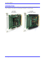

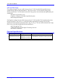
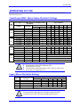
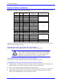

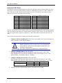
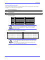
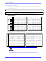

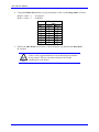
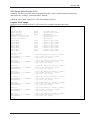
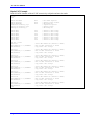
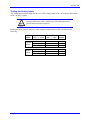
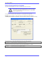
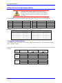


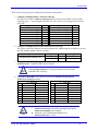
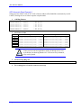
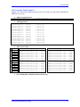
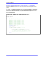
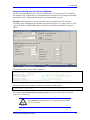


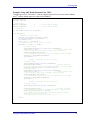


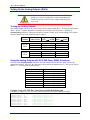
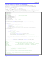
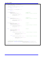
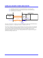
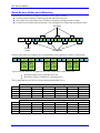
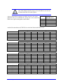
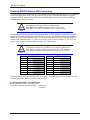
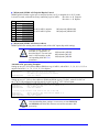
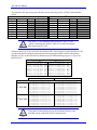

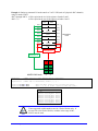
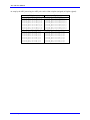
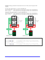
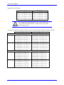
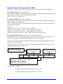

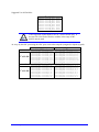
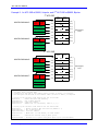
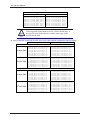
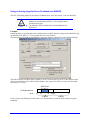
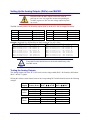
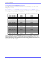
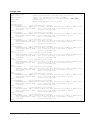
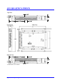
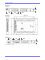
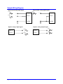

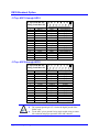
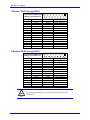
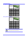
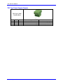
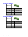
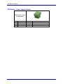

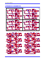
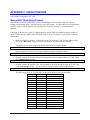
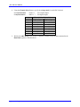
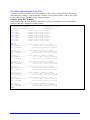
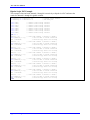


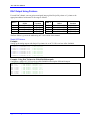
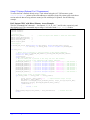

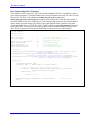


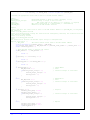


![[DRAFT] DEMO908JL16 User`s Manual](http://vs1.manualzilla.com/store/data/005639706_1-2a84cd2ce2f0b318fdb7aae7896f2a79-150x150.png)