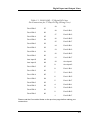
1
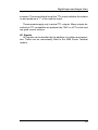
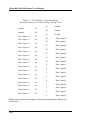
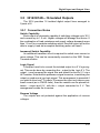
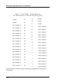
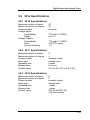
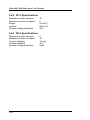
MICROLINK 301x
Digital Inputs and Outputs
User Manual
Biodata Limited
Manual Code: M3000-3.2
Issue Date: December 1998
Information in this document is subject to change without notice.
Updates are listed on our web site at
http://www.microlink.co.uk/techsupp.html
© Biodata Limited, 1990–2005
10 Stocks Street
Manchester
M8 8QG
Tel: 0161–834 6688
Fax: 0161–833 2190
Email: [email protected]
http://www.microlink.co.uk/
Digital Input and Output Lines
Digital Input and
Output Lines
The 301x range provides digital input to the computer and output
control by the computer. It features logic level inputs and outputs, and
switching functions through relays and transistors. The input and
output lines of a 301x are arranged in groups, or ports, of up to 8 lines.
Each port can be either input or output. All ports power-up as inputs. In
the case of relay modules, this means all relays off.
The range consists of 5 modules. Each module has 2 versions, one
having the added advantage of light-emitting diodes to show the state
of the input or output lines. Modules with the display lights have the
suffix D on the module code, for example 3010D. The light is
illuminated when the input or output state is high and corresponds to an
input or output state of 1.
The 3010, 3012, 3013 and 3014 modules have 37-way D type
sockets. If you prefer to make your connections to screw terminals, you
can do so with a 390x module. The 309x modules also provide a range
of extra facilities if components such as resistors or filters are added.
See Chapter 11 for details. The 3011 has screw terminal connections
as standard.
3.1
Microlink 3000 Hardware User Manual
3.1 3010/3010D—32 Digital I/O Lines
The 3010 provides 32 general purpose input and output lines,
arranged as 4 ports of 8 lines.
3.1.1 Connection Notes
Input Voltages
All inputs are high impedance CMOS type. They are TTL and 5 V
CMOS compatible. Input voltages should be within the range 0 to 5 V.
Higher voltages can be dealt with by the addition of resistor networks.
This can be conveniently done on a 3900 Screw Terminal module.
Input protection can be provided in a similar manner.
Contact Closures
You can interface to contact closures using a resistor to tie the input
to either 5 V or 0 V. The contact then switches the line to either 0 or 5 V.
The resistor can be fitted to a 3900 module.
Noisy Inputs
Input Filters can be fitted to a 3900 module if required.
Output Drive
The outputs are TTL and 5 V CMOS compatible. They can drive 15
LSTTL loads. The output drive can be increased by using additional
transistors. These can be fitted to the 3900 module. Currents of 1 amp
can easily be switched.
Power-Up State
The module will power-up as all inputs. If you intend to use the
module to produce control outputs then you might want to define logic
states at power-up. This can be done by resistors which tie the lines to
either 0 V or 5 V. These can be mounted on a 3900 module.
3.2
Digital Input and Output Lines
Table 3.1 3010/3010D - 32 Digital I/O Lines
Pin Connections for 37-Way D Plug (Wiring View)
Port 3 Bit 0
37
Port 3 Bit 2
36
Port 3 Bit 4
35
Port 3 Bit 6
34
Port 2 Bit 0
33
Port 2 Bit 2
32
Port 2 Bit 4
31
Port 2 Bit 6
30
Aux Input 0
29
Aux Input 2
28
Port 1 Bit 0
27
Port 1 Bit 2
26
Port 1 Bit 4
25
Port 1 Bit 6
24
Port 0 Bit 0
23
Port 0 Bit 2
22
Port 0 Bit 4
21
Port 0 Bit 6
20
19
0V
18
Port 3 Bit 1
17
Port 3 Bit 3
16
Port 3 Bit 5
15
Port 3 Bit 7
14
Port 2 Bit 1
13
Port 2 Bit 3
12
Port 2 Bit 5
11
Port 2 Bit 7
10
Aux Input 1
9
Aux Input 3
8
Port 1 Bit 1
7
Port 1 Bit 3
6
Port 1 Bit 5
5
Port 1 Bit 7
4
Port 0 Bit 1
3
Port 0 Bit 3
2
Port 0 Bit 5
1
Port 0 Bit 7
Please read the Connection Notes on the previous page before making your
connections.
3.3
Microlink 3000 Hardware User Manual
3.2 3011/3011D—4 Heavy Duty Relays
The 3011 provides 4 independent change-over power relays. There
is only one port (of 4 bits) and the port can only be an output. The state
of the relays can be read by the computer.
3.2.1 Connection Notes
Relay Type
The relays are the change-over type. When no power is supplied to
the Microlink the Pole of each relay will be connected to its Normally
Closed contact. The Pole of the relay will only switch to the Normally
Open contact when instructed to do so by software.
Inductive Loads
The relay contacts are rated at 10 A 230 V AC for a resistive load. If
the load is inductive (for example a motor or a solenoid) then the rating
must be reduced, because of the large transients that are produced
when inductances are switched. A 0.1 µF capacitor, in series with a
100 Ω resistor, is fitted across each contact. This reduces the size of the
transient.
Power-Up State
On power-up each relay will be connected to its Normally Closed
contact. The Pole of the relay will switch to the Normally Open contact
when instructed to do so by software
Wiring the 3011D
To wire the 3011D remove both the basic 3011 and the display
module. Now unplug the display board from the 3011 and wire up the
3011.
3.4
Digital Input and Output Lines
Figure 3.1 3011 Module
3.5
Microlink 3000 Hardware User Manual
3.3 3012/3012D—8 Reed Relays
The 3012 provides 8 independent change-over reed relays. There
is only one port (of 8 bits) and the port can only be an output, although
the state of the relays can be read by the computer.
3.3.1 Connection Notes
Relay Type
The relays are the change-over type. When no power is supplied to
the Microlink the Pole of each relay will be connected to its Normally
Closed contact. This will continue to be the case after power-up. The
Pole of the relay will only switch to the Normally Open contact when
instructed to do so by software.
Inductive Loads
The relay contacts can switch 200 V DC and 250 mA for a resistive
load. If the load is inductive (for example a motor or a solenoid), then
the rating must be reduced because of the large transients that are produced when inductances are switched. Transient suppression
components can be fitted to the 3900 Screw Terminal mode if required.
Capacitive Loads
A situation that often causes trouble is the switching of capacitive
loads. A high current rushes into the capacitance when it is switched,
often sufficient to weld the relay contacts. (If a relay stops working, but
recovers after being given a sharp tap, then the contact has been
welded.) People often don’t realise when they have a capacitive load.
For instance an open circuit screened cable can present a considerable capacitance. If you suspect that you have this problem then series
resistors can be used to limit the peak current. These can conveniently
be fitted to the 3900 Screw Terminal module.
Power-Up State
Each relay will power-up connected to its Normally Closed contact.
3.6
Digital Input and Output Lines
Table 3.2 3012/3012D - 8 Reed Relays
Pin Connections for 37-Way D Plug (Wiring View)
unused
37
unused
36
N.O. Relay 1
35
N.C. Relay 1
34
N.O. Relay 2
33
N.C. Relay 2
32
N.O. Relay 3
31
N.C. Relay 3
30
N.O. Relay 4
29
N.C. Relay 4
28
N.O. Relay 5
27
N.C. Relay 5
26
N.O. Relay 6
25
N.C. Relay 6
24
N.O. Relay 7
23
N.C. Relay 7
22
N.O. Relay 8
21
N.C. Relay 8
20
19
unused
18
unused
17
unused
16
Pole Relay 1
15
unused
14
Pole Relay 2
13
unused
12
Pole Relay 3
11
unused
10
Pole Relay 4
9
unused
8
Pole Relay 5
7
unused
6
Pole Relay 6
5
unused
4
Pole Relay 7
3
unused
2
Pole Relay 8
1
unused
N.O. = Normally Open, N.C. = Normally Closed
Please read the Connection Notes before making your connections.
3.7
Microlink 3000 Hardware User Manual
3.4 3013/3013D—16 Isolated Inputs
The 3013 module provides 16 isolated digital input lines arranged in
2 ports of 8.
3.4.1 Connection Notes
Input Current
Voltages between 5 and 50 Volts can be directly connected across
the + and – inputs of an isolator. Remember that the input is a LED with
a series 4K7 resistor. This means that with 50 V applied about 10 mA
will flow from the signal source. You can reduce this, if you wish, by
adding series resistance to produce an optimum current of about 1 mA.
Higher Voltages
Adding series resistance also allows larger voltages to be handled.
When doing this you should consider the power dissipation in the
added resistor. The 50 volt limit given above is dictated by the 0.5
Watts that this produces in the 4K7 input resistor. Such resistors can be
conveniently mounted on the 3900 Screw Terminal module.
Reverse Voltages
The inputs are protected against reverse voltages up to 50 V. This
limit is imposed by power dissipation as above.
Input to Input Isolation
Each of the 16 inputs is isolated not only from the main Microlink
circuits but also from the other 15 inputs. This means that the module
can accept signals from several sources which have large standing
voltages between them.
TTL Signals
Logic signals produced by TTL circuits need special consideration.
This is because TTL outputs are poor current sources. This means that
if you connect the + input of an isolator to the TTL signal and the – input
to the signal 0 V, the TTL output will not be able to drive much current
through the LED. TTL outputs are however good current sinks. The
correct way is to connect the isolator + input to +5 V and the isolator –
input to the TTL output. This works well, although it produces a logic
3.8
Digital Input and Output Lines
inversion. This means that a low at the TTL output switches the isolator
on and produces a “1” at the module output.
These remarks apply only to actual TTL outputs. Many outputs described as TTL compatible are produced by 74HC or HCT circuits and
are good current sources.
AC Signals
AC signals can be handled by the addition of rectifiers and capacitors. These can be conveniently fitted to the 3900 Screw Terminal
module.
3.9
Microlink 3000 Hardware User Manual
Table 3.3 3013/3013D - 16 Isolated Inputs
Pin Connections for 37-Way D Plug (Wiring View)
unused
37
unused
36
Port 1 Input 0 +
35
Port 1 Input 1 +
34
Port 1 Input 2 +
33
Port 1 Input 3 +
32
Port 1 Input 4 +
31
Port 1 Input 5 +
30
Port 1 Input 6 +
29
Port 1 Input 7 +
28
Port 0 Input 0 +
27
Port 0 Input 1 +
26
Port 0 Input 2 +
25
Port 0 Input 3 +
24
Port 0 Input 4 +
23
Port 0 Input 5 +
22
Port 0 Input 6 +
21
Port 0 Input 7 +
20
19
unused
18
unused
17
unused
16
– Port 1 Input 0
15
– Port 1 Input 1
14
– Port 1 Input 2
13
– Port 1 Input 3
12
– Port 1 Input 4
11
– Port 1 Input 5
10
– Port 1 Input 6
9
– Port 1 Input 7
8
– Port 0 Input 0
7
– Port 0 Input 1
6
– Port 0 Input 2
5
– Port 0 Input 3
4
– Port 0 Input 4
3
– Port 0 Input 5
2
– Port 0 Input 6
1
– Port 0 Input 7
Please read the Connection Notes on the previous page before making your
connections.
3.10
Digital Input and Output Lines
3.5 3014/3014D—16 Isolated Outputs
The 3014 provides 16 isolated digital output lines arranged in
2 ports of 8.
3.5.1 Connection Notes
Switch Capability
Each output is a transistor capable of switching voltages up to 30 V
and currents up to 1.5 mA. Higher voltages will damage the device. If
the combination of load resistance and supply voltage demands more
than 1.5 mA for a complete switching action, then the output will not be
able to supply it and an incomplete switching action will result.
Increased Switch Capability
An additional transistor circuit is required to switch more current or
more voltage. This can be conveniently mounted on the 3901 Screw
Terminal module.
Logic Signal
A frequent need is to convert the isolated output to a 5 V logic signal. This can be done by connecting the – output to the logic 0 V. The
output + now becomes the signal line and should be tied to 5 V via a
4K7 resistor. Note that this produces a signal inversion, ie switching the
output on produces a low logic signal. This arrangement is essential if
you wish to drive true TTL inputs. If however the input only takes a very
small current (as in CMOS units), then the resistor can be placed between – output and 0 V, with the + output connected to 5 V. This
arrangement avoids the inversion.
Reverse Voltage
The outputs are not protected against the application of reverse
voltages.
3.11
Microlink 3000 Hardware User Manual
Table 3.4 3014/3014D - 16 Isolated Outputs
Pin Connections for 37-Way D Plug (Wiring View)
unused
37
unused
36
Port 1 Output 0 +
35
Port 1 Output 1 +
34
Port 1 Output 2 +
33
Port 1 Output 3 +
32
Port 1 Output 4 +
31
Port 1 Output 5 +
30
Port 1 Output 6 +
29
Port 1 Output 7 +
28
Port 0 Output 0 +
27
Port 0 Output 1 +
26
Port 0 Output 2 +
25
Port 0 Output 3 +
24
Port 0 Output 4 +
23
Port 0 Output 5 +
22
Port 0 Output 6 +
21
Port 0 Output 7 +
20
19
unused
18
unused
17
unused
16
– Port 1 Output 0
15
– Port 1 Output 1
14
– Port 1 Output 2
13
– Port 1 Output 3
12
– Port 1 Output 4
11
– Port 1 Output 5
10
– Port 1 Output 6
9
– Port 1 Output 7
8
– Port 0 Output 0
7
– Port 0 Output 1
6
– Port 0 Output 2
5
– Port 0 Output 3
4
– Port 0 Output 4
3
– Port 0 Output 5
2
– Port 0 Output 6
1
– Port 0 Output 7
Please read the Connection Notes on the previous pages before making your
connections.
3.12
Digital Input and Output Lines
3.6 301x Specifications
3.6.1 3010 Specifications
Maximum number of inputs
Maximum number of outputs
Power-up state
Voltage Inputs
Compatibility
Range
Voltage Outputs
Compatibility
Drive
Current switching
32
32
all inputs
TTL and 5 V CMOS
0 to 5 V
TTL and 5 V CMOS
15 LSTTL loads
1A
3.6.2 3011 Specifications
Maximum number of inputs
Maximum number of outputs
Power-up state
Relay type
Operating time
Release time
Contact rating
0
4
normally closed
change-over
8 msec
2.5 msec
10 A at 30 V DC or 230 V AC
3.6.3 3012 Specifications
Maximum number of inputs
Maximum number of outputs
Power-up state
Relay type
Operating time
Release time
Contact rating
0
8
normally closed
change-over
1 msec
1 msec
250 mA at 200 V DC,
3 W non-reactive
3.13
Microlink 3000 Hardware User Manual
3.6.4 3013 Specifications
Maximum number of inputs
Maximum number of outputs
Range
Isolation
Reverse voltage protection
16
0
0 to 50 V
240 V AC
50 V
3.6.5 3014 Specifications
Maximum number of inputs
Maximum number of outputs
Current switching
Voltage switching
Reverse voltage protection
3.14
0
16
1.5 mA
30 V
None