1
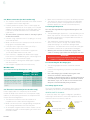
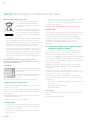
UltraClean 3 User Manual
Washer Disinfector Dryer
Bench Top/Under Bench Models
884100A
2
Instructions for use
Please read these instructions before using the
UltraClean 3.
Keep these “Instructions for use” in a safe place
close by the unit for future reference.
Service Helpline: Telephone: 01254 844 116
e.mail: [email protected]
The Prestige Medical Customer Service team is available
to provide advice and assistance during normal office
hours. To avoid delays when making contact, please have
the Serial Number at hand.
For additional information visit
www.prestigemedical.co.uk
UK Customers
Prestige Medical Limited
East House, Duttons Way,
Shadsworth Business Park,
Blackburn BB1 2QR
Tel : +44 (0) 1254 682 622
Fax : +44 (0) 1254 682 606
Overseas
Customers
Contact your local
distributor. In case of
doubt contact Prestige
Medical.
Thank you for choosing the Prestige Medical UltraClean 3.
The installation, maintenance and operating instructions
given in the following pages have been prepared to ensure
the long life and high performance of the appliance. Please
follow the instructions carefully.
WARNING!
Refer to the instrument manufacturer to ensure the instrument’s
suitability for cleaning in a washer disinfector.
WARNING
IT IS THE USER’S RESPONSIBILITY TO OPERATE THIS
WASHER DISINFECTOR IN A SAFE MANNER AND IN
ACCORDANCE WITH THE INSTRUCTIONS SET OUT
IN THIS MANUAL AND ONLY TO USE THIS WASHER
DISINFECTOR FOR ITS INTENDED PURPOSE.
NON-OBSERVANCE, EVEN IN PART, OF THE
RULES INDICATED INTHIS MANUAL WILL
CAUSE THE PRODUCT GUARANTEE TO
BECOME INVALID AND RELIEVES PRESTIGE MEDICAL
OF ANY RESPONSIBILITY..
www.prestigemedical.co.uk
[email protected]
Model no.
Date of purchase
Serial no.
0086
Prestige Medical Limited
East House, Duttons Way,
Shadsworth Business Park,
Blackburn BB1 2QR
Tel : +44 (0) 1254 682 622
Fax : +44 (0) 1254 682 606
www.prestigemedical.co.uk
[email protected]
884100A
Registered in England
Reg No. 2826793
3
Contents
Section
Page
1.
General rules
4
1.1
Safety recommendations
4
1.2Recommendations to ensure high quality perfomance
4
2.
Installation (for the installer only)
5
2.1
Positioning the machine
5
2.2
Water connection (for the installer only)
6
2.3
Electrical connection (for the installer only)
6
2.4
Detergent dispenser
6
2.5
Connecting the discharge pipe
6
2.6
Safety signals used
6
2.7
Staff training
7
2.8
Indication of sound level
7
3.
Using the machine (for the user)
8
3.1Checks
8
3.2
8
Opening and closing the door
3.3Preparation
8
3.4Functions
8
3.5
Treatment of turbines, straight and
angular hand pieces (opposed angles)
8
4.
Control panel and symbols used
9
4.1
Washing cycles
9
4.2
Details of the electronic PCB
9
4.3
Control panel / decal and buttons
9
4.4
Front panel decal
9
5.
Machine status
10
5.1Wait
10
5.2Cycle
10
5.3
Shut down
10
6.
Special features
10
6.1
Power failure
10
6.2
Reset procedure.
10
7.
Alarms and events list
8.
PC interface
10-11
12
9.Maintenance
12
10.Specification
12
884100A
4
Section 1: General rules
It is important to keep this instruction manual with the
machine for future reference. If the machine is sold or
transferred, the manual must be handed over to the new
owners or user in order for them to become acquainted
with its functioning and the relative warnings. The purpose
of the warnings is to safeguard the user in compliance
with directive 93/42 with incorporated in the “Harmonised
Technical Product Standards” EN 61010-1 and EN 610102-040.
- The water in the tank is not drinking water.
Read the warnings carefully before installing and
using the machine.
- The acoustic pressure of the machine is below 70dB (A).
1.1 Safety recommendations
- Do not lean on the door and do not use it as a step.
- The machine reaches a temperature of 95°C during the
work cycle: take great care to avoid burns.
- Do not wash the machine using high-pressure jets of
water.
- Disconnect the machine from the electrical supply before
carrying out maintenance work.
1.2 Recommendations to ensure high
quality performance.
- If the new machine appears to be damaged, contact the
retailer before starting it.
- When the machine is running do not interrupt
the cycle since this jeopardises disinfection.
- Qualified, authorised persons must carry out any
modification of electrical and hydraulic systems
necessary to install the machine only.
- Check periodically using chemical indicators to
ensure correct disinfection.
- This machine must be operated by trained persons only;
- The machine was designed for washing and disinfecting
kidney bowls, drainage collection bottles and other
receptacles used in health practices, hospital wards,
nursing homes, old-peoples’ homes and dental
surgeries. A special rack is supplied for dental turbines
and hand pieces.
- Any use other than that for which the machine was
intended could be dangerous and may invalidate the
warranty.
- Use recommended detergents and chemical additives
only. The use of other products may damage the
machine.
- Recommending chemical additives does not make
the manufacturer responsible for any damage to the
materials and objects treated.
- Follow the manufacturer’s indications when using
chemical products and use them for the foreseen use
only.
- Unauthorised repairs or modifications to the machine will
invalidate the warranty.
- The machine was designed for use with water and
chemical additives. Do not use organic or other types
of solvent as this may result in the risk of explosion or
the rapid deterioration of certain machine parts.
- Technical assistance for this washer disinfector should
be obtained from qualified and authorised persons only.
- Residues of solvents or acids, particularly “hydrochloric
acid”, can damage steel. Contact should be avoided.
- Only an authorised person should install the equipment.
- Use original accessories only.
- Do not install the equipment in rooms where there is the
risk of explosion.
- Never use soap powder.
- Do not expose the equipment to intense cold.
- Never use chemical products based on chlorides
(bleaches, sodium hypochlorite, hydrochloric acid and
so on). These kinds of chemical detergents irreparably
damage the machine and jeopardise the integrity of
materials and objects treated.
- The electrical safety of this washer disinfector is only
guaranteed if it is connected to an efficient earth system.
- Take great care when handling detergents and additives:
avoid contact, wear gloves and act in compliance
with the safety recommendations indicated by the
manufacturer of the chemical products.
- Do not inhale the fumes produced by chemical products.
WARNING!
The chemical products are an irritant for the eyes, in case of
contact rinse thoroughly with plenty of water and consult a
doctor. If these products come into contact with the skin,
rinse with plenty of water.
884100A
- Never use foaming detergent.
The manufacturer declines all responsibility for
personal injury or material damage resulting from
the non-observance of the above rules.
The non-observance of these rules &
recommendations will invalidate the warranty.
5
Section 2: Installation (for the installer only)
2.1 Positioning the machine
All the packaging materials can be recycled.
• Open the packaging carefully.
• Do not overturn the machine as this may cause
irreparable damage.
• Cut the strap or open the box and remove the expanded
polystyrene corner guards.
• Remove the box followed by the nylon bag.
• Caution: the bag represents a serious hazard for children
and should be disposed of immediately.
• Place the machine on the work surface and level it by
adjusting the feet.
Built in limits: Bench Top
Built in limits: Under Bench
884100A
6
2.2 Water connection (for the installer only)
• Make sure that the electrical systems are efficiently earthed.
• This machine should be connected to the water network
in compliance with current legislation
• The terminal on the rear of the machine and identified
by the relative symbol is for equipotential connections
between appliances (see rules for electrical plants).
• For best performance, both a hot & a cold supply are
required. (In the absence of a hot supply, use a suitable
adapter to connect both inputs to the cold supply. The
customer should be advised that this will extend the
cycle times.)
• The non-return system for water is already in place
inside the machine.
• Connect using stopcocks with ¾” couplings in an easily
accessible position.
2.4 Detergent dispenser
Use only Prestige Medical approved detergents and
chemicals
• The liquid detergent dispenser is a standard fitting on the
bench top machine. The machine is fitted with a 500 cl
detergent compartment in the panel below the door as
part of standard supply.
• If the pressure is higher than 5 Bars (500 KPa) a
pressure reducer must be installed.
• The under bench machine features a lower cabinet
which can be used for storage. The cabinet contains
a pipe terminating in an automatic detergent feed
mechanism. The feed mechanism at the end of the pipe
should be inserted into an open bottle of detergent.
• If the average hardness of the water is higher than
10°FR, decalcified water must be used.
• Warning: the machine is fitted with a gauge that
sends a warning signal when the detergent runs out.
• Make sure that the mains water pressure falls within the
range given in the below table.
• Each machine is supplied with rubber water supply
hoses with 3/4” threaded fittings plus a discharge hose.
• Connect the pipes to the water supply.
• Do not shorten or damage the rubber pipes supplied
with the machine.
• Use the pipes supplied with the machine only.
Min/Max table
(for authorised and qualified persons only)
WARNING!
To ensure the efficiency of the dispenser pumps for chemical
products, it is important to service them regularly.
2.5 Connecting the discharge pipe.
• The discharge pipe connection should be checked
carefully.
• A 28mm discharge fitting is present on the back of the
machine.
Pressure
Minimum
kPa (Bar)
Maximum
kPa (Bar)
• Use a discharge pipe suitable for organic and
chemical materials and hot liquids.
Static Pressure
250 (2·5)
500 (5·0)
Dynamic Pressure
200 (2·0)
400 (4·0)
Hardness of supply water
0ºFr
+10ºFr
Temperature of cold water
supply
+5°C
+15°C
• Caution: If the discharge pipe is clogged take great
care when processing the water and avoid contact
with hands, eyes, etc. In the case of contact rinse
the parts concerned with plenty of water.
2.3 Electrical connection (for the installer only)
Power supply cable: It is compulsory for the retailer installer to adapt the insulation class of the power supply
cable to suit the working environment in compliance with
Current Technical Regulations.
• The electrical connection must be carried out in
compliance with current technical regulations.
2.6 Safety signals used
To ensure safe operation, the following safety signals (as
specified by 92/58 EEC) are attached to the machine.
GENERIC SAFETY SIGNALS:
In particular, labels with signals of obligation, prohibition
and danger contained in this manual and pertinent to this
machine and most commonly used are:
Electrical Risk
• Make sure that the mains voltage reading corresponds
to the voltage indicated on the machine plate.
• An omnipolar magneto thermal switch sized to suit the
absorption and with a contact opening of at least 3mm
must be installed.
884100A
Warning! See annex
documentation
Caution Hot
Surface
7
The employer is required to carry out a health and safety
risk assessment prior to operating this machine for the first
time. Suitable protective equipment as deemed necessary
by the risk assessment should be provided.
The responsible authority will be responsible for operation
of all command, control and safety devices in the machines
of the system. He shall carry out scheduled verification of
those devices in order to ensure their continued operation
over time.
2.7 Staff training
Ac
INDIVIDUAL SAFETY WEAR:
The INSTALLATION ENGINEER will provide instructions for
use of the machine during the start-up phase to MACHINE
OPERATORS and MAINTENANCE TECHNICIANS for their
areas of responsibility. It will be the duty of the EMPLOYER
to check that the degree of staff training is suitable for
assigned duties.
2.7.1 Staff qualification
Depending on the difficulty of certain installation operations,
and of the operation and maintenance of the system,
professional profiles are identified as follows:
Is
INSTALLATION and REPAIR TECHNICIAN:
Specialized installation and maintenance staff capable
of carrying out all machine positioning and installation
operations, connection of various systems and machine
start-up at the client’s place of business, as well as all
routine and special maintenance operations. This operator
is responsible for training staff for machine operation and for
testing the machine.
As RESPONSIBLE AUTHORITY FOR THE MACHINE
IN THE WORKPLACE:
Specialized staff assigned to the verification of safety
devices and procedures for proper use of the machine in
complete safety.
The responsible authority is personally responsible for
training courses for staff assigned to machine operation
and maintenance. He must ensure that staff assigned to
operation has acquired all information required for use and
routine maintenance of the machine, registering attendance
and documenting comprehension tests.
MACHINE OPERATOR:
Skilled personnel assigned to machine operation. The
machine operator must be fully trained in all of the
machine’s command and control devices.
When trained, the operator should be capable of executing
the following tasks:
• Commissioning and start-up of the machine;
• Loading and unloading of material to be washed in the
baskets;
• Operation of the machine in the various possible working
modes, such as the start of various programmed wash
cycles.
• Programming and setting data from the operator panel,
adjustment of single control devices during working
phases, starting or resetting of work functions.
• In addition, the machine operator must, by making use
of all required individual protection gear and following
adequate safety measures, be capable of performing
some routine maintenance such as cleaning inside the
machine, cleaning clogged filters, and disposing of
pollutant waste materials produced during working.
2.8 Indication of sound level
The value shown refers to the measurement obtained on
a machine of the same type as that covered herein and
measured with an instrument at a height of 1.6 m at a
distance of 1 m from the AVERAGE SOUND PRESSURE
LEVEL: 52 dB (A)
The responsible authority must have a perfect
understanding of all command, control and safety devices
of the machine. He must inform all personnel assigned to
machine operation and maintenance of the instructions
concerning safety standards, the actions to be avoided and
the first aid interventions connected with use of the machine
and the chemical wash agents it contains.
The responsible authority must be aware of all correct
procedures for carrying out in absence of all danger all
operation and maintenance of the machine, as well as
all procedures for disposal of any residual pollutants and
manufacturing wastes. He must always be present during
extraordinary or routine maintenance and give his approval
to proceed to staff assigned to operation or to personnel
assigned to routine or special maintenance.
884100A
8
Section 3: Using the machine (for the user)
General information for the user
• D
o not dispose of this equipment
as miscellaneous solid municipal
waste, but arrange to have it collected
separately.
• T
he re-use or correct recycling of the
electronic and electrical equipment
(EEE) is important in order to protect
the environment and the well being of
humans.
• In accordance with European Directive WEEE 2002/96/
EC, special collection points are available to which to
deliver waste electrical and electronic equipment and the
equipment can also be handed over to a distributor at
the moment of purchasing a new equivalent type.
• The public administration and producers of electrical
and electronic equipment are involved in facilitating the
processes of the re-use and recovery of waste electrical
and electronic equipment through the organisation of
collection activities and the use of appropriate planning
arrangements.
Unauthorized disposal of waste electrical and
electronic equipments is punishable by law with
the appropriate penalties.
3.1 Checks
Ensure that there are enough chemical
additives present and top up the tanks
if necessary.
Detergent is placed in the compartment
at the front of the unit (bench top
version).
Check the water supply is connected and turned on.
3.2 Opening and closing the door
The machine is fitted with an electrical door lock to prevent
access during a cycle.
If for some reason you need entry to the machine during
a cycle then you need to abort the cycle by pressing the
STOP button.
When opening the door care must be taken since items in
the machine may be hot.
The entire wash cycle must be repeated.
3.3 Preparation
• Place the items to be washed inside the machine and
position them carefully on the holder and in the rack.
• Items should not overlap.
• Receptacles should be positioned so that liquids can
flow out easily.
884100A
• Tall or heavy items should be placed towards the middle
of the rack if possible to facilitate washing.
• Make sure that nothing is blocking the rotor arms and
they are free to rotate.
CAUTION: The maximum load for each cycle is 8 Kilos.
3.4 Functions
Place the items to be washed in the relative tray positioning
them carefully and follow the instruction that follows. The
control panel with display is illustrated in the diagram.
This panel makes the machine easy to use as it indicates
the stage of the cycle in progress, the maximum
temperature reached during disinfection and fault
messages.
3.5 Treatment of turbines and straight and angular
hand pieces (opposed- angles)
Your machine is equipped with the capability of washing
eight hollow instruments, that need to be washed and
thermo disinfected both internally and externally.
The basket is equipped with special accessories suitable for
inserting the hand pieces. These supports are made in two
parts, screwed together, between, which is a special filter to
protect the hand piece.
Supplied with the unit is a bag of rubber inserts. These
come with two different diameters for use with different
hand pieces.
We recommend washing the filters in the fitting for
supporting the turbines and hand pieces on a weekly basis
or replace when heavily contaminated.
The following operations should be performed for the
correct treatment of the turbines and straight and angular
hand pieces:
- Prewash with cold water, to eliminate residues of blood
and saliva.
- Wash, adding liquid detergent
- Thermo disinfection.
Precautions.
Micro-motors cannot be subjected to thermo disinfection
treatment.
Never use powder detergents.
9
Section 4: Control panel and symbols used
4.1 Washing cycles
QUICK CYCLE
P1
STANDARD CYCLEP2
TEST CYCLE
For lightly soiled items
For other soiled items
P3For compliance, protein and soil residue checks
Switch Prog. Cycle
1
2
3
B7
Dose
B8
Dose
B9
Dose
Pre-wash
QUICK
1minute
None.
STANDARD 4minutes @ 28ºC.
None.
TEST CYCLE 4minutes @ 28ºC.
None.
Main Wash
Rinse
Disinfection
Drying
3minutes @ 40ºC.
60mls detergent.
8minutes @ 58ºC.
60mls detergent.
8minutes @ 58ºC.
60mls detergent.
1minutes
None
2minutes @ 30ºC.
None
30seconds
None
2minutes @ 85ºC.
None
1minute @ 90ºC.
None
1minute @ 90ºC.
None
5minutes
None
15minutes
None
None
None
The complete cycle time is not the sum of these times. On each cycle there is a time to drain and a time to fill/heat the water.
These will vary according to the supply temperature and pressure.
4.2 Details of the electronic PCB
Buttons
The electronic card was designed for the
control of the type of machine described in
this manual.
There are 7 button/switches as shown
on the next page:
The electronic card was designed following
the indications given in the standards below:
EN 60335 low voltage
EN 50081 -1 EN 50082-1 general
EN 55014emissions
EN 55104immunity
4.3 Control panel / Decal and buttons
Display
- Displays the various programmes,
stages, temperatures and any machine
faults.
- During “Wait”, the type of programme
selected is displayed.
- After pressing Start, the display indicates
the temperature of the washing water.
- If a fault occurs the display indicates the
type of fault.
LEDS.
There are eight LED’s as shown opposite:
1. Yellow ‘Start’ LED
2. Red ‘Stop’ LED
3. A flashing red LED to indicate
disinfection not complete.
4. A green LED to indicate cycle finished.
4.4 Front panel decal
P1
Switch (C)
Selects “short + detergent” cycle
5
P2
Switch (D)
Selects “standard + detergent” cycle
C
P3
Switch (E)
Selects Test cycle
D
PRG
Switch (G)
Scrolls between programmes.
DRYING Switch (F)
This option is not used
Start
Switch (A)
Starts the selected cycle.
5
1
2
A
B
3
5
4
E
6
F
G
Stop
Switch (B)
This interrupts the cycle in progress,
the card interrupts the process,
displays a message indicating that
disinfection did not take place, keeps
the door locked and if necessary
indicates a high temperature inside
the chamber. To return the machine to
normal conditions the reset procedure
must be carried out (see page 10).
PRG
Switch (G)
If pressed for 5 seconds, allows
access to the menus.
5. Three yellow LEDs to indicate which
programme is selected.
6. A yellow LED to indicate drying selected.
884100A
10
Section 5: Machine status
Section 6: Special features
When the power to the machine is interrupted and then
restored, the machine memorises the status it was in at
the time power was lost. When the power is restored the
machine normally returns to “Wait” mode.
6.1 Power failure
5.1 Wait
When power is restored following a power failure with a
cycle in progress, the card shuts down the machine (power
failure), indicates that a cycle has been interrupted and
waits for the reset procedure to be carried out.
The machine is ready to start a cycle.
The diagnostics are active.
5.2 Cycle
Pressing the Start button allows cycle mode to be entered,
this command is only accepted if the machine is in wait
mode and the door is closed.
The cycle carries out the required stages with diagnostics
and regulators active. The display gives information
concerning the stage in progress.
5.3 Shutdown
The diagnostics have detected a fault that causes the
machine to shutdown, the cycle is suspended and the door
remains locked. The fault is indicated on the red led and the
user interface is ready for the door release sequence and
the Reset procedure to restore the machine to Wait (see
reset procedure).
When power is restored following a power failure during
Preparing, Wait or Shutdown, the card returns to the
previous programme.
6.2 Reset procedure
In the event of a Shutdown or when the stop switch is
pressed with a cycle in progress, the door remains locked.
To open the door the door release sequence must be
carried out from the keyboard as follows:
1. Press the STOP and START switches together and keep
pressed for 3 seconds.
2. Press the standard program key (P02) followed by the
short programme switch (P01)
3. The machine is reset and returns to standby.
N.B.: If the machine shutdown persists due to a fault in one
of its components (e.g.: faulty probe, unsuitable levels, etc.),
the door is released and the machine remains inactive. Seek
technical assistance.
Section 7: Alarms and events list
UltraClean 3 / Warning list
Display message.
Description.
Lack chemical 1
Lack of chemical 1 (Acid detergent).
Open door
It points out that a door is open.
Wait
Generic warning that signals to the operator that he has to wait before starting any new action.
Close the door!
It warns to close any door/doors that are open during the door initialisation procedure.
These warnings function if Parameter P3.27 is set.
UltraClean 3 / Historical events
Events
Display message
Description.
1 to 61
Same as alarm list
See alarm list
90
OK
Cycle completed successfully.
91
NO DISINFECTION
Cycle has been interrupted.
884100A
11
Section 7: Alarms and events list (continued)
UltraClean 3 / Alarms list
ALARMS
Display Message
Description
1
Power Failure
It shows power failure during a cycle.
2
Loading door open
Loading door open during a cycle.
3
Unloading door open
Unloading door open during a cycle.
4
Block loading door
Loading door blocked.
5
Block unloading door
Unloading door blocked.
6
Doors problem
Incorrect door position (both open or unblocked).
7
Unblocked load door
Loading door problems: a) Overtime lock door Ref. P6.05
b) During block door, the door has opened.
8
Unblock unload door
Unloading door problems: a) Overtime lock door Ref. P6.05
b) During block door, the door has opened.
9
Load door time out
Overtime unlock loading door Ref.P6.14
10
Unload door time out
Overtime unlock unloading door Ref.P6.14
11
Cold water lack
Overtime Cold water loading level P6.32
15
Mixed Cold + Demi. Lack
Overtime Cold + Demi. water loading level P6.35
17
No chemical 1
Lack of chemical 1
23
Drain time out
Overtime minimum tank level during the drain. Ref.P6.04 & P6.031
24
Blower
Blower switch on with pressure switch open
27
Lim.°C tank probe
Tank temperature exceeds maximum of 102°C
28
Dryer Probe
Drying probe exceeds 162°C.
30
Tank probe
Failed tank probe 1.
31
2nd tank probe
Failed tank probe 2
34
Temp.Check
It appears when:
a) Tank temperature over value P7.11
b) Tank temperature probes diff > 1°C Ref.P7.04
35
Load panel
No connection from main board to loading switch board.
36
Unload panel
No connection from main board to unloading switch board.
37
Can serial
No connection from main board to 2nd.board (Canbus).
39
No tank heat
During tank electrical heating phase, the temperature does not
increase of 1°C in the prefixed time given by P6.01
46
Pressure switch pump
The washing pressure is below lower limit.
47
Impulse error Product 1
The flow meter product 1 had counted an impulse number different
from the set point P7.21
55
Conductivity probe
Conductivity first probe failure
56
High conductivity
For 3 times high conductivity.
58
No tank heat
During tank steam heating phase, thee temperature does not
increase 1°C in prefixed time (P6.01)
60
Time
Phase time much too long.
61
Steam heating
The machine is set to steam heating and one input (19 or 27) is open.
85
Treatment exceeds temperature limit.
Temperature exceeded set point by greater than the value set in Par
7.01
884100A
12
Section 8: PC interface
The card has a communication channel RS232 with Modbus
protocol. The channel can be used to access historical data
records by setting the printer / hyper terminal to: Baud Rate:
2400
Handshaking:
X ON X OFF
Data bits:
8
Parity:
None
Section 9: Maintenance
It is advisable to carry out a general check-up and
to clean the appliance regularly, particularly if the
supply water is very hard.
WARNING!
It is necessary to have the machine checked and maintained at
regular intervals in order to ensure perfect operation.
THE MEMBRANE PIPE INSIDE DOSING PUMP MUST
BE CHANGED EVERY 12 MONTHS.
Cleaning the nozzles
Remove the washing arms.
Remove scaling.
Cleaning the external structure
Use mild detergents only, do not use abrasive detergents
or solvents and/or thinners of any kind.
Your retailer can recommend suitable products.
Particular attention should be paid to heating
element and the probe of thermostats
Section 10: Specifications
WARNING:
• Do not clean the machine outside with high pressure
water.
10.1 Dimensions
• Please contact the retailer that supplies your cleaning
products for details of recommended methods and
products for sanitizing the machine regularly.
• The machine has a safety thermostat that shuts down
the power supply to the heating elements in the event
of overheating.
Width 560 mm
Depth (door closed)
575 mm
Depth (door open) 865 mm
Height 555 mm/800mm
Bench Top/Under Bench
10.2 Service connections
To re-start the appliance the fault that caused
overheating must be corrected.
Drain Connection 25 mm Dia
Cold Water Supply (min/max)
1.0- 5.0 Bar
Every 2 months:
Water Connection 3/4” BSP
Even if the supply water is soft, the high working
temperatures may cause limescale to build-up. Apart from
damaging the resistors, limescale can also clog the nozzles
in which case the correct tank temperature for sterilization
may not be reached. It is advisable to run a cycle with
Prestige Medical De-Scaler every 2 months to ensure
optimal performance.
Maximum Water Capacity 24L/min @ 2Bar Press
Water Supply Temperature
10ºC – 15ºC
Water Hardness
100.00PPM (10 ºf)
Electrical Supply 230v 50Hz / 2.95Kw
Electrical Connection 13A - 3 Pin Plug
Pump Power 150 W
Every 12 months:
10.3 General
- Clean the diaphragms of solenoid valves and replace if
necessary;
Ambient Room Temperature
(min/max) +5ºC / +40ºC
- Clean the thermostat probe
Noise Level 52dB (A)
884100A