1
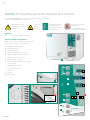
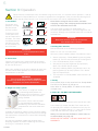
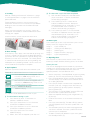
Alpha User Manual
22 litre Non Vacuum (N) Autoclave
274454A
2
Instructions for use
Please read these instructions before using the
autoclave.
Keep these “Instructions for use” in a safe place
close by the unit for future reference.
Service Helpline: Telephone: 01254 844 116
(UK only - 24hr)
e.mail: [email protected]
Prestige Medical Service staff are available to provide
advice and assistance during normal office hours. To avoid
delays when making contact please have the units Model
and Serial Numbers at hand. These can be found on the
rating plate located at the rear of the unit or on the bezel
inside the door.
For additional information visit
www.prestigemedical.co.uk
UK Customers
Prestige Medical Limited
East House, Duttons Way,
Shadsworth Business Park,
Blackburn BB1 2QR
Tel : +44 (0) 1254 682 622
Fax : +44 (0) 1254 682 606
Overseas
Customers
Contents.
Section
Page
1Introduction
3
2
4
Operating Symbols, Displays
and Controls
3Operation
6
4
Essential Information
8
5
Routine Care and Maintenance
9
6
Trouble Shooting
10
7
Recovery Sequence
11
8
Additional Information
12
9Specification
13
10
Cycle Profiles
14
11
Water Quality
15
12
Loading the Autoclave
15
13Warranty
15
14
16
Daily Record Sheet
Contact your local
distributor. In case of doubt
contact Prestige Medical.
www.prestigemedical.co.uk
[email protected]
Destination Kit
Date of purchase
Model no.
Vessel rating plate (duplicate)
0086
Serial no.
Prestige Medical Limited
East House, Duttons Way,
Shadsworth Business Park,
Blackburn BB1 2QR
Tel : +44 (0) 1254 682 622
Fax : +44 (0) 1254 682 606
www.prestigemedical.co.uk
[email protected]
274454A
Registered in England
Reg No. 2826793
3
Section 1: Introduction
Thank you for choosing the Prestige Medical Alpha
Autoclave. This machine is fitted with sophisticated control
software and will automatically adjust the cycle time
dependent on the mass of load used. This will ensure the
optimum sterilizing and drying conditions for all loads.
Non-vacuum cycles use the thermodynamic air
displacement system and employ an ‘open door’ drying
system.
An “Auto-cycle start” option is included which allows the
user to programme the time of day at which the selected
cycle should start.
Before unpacking, refer to the “Manual Handling”
section on page 12, section 8.
Whilst unpacking check the unit for transit damage.
If damage is found, please report this to the shipping
agent immediately, in writing, and then notify your dealer.
Product contents comprise of the following: • Autoclave with internal furniture.
• Instructions for Use and warranty card.
• Performance Test Certificate and Certificate of
Conformance for pressure vessel (all UK models).
• Installation sheet.
• Written Scheme of Examination (UK models).
• Waste water container.
All Customers, when you receive your Alpha
autoclave ensure that you complete and return your
Warranty Registration Card.
Types of load and loading.
Alpha autoclaves are designed to sterilize instruments,
utensils and other items as defined by the European
Standard EN13060.
The autoclaves operate automatically with 134°C and
121°C sterilizing temperatures (with or without drying).
For a full list of sterilizing cycles and times refer to Section
10.
WARNING!
Refer to the instrument manufacturer to ensure the instruments
suitability for autoclaving and the maximum temperature they
can withstand.
A “responsible person” must qualify other loads as
suitable. Refer to “Additional Information” in Section 8.
Refer to “Technical Specifications”, Section 9, for the
maximum instrument load for the autoclave.
All instruments must be cleaned appropriately prior to
sterilizing.
When placing items on a tray ensure that they do not
touch each other and that the load does not touch other
trays or the chamber in any way.
Always use the lifting device when removing trays from the
autoclave as they may be hot.
Do not use an unprotected hand to hold hot trays.
274454A
4
Section 2: Operating symbols, displays and controls
The following descriptions refer to the symbols, controls and displays
used on the ALPHA range of autoclaves.
IMPORTANT: Read
Operating Instructions
before use.
Fill water tank when
LED illuminated
(Maximum fill level is
S3 opposite).
Hot parts.
Do Not
Touch.
Do not use tap water
(S2 below).
For acceptable water
quality refer to Section 13.
Symbols:
S1
Cycle status graphic segments.
General controls / Operations:
Note: The function is selected when the LED
adjacent to the button is illuminated.
A Standby / Ready button.
B Cycle start button.
C Door open button.
D Select time/date/cycle counter.
E Adjust time/date settings (E1/E2)
F Select Non-vacuum cycles.
G Select “Additional drying”.
K
H Fuses (located behind access panel).
I Printer socket
J Main door (not shown)
A
K Fresh water tank drain.
L Water fill.
L1
L Air filter.
D
N
M Rating plate.
H
L2
E1
I
E2
S2
L3
L
M
L6
F
S3
S1
L4 L5
G
B
C
274454A
L7 L8
5
Cycle controls.
Examples below show:Press H to select “Additional Drying
Additional drying.
Non-vacuum cycle for unwrapped
solid instruments, without drying.
AFTER EVERY CYCLE THE UNIT RETURNS TO THE
DEFAULT CYCLE.
Default for Non-Vacuum units
Non-vacuum cycle for unwrapped solid
instruments, with drying.
The 121°C or 134°C led will be illuminated to show
which cycle is selected.
Display Options.
L1 Display for “Time” “Date”
& “Cycle counter”. The
normal display mode is
time. The date or cycle
counter can be selected
by pressing the button D
L2
adjacent to the display.
The selection is valid until
a cycle is completed or
until the unit is returned to
standby mode, at which
L3
point the display will revert
to the current time.
L1
134°C. Non-vacuum cycle without drying.
134°C. Non-vacuum cycle with drying.
L2 Display for “Temperature”
L3 Display for “Pressure”.
The following show the cycle status:
L4 Cycle started.
L6
L4
L5
L5 Heating and air bleed.
L7
L8
L6 Sterilizing.
L7 Depressurisation / drying.
L8 Cycle complete.
274454A
6
Section 3: Operation
Please take time to read these instructions before using the autoclave. It is essential that the operator is correctly
trained and a “Responsible Person” has been assigned for the management of the autoclave. By following these
simple step-by-step instructions you can ensure your instruments are correctly sterilized every time.
1. Installation.
Ensure the unit is
placed on a strong,
flat, level & heat
resistant surface.
To check if the unit
is level, pour half a
cup of water into the
chamber. The water
should flow towards
the hole at the rear
of the chamber, not
out of the front.
WARNING!
The autoclave is heavy; at least two people will be needed
to lift it.
Note: Before using for the first time, and after
emptying, always add cold (tap) water until the level
reaches the minimum level mark.
The waste water container can be located in any
convenient place provided it is at a lower height than the
autoclave, although care should be taken that it cannot be
knocked over.
WARNING!
Waste water and steam condensing coil may be hot.
Care should be taken at all times.
4. Setting date and time.
Date and time are set in the following sequence.
Note: This unit uses a 24 hour clock.
Year (tens): Year (hundreds): Month: Day: Minutes: Hours.
• Set the autoclave in “Ready Mode” by pressing ready
button (A). The LED next to button (A) will then go out.
2. Connection.
Plug the unit into the mains outlet socket of the correct
type & rating. See rating plate (O). Push the on/off switch
on the front of the unit.
• Press and hold button (D) for 5 seconds.
After a few seconds the LED next to button (A) illuminates
and the internal heater operates to control the internal
temperature at a set value.
• Set year (hundreds); Month; Day; Minutes; hours; by
pressing button (D) up and (E1) down. Press button
(E2) to accept for each.
WARNING!
The mains outlet MUST BE EARTHED (GROUNDED).
The mains plug should always be easily accessible as it is to be
relied upon as “the means of disconnection”.
3. Single use water system.
This unit has a “single use” water
system designed to prevent the
recycling of any contaminants, which
may be present on the instruments
being sterilized.
Ensure the “waste water container”
is checked regularly to prevent
overflowing. The container should be
emptied when the waste water level
reaches the “Max” line.
To empty the container, undo the screw cap and carefully
remove the steam-condensing coil, which passes through
the cap.Place on a heat resistant surface whilst emptying
the container.
Use the carry handle to support the container when
emptying. Replace the steam-condensing coil and cap;
ensuring it is screwed on securely.
274454A
• Set year (tens) by pressing button (D) up and (E1)
down. Press button (E2) to accept.
• The unit returns to “Ready Mode” when the hours are
accepted.
5. Ready.
Press button (A) to set the autoclave into “Ready Mode”.
The LED next to button (A) will go out.
Note: When in “Ready Mode”, the boiler and chamber
are kept warm.
6. Water fill – DO NOT USE TAP WATER.
Before using the autoclave for the first time fill with water.
Press button (C) to open the door. Pour water into the
fill spout (M) until it reaches the “Maximum line” (S3). Do
not overfill. The water capacity is 3·7 litres. When the low
water indicator illuminates, top up with water.
Always use de-ionised, distilled or sterile water as
recommended (see page 19).
NEVER USE TAP WATER. THIS WILL INVALIDATE THE
WARRANTY.
7
7. Loading.
(ii) To select after a cycle has been completed:
Refer to “Loading the Autoclave” at Section 14, page
15 and “Specifications” on page 14 for the maximum
permissible load.
Failure to follow instructions may cause the unit to
malfunction and result in an unsuccessful cycle Before
loading, ensure instruments are cleaned and rinsed
thoroughly.
Always use the instrument trays or racks, which are
supplied or are available as recommended accessories
through your supplier
Load instruments so that they do not touch other
instruments or the chamber.
(i)
(ii)
(iii)
With the door closed press and hold button
(H) for 10seconds. L7 flashes to indicate 5
minute drying in progress.
Press button (H) once. L4 illuminates to
indicate 5 additional minutes. Now press
and hold button (H) for 10seconds. L4 and
L5 are illuminated. Then L7 flashes to
indicate 10minute drying in progress.
Press button (H) twice. L4 & L5 illuminated
to indicate 10 additional minutes. Now press
and hold button (H) for 10seconds. L4 L5
and L6 are illuminated. L7 now flashes to
indicate 15minute drying in progress.
10. Start cycle.
Press button (B) to start a fully automatic cycle. A visual
display shows the stages of the cycle:
8. Door closing.
Once the trays are in place, close the door by pushing until
a “click” is heard. The LED next to the door open button
(C) will then flash for a period of 20 seconds during which
time entry in to the unit is restricted. This ‘dwell’ period
is used to ensure correct pressure sensing readings are
made prior to a cycle being initiated. Access to the unit
can be made once this period is complete.
9. Cycle options.
After each cycle the unit will return to the default cycle.
Press G to scroll round all the 121°C and 134°C cycles
Non-vacuum cycle for unwrapped solid
instruments, with drying. Either 121°C
/15½min. or 134°/3½min.
Non-vacuum cycle for unwrapped solid
instruments, without drying. Either 121°C
/15½min. or 134°/3½min.
Press H to select “Additional Drying”.
Additional drying.
This option can be added before or after a cycle.
(i) To select before starting a cycle:
(i) Press button (H) once. L4 illuminates to
indicate 5 additional minutes.
(ii) Press (H) a second time. L4 & L5 illuminate
to indicate 10 additional minutes.
(iii) Press (H) a third time. L4 L5 & L6 illuminate
to indicate 15 additional minutes.
(iv) Press (H) a fourth time. This cancels
additional drying.
(v) Select, then start the required cycle. See “10”.
Stage 1
Stage 2
Stage 3
Stage 4 Stage 5
Cycle started (L4)
Heating and air bleed (L5)
Sterilizing (L6)
Depressurisation / drying (L7)
Cycle completed (L8)
11. Opening door.
At the end of a cycle a buzzer sounds 3 times. Press
button (C) to open the door, allowing access to the load.
Auto-cycle start.
The unit can be programmed to enable any cycle to be
started at any time of the day when the unit is unattended.
This option is recommended particularly when the
operator performs “Air leak detection test”.
• Set the autoclave in “Standby Mode” by pressing ready
button (A). The LED next to button (A) will illuminate.
• Press and hold button (D) for 6 seconds and release.
The time display (L1) will flash with the default time of
06.30 being displayed.
• Press (E2) to accept. If another time is required for
the auto-cycle start, change minutes then hours; by
pressing button (D) up and (E1) down. Accept by
pressing button (E2).
• The unit returns to “Ready Mode” and the LED to the
left of the clock symbol continues to flash.
• Select the required sterilizing cycle using buttons (F),
(G) and (H).
• Load the instruments in the chamber and close the
door.
• Press the start button (B). The door LED (C) and the
start LED (B) both flash. The clock symbol LED is still
flashing.
• The selected cycle will start when the programmed
start time is reached. The clock symbol LED flashes
until the cycle is completed.
• To abort a timed cycle (before the cycle starts) press
the “Standby button” (A).
274454A
8
Section 4: Essential information
To ensure that the autoclave continues to operate
correctly, it is important to adhere to the following points
and to carry out the necessary care and maintenance
procedures as specified.
This product is not a washing / cleaning machine.
Do ensure that..…
… you read and follow these Instructions for Use.
… the load is suitable for sterilizing and the cycle selected.
… the load can be sterilized at the selected temperature.
… the load has been cleaned.
… the load has been rinsed thoroughly in clean water
prior to sterilization to avoid any chemical residues left
after cleaning contaminating the autoclave.
… when placing instruments on trays, ensure that they are
placed on the ribs of the tray (to help drainage), they
must not touch each other and must not interfere with
other trays or the chamber above.
… only distilled, de-ionised or sterile water is used (as
recommended on page 19).
… the autoclave is in a draught free area.
… the autoclave is not installed in an enclosed cupboard
space.
… the door is left ajar when not in use.
… you quote model/serial number (which are located on
the lower left hand side of the front bezel, behind the
door moulding and also on the rear case just above
the mains power cord entry) and date of purchase in all
correspondence.
… only qualified personnel regularly service the autoclave.
It is recommended that a Chemical Indicator strip be
used every cycle to verify that the sterilizing cycle is
effective. If the Chemical Indicator strip fails to change
colour repeat the cycle. If it still fails to change colour
then arrange for a service.
Do not….
… lose this handbook.
… add any chemicals whatsoever to the water.
… attempt to sterilize volatile substances, toxic materials
or other unsuitable loads. (Refer to your “Responsible
Person” for advice)
… place the autoclave in direct sunlight.
… place the autoclave on heat sensitive surfaces.
… use inappropriate cleaning materials.
… drop or abuse the autoclave.
… use in areas of risk associated with flammable materials
or gases.
… remove the casing or attempt to service or repair the
autoclave.
274454A
Disposal
WEEE Statement
(Waste, Electrical and Electronic Equipment)
The WEEE directive places an obligation on all EU-based
manufacturers and importers to take-back electronic
products at the end of their useful life.
Prestige Medical Limited accepts its responsibility to
finance the cost of treatment of redundant WEEE in
accordance with the specific recycling requirements.
The symbol (shown below) is present on all Prestige
Medical products, which indicates that the product must
NOT be disposed of with other waste. Instead it is the
user’s responsibility to dispose of their waste electrical and
electronic equipment by handing it over to an approved
reprocessor, or by returning it to Prestige Medical for
reprocessing. For more information about where you can
send your waste equipment for recycling, please contact
your local city office or Prestige Medical.
9
Section 5: Routine care and maintenance
WARNING!
Disconnect the autoclave from the mains power
supply before cleaning.
DAILY MAINTENANCE
Gasket
THE GASKET MUST BE CLEANED ON A DAILY BASIS,
BEFORE USING THE AUTOCLAVE.
Wipe exposed surface of the gasket and
the surface of the vessel with warm soapy
water using a lint free damp cloth.
Wipe both the gasket and the vessel again
with water using a lint free damp cloth to
remove any residual soap.
Routine maintenance.
Annually replace the water filters.
Gasket replacement
Should the gasket develop a persistent leak it should be
removed, cleaned thoroughly in warm soapy water and
shaken dry. Wiping with a lint-free cloth is acceptable
(Other materials may lead to contamination of the gasket
with fibres).
The door gasket plate must also be cleaned.
If the leak persists you should obtain and fit a new gasket.
To remove the gasket, undo the two thumb-nuts (309070)
in the centre of the gasket plate.
Thumb-Nuts
EVERY 250 CYCLES.
Clean the autoclave using Autoclave cleaning kit
(Part No. 289138).
Sealing Lip - ensure
the gasket is
orientated correctly
WARNING
Failure to perform these procedures may result in the unit
(Part
No. 289138).
showing
UOD1 on the display (UOD1 indicates that the unit may
have been contaminated and could fail to operate correctly).
Exterior surfaces (as required).
Entry port plug
Remove the plate/gasket assembly and then remove the
gasket from the plate.
Exterior surfaces should be cleaned with warm soapy
water using a damp cloth.
CAUTION: Ensure the gasket is located the right way
around on the plate, the lip should face outwards.
For persistent marks, use a gentle cream cleaner.
During re-assembly, place new black sealing
washers (supplied with the gasket) in the machined
recesses in the door casting.
Fresh water tank / Waste water container.
On a monthly basis, fully drain the water tank and leave
overnight (use Autoclave cleaning kit Part No. 289138).
Drain, then refill with fresh water. Repeat this operation
twice more to remove any residue.
Always use de-ionised, distilled or sterile water as
recommended. NEVER USE TAP WATER.
Ensure that the entry port plug aligns with the hole in the
cast lid.
Prior to tightening the two thumb-nuts ensure that the
gasket is correctly seated on the gasket plate and in the
door recess.
DO NOT over-tighten the thumb-nuts as this may damage
the thread.
274454A
10
Section 6: Trouble shooting
If the machine does not complete a sterilizing cycle, a visual and audible indication will be given. The reason can then be
determined by reference to the guide below. The recovery sequence allows access to any instruments within the autoclave
and is the first step when rectifying the condition. In the unlikely event that a cycle fails to complete, instruments
should be reprocessed as they may not be sterile.
User Message
Cause
Remedy.
UOD1 and UOD2
Unit contamination or gasket wear.
Conduct routine maintenance procedures.
Replace gasket.
If the condition persists an engineer call-out may be required.
Low water LED (E2)
Insufficient water to run a cycle.
Press button (A) twice. Top up with water to mark (S3).
“door” illuminates
on display (L2)
Cycle start button pressed whilst door
is open or door micro-switch requires
adjustment.
If door closed but door LED (C) not illuminated - push on door to see if
LED can be illuminated.
If door open, close door and try again.
If fault occurs during a cycle – follow Recovery sequence “i”
01
Power failure during a cycle or power to
Recovery sequence “i”
unit switched off prior to cycle completion. Check power supply – repeat the cycle.
b02
Sterilizing Temperature out of range.
Contamination of Sensors.
Contamination or wear of the gasket.
Recovery sequence “i”.
Clean gasket and chamber face then repeat the cycle.
If fault persists engineer call-out may be required.
d02
Probe temperature difference out of
range.
Recovery sequence “i”.
Conduct routine maintenance procedures.
Clean gasket and chamber face then repeat the cycle.
If fault persists engineer call-out may be required.
t02
Clock error.
Recovery sequence “i”.
Check & rest the clock – repeat the cycle.
If fault persists engineer call-out required.
p02
Sterilizing Pressure out of range.
Recovery sequence “i”.
Clean gasket and chamber face then repeat the cycle.
If fault persists engineer call-out required.
03
Air bleed has not been successful.
Recovery sequence “i”.
Clean gasket and chamber face then repeat the cycle.
07
Sensor fault – Boiler thermistor.
Recovery Sequence “ii” – Repeat cycle.
If fault persists engineer call-out may be required.
08
Sensor fault – Pressure transducer.
Recovery Sequence “ii” – Repeat cycle.
If fault persists engineer call-out may be required.
10
Water in the boiler.
Recovery Sequence “iii” – Repeat cycle.
13
Water fill time out.
Recovery sequence “i”. Drain water out of the fresh water tank and refill
with de-ionised, distilled or sterile water. Repeat the cycle.
14
Sensor fault – Chamber probe.
Recovery Sequence “ii” – Repeat cycle.
If fault persists engineer call-out may be required.
15
System Leak.
Recovery Sequence “ii” – Clean gasket and chamber face then repeat the
cycle.
If fault persists engineer call-out may be required.
UOD3
Contamination or wear of the gasket.
Clean or change gasket.
If fault persists Engineer call-out required.
As non-warranty related calls can be expensive it is advisable to ensure that all consumable items have been replaced or cleaned as
appropriate, and that the water quality is as described in Section 13 before contacting Prestige Medical Ltd.
274454A
11
Section 7: Recovery sequence (allows instruments to be removed from the unit).
Recovery Sequence (allows instruments to be removed from the unit).
Recovery Sequence “i”
Recovery Sequence “ii”
Recovery Sequence “iii”
Press button (A)
Stabilize (no flashing or bleeping)
Press button (A)
Stabilize (no flashing or bleeping)
Press button (A)
Stabilize (no flashing or bleeping)
Service required.
NB: Cannot proceed. Switch off at mains supply.
Service required.
Press button (A) to enter “Ready Mode”
Press button (A) “Recover”
The Recovery sequence (depending on where the fault occurs) will flush the water from the boiler and eventually
complete the cycle with a continuous bleeping to indicate recovery is completed.
Important.
Before restarting a cycle, check that the mains plug is fully inserted into the mains outlet socket and the outlet is of the
earthed/grounded type.
Should all power be lost the door cannot be opened until power is restored and pressure returned to ambient.
Should an internal power failure occur, the door cannot be opened until: 1.
The unit has cooled down to atmospheric pressure. Access can then be made using the supplied tool.
2.
A service has been carried out.
In the event of failure of an indication device a service will be required to correct the condition.
Should a safety feature operate, unplug the unit and call for a service – do not attempt to correct the fault.
Primary safety features:
Two primary features have been fitted – a pressure release valve and a boiler over temperature safety cut out.
IMPORTANT NOTE ON EMERGENCY DOOR OPENING PROCEDURES.
If the door interlock lever does not fully release during door opening and the door led has gone out, light pressure on the
door will re-illuminate the door open led. It will then be possible to open the door in the normal manner using the door
open button.
Door opening – Power loss.
If the machine has suffered a loss of power and it is essential to open the machine to remove instruments, the following
procedure should be followed. This should only be performed by the nominated responsible person: 1. Disconnect the unit from the mains supply.
2. Allow the machine to cool down to room temperature.
3. Remove the protective white protective cap on the top of the machine.
4. Using the hook on the special tool, release any pressure/vacuum inside the vessel by
hooking the ring on the pressure relief valve and pulling this towards you. As shown
opposite.
5. Insert the straight end of the special tool into the interlock lever release guide hole and
push inwards. If the tool starts to buckle at the preformed strain relief repeat from 3
above.
See Photograph opposite.
DO NOT ATTEMPT TO OPEN THE VESSEL IF PRESSURISED.
ONLY USE THE TOOL PROVIDED AND FOLLOW THE INSTRUCTIONS ABOVE
TO GAIN ACCESS TO THE MACHINE.
Door
release
tool hole
274454A
12
Section 8: Additional information
Operator:
Approvals:
The person assigned to use the autoclave.
Approvals are all model specific. However, the following
standards apply in whole or part:
Responsible person:
The person who is responsible for the management of the
equipment, load assignment, care and maintenance. This
person is also responsible for ensuring that all applicable
Health & Safety Regulations are applied including those
relating to the pressure vessel.
This person must verify that only suitably qualified persons
undertake repair and maintenance work other than that
described under “Routine Care and Maintenance” within
this handbook.
Qualified person:
A person who is qualified by training or experience to a
recognised level in respect of the work to be undertaken.
Service:
•
•
•
•
•
•
Medical Devices Directive (MDD 93/42/EEC)
Electro Magnetic Compatibility Directive.
European Sterilizer Standard (EN13060)
Pressure vessel to ASME Section 8.
BS EN 61010 Parts 1 and 2
UL/CSA 3101
Spares:
Only those spare parts supplied or specified by Prestige
Medical should be used in the maintenance of the
autoclave. Use of unauthorised parts will invalidate any
warranty and may adversely affect the performance or
safety of the unit.
Accessories / Consumables
Manual handling:
Printer
(Part Nos.
Due to the weight of the unit two people are required when
unpacking or moving the product.
Data Logger
279565
Optional and can be fitted by the user.
UNPACKING.
When lifting the unit out of the box ensure there is one
person on either side of the unit. Lift out of the box and
place on the work surface.
Printer roll (Part No.279505): Ten replacement rolls.
Calibration and maintenance as required.
POSITIONING.
Start lifting by holding the unit below the front bezel (large
plastic moulding). As clearance is gained, lift at the other
corners. Place in position, and release in the reverse
order to lifting. NOTE Always drain the water tank before
moving. Before moving always allow 30 minutes after use
for the unit to cool down.
Cleaning materials:
Mild washing up liquid. Non-abrasive cream cleaner.
Disinfectant diluted in water. Autoclave Cleaning Kit
289138.
Product decontamination.
Should the unit require repair, it must be decontaminated
in accordance with a recognised procedure prior to return
or on-site repair. A statement of equipment contamination
status must be available with the product.
Details of a suitable procedure are available on request
from Prestige Medical Ltd.
274454A
279519 Europe
279520 UK
279521 Australia):
Furniture:
22 litre tray (Part No.309071):
Tray lifter (Part No.279007):
Door tool (Part No.309068):
Door plate thumb screw (Part No.279300):
Set of 4 gaskets (Part number 279571):
“O” Ring door (Part No.279100):
Waste Water Container (Part No.279503)
Container for single use water.
TST strips (Part No. 259277)
Autoclave cleaner (Part No.289138):
For cleaning the autoclave to ensure continued operation.
3 Tray Rack (Part No.289132)
Set of two 10 instrument clip trays (Part No. 309081)
Set of twelve 10 instrument clip trays (Part No. 309082)
Set of two 3 instrument clip trays (Part No.276396A)
13
Section 9: Specification
Temperature cut out:
Bi-metallic type rated at 180ºC. with automatic reset.
Chamber Capacities
22 litre
Overall product width
480mm.
Overall product height
410mm.
Overall product length
610mm.
Unpacked weight
43Kg. (Max)
Chamber Diameter
250mm.
Chamber lengths
430mm.
Over voltage category:
Group II
Max. Instrument length
420mm.
Pollution degree:
Group II
Max. load
6 kg
Insulation:
Class I.
Sterilizing temp/time.
134ºC/3½mins
134ºC/18mins.
121ºC/15½mins
Operating pressure (Minimum)
2.05bar (gauge).
Voltage/Wattage
230v. /2200W
Frequency
50 – 60 Hz.
Environmental conditions:
Indoor use at an altitude of up to 2,000m.
Ambient temperature range +10ºC to +40ºC
Maximum relative humidity 80% for temperatures up to
30ºC, decreasing linearly to 50% at 40ºC.
Mains supply voltage range 207 to 254volts.
Drying performance maybe affected by local environmental
conditions.
NB. The overall cycle time will increase as the mains supply
voltage decreases.
Chamber component materials.
Vessel:
Boiler:
Door:
Door Plate:
Stainless Steel – 304 –S15
Aluminium – LM25
Aluminium – ASME SB26 356.0 T6
Stainless Steel – 304 –S15
Fuses:
Located at the rear of the unit under the access panel I.
O
Pressure release valve:
Operates at 2.9bar. Accumulation is <10%.
Maximum single fault temperature:
143ºC determined by the pressure release valve.
Safety shutdown:
The machine is fitted with an automatic thermal reset
mechanism. In the event of the boiler overheating (for
example due to accidental overload), the unit will power
down. After approx. 10 minutes, power will automatically
be restored and the display will show Error 01. The load
will need to be re-processed, ie start the cycle again.
Storage:
When leaving the unit standing idle for any length of time,
switch mains off & drain the water tank especially if there
is a possibility of the room temperature dropping below
freezing point.
Packaging:
Packing materials used have been selected for ease of
recycling. Please ensure you use the correct disposal
system for disposal of packing materials.
I
J
WARNING
Disconnect the autoclave from the mains power supply
before changing fuses.
Only qualified personnel should replace fuses.
Maximum water usage:
450mls per cycle (typical).
Maximum power used:
22litre = 2.2kwh
LEQ sound level = 60db.
Fuse type:
M12A 32x6.3mm. Ceramic sand filled (230v)
Mains plug top fuse (user replaceable)
F13A to BS1362 UK only.
Rating: All products are rated for intermittent use,
continuously.
Heaters: Cast into the boiler.
Internal heater.
274454A
14
Section 10: Cycle profiles
The profile below is for the cycles 121°C and 134°C
Programme Step
Time
min:sec
START
00:00
1 to 2
11:30 & 11:00 Typical
2 to 3
03:30 & 15:30 Fixed
3 to 4
END
274454A
02:30 & 03:30 Typical
17:30 & 27:30 Typical
.
Temperature
(Measured Value)
Pressure
(Measured Value)
Cycle Identification.
Figures in bold.
Point 2
3.04 bar abs &
2.05 bar abs.
134·0 to 137·0ºC.
121·0 to 124·0ºC.
3·04 bar abs. to
3·32 bar abs.
2.05 bar abs. to 2.25 bar abs.
Figures in Red
15
Section 11: Water quality
Must be suitable to produce steam in accordance with international standards.
Example specification for clean steam
Determinant
Value
Recommended test for compliance
Based on sterilized water for Injections BP:
Acid or Alkalinity.
NQ
BP test. Tests for pH are not an acceptable substitute.
Ammonium
0.2mg/litre
BP test or other suitable method
Oxidisable substances.
NQ
BP test.
Calcium and Magnesium.
NQ
BP test. Tests for hardness are not an acceptable substitute.
Heavy Metals.
0.1mg/litre
BP test. Tests for individual elements are not an acceptable substitute.
Chloride
0.5mg/litre
BP test or other suitable method.
Nitrate
0.2mg/litre
BP test or other suitable method.
Sulphate
NQ
BP test.
Residue on evaporation
30mg/litre
BP test. Conductivity measurement is not an acceptable substitute.
Pyrogens
0.25EU/ml
BP test.
Phosphate
0.1mg/litre
Any suitable method.
Silicate.
0.1mg/litre
Any suitable method.
Based on EN 285:
Routine monitoring only:
Electrical Conductivity at 25°C
35μS/cm
NQ = Not Quantified; BP = British Pharmacopeia; EU = Endotoxin unit. (Consideration should be given to single shot type sterilizers,
where water is not returned to the reservoir at the end of the cycle).
USE OF WATER OUTSIDE THE ABOVE SPECIFICATION MAY INVALIDATE THE MACHINE WARRANTY.
Section 12:
Loading the autoclave
Loading has a significant impact on how the autoclave
performs.
The maximum permissible loads are as follows: 6 kg for Non Vacuum Cycles
Always use the instrument trays or racks, which are
supplied.
Load instruments so that they do not touch other
instruments.
When loading the trays into the rack use the top rungs of
Section 13: Warranty (UK only)
Prestige Medical Ltd will, in the first twelve months from the
date of purchase (or 18 months from the date of factory
despatch – whichever is first), repair or replace free of
charge any parts* inclusive of labour which prove to be
defective in workmanship and / or materials.
In the following twelve months Prestige Medical Ltd will
replace free of charge any parts which prove to be defective
in workmanship and / or materials exclusive of labour.
This warranty cover is dependent on authorised servicing
of the unit at least every 12 months and that Prestige
Medical Ltd received the warranty card within 3 months of
installation.
Prestige Medical Ltd will not be liable in the event that
the purchaser has failed to adhere to the instructions
contained herein or if the autoclave has been abused,
interfered with, altered, repaired or serviced by any
unauthorised party. This may result in the protection
provided by the equipment being impaired.
* This warranty excludes the door gasket, all internal
furniture and consumables.
Consumer’s statutory rights are not affected.
The Prestige Medical Ltd policy is one of continuous
development and as such reserves the right to change the
specification of the models and items illustrated
274454A
and described herein at any time.
16
Section 14: Daily record sheet - Alpha Autoclave
If printer fitted, staple print outs to the sheet
the rack first and work down.
L OAD TYPE.
(See KEY below)
CYCLE
SELECTED.
DATE
CYCLE NUMBER
PASS OR FAIL *
OPERATOR
*If a cycle fails record the Error Code in the Pass/Fail column
For Engineer Assistance call the Helpline 01254 844 116 e-mail: [email protected]
Always quote your Model details, Serial Number and date of purchase when contacting Prestige Medical or your Supplier.
(See page 2 of this manual).
274454A