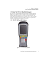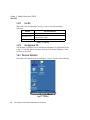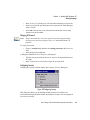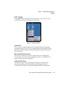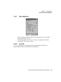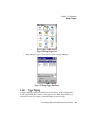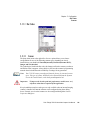
1
7535 G2
Hand-Held Computer
User Manual
October 17, 2007
ISO 9001 Certified
Quality Management System
Part No. 8100075.D
© Copyright 2007 by Psion Teklogix Inc., Mississauga, Ontario
This document and the information it contains is the property of Psion Teklogix Inc.,
is issued in strict confidence, and is not to be reproduced or copied, in whole or in
part, except for the sole purpose of promoting the sale of Teklogix manufactured
goods and services. Furthermore, this document is not to be used as a basis for
design, manufacture, or sub-contract, or in any manner detrimental to the interests of
Psion Teklogix Inc.
Windows® and the Windows Logo are trademarks or registered trademarks of
Microsoft Corporation in the United States and/or other countries.
The Bluetooth word mark and logos are owned by Bluetooth SIG, Inc. and any use of
such marks by Psion Teklogix Inc. is under license.
All trademarks and trade names are the property of their respective holders.
Return-To-Factory Warranty
Psion Teklogix Inc. provides a return to factory warranty on this product for a period
of twelve (12) months in accordance with the Statement of Limited Warranty and
Limitation of Liability provided at www.psionteklogix.com/warranty. (If you are not
already a member of Teknet and you attempt to view this warranty, you will be
asked to register. As a member of Teknet, you will have access to helpful information about your Psion Teklogix products at no charge to you.) In some regions, this
warranty may exceed this period. Please contact your local Psion Teklogix office for
details. For a list of offices, see Appendix A: “Support Services And Worldwide
Offices”. The warranty on Psion Teklogix manufactured equipment does not extend
to any product that has been tampered with, altered, or repaired by any person other
than an employee of an authorized Psion Teklogix service organization. See Psion
Teklogix terms and conditions of sale for full details.
Important:
Psion Teklogix warranties take effect on the date of shipment.
Service
Psion Teklogix provides a complete range of product support services to its customers. For detailed information, please refer to Appendix A: “Support Services And
Worldwide Offices”. This section also provides information about accessing support
services through the Psion Teklogix web site.
Waste Electrical and Electronic Equipment (WEEE) Directive 2002/96/EC
This Product, and its accessories, comply with the requirements of the Waste Electrical and Electronic Equipment (WEEE) Directive 2002/96/EC. If your end-of-life
Psion Teklogix product or accessory carries a label as shown here, please contact
your local country representative for details on how to arrange recycling.
For a list of international subsidiaries, please go to:
www.psionteklogix.com/public.aspx?s=us&p=Contacts.
Restriction On Hazardous Substances (RoHS) Directive 2002/95/EC
What is RoHS?
The European Union has mandated that high environmental standards be met in the
design and manufacture of electronic and electrical products sold in Europe, to
reduce hazardous substances from entering the environment. The “Restriction on
Hazardous Substances Directive (RoHS)” prescribes the maximum trace levels of
lead, cadmium, mercury, hexavalent chromium, and flame retardants PBB and PBDE
that may be contained in a product. Only products meeting these high environmental
standards may be “placed on the market” in EU member states after July 1, 2006.
RoHS Logo
Although there is no legal requirement to mark RoHS-compliant products, Psion
Teklogix Inc. indicates its compliance with the directive as follows:
The RoHS logo located either on the back of the product or underneath the battery in
the battery compartment (or on a related accessory such as the charger or docking
station) signifies that the product is RoHS-compliant as per the EU directive. Other
than as noted below, a Psion Teklogix product that does not have an accompanying
RoHS logo signifies that it was placed on the EU market prior to July 1, 2006, and is
thereby exempt from the directive.
Note:
Not all accessories or peripherals will have a RoHS logo due to physical
space limitations or as a result of their exempt status.
Disclaimer
Every effort has been made to make this material complete, accurate, and up-to-date.
In addition, changes are periodically added to the information herein; these changes
will be incorporated into new editions of the publication.
Psion Teklogix Inc. reserves the right to make improvements and/or changes in the
product(s) and/or the program(s) described in this document without notice, and
shall not be responsible for any damages, including but not limited to consequential
damages, caused by reliance on the material presented, including but not limited to
typographical errors.
TABLE OF CONTENTS
Program License Agreements . .
Approvals And Safety Summary .
. . . . . . . . . . . . . . . . . . . . . . . . xiii
. . . . . . . . . . . . . . . . . . . . . . . . xix
Chapter 1: Introduction
1.1
1.2
1.3
1.4
About This Manual . . . . . . . . . . . . .
Text Conventions . . . . . . . . . . . . . .
7535 G2 Features . . . . . . . . . . . . . .
About The 7535 G2 Hand-Held Computer .
1.4.1 The 7535 G2 Hand-Held Computer .
1.4.2 Regulatory Labels . . . . . . . . . .
.
.
.
.
.
.
.
.
.
.
.
.
.
.
.
.
.
.
.
.
.
.
.
.
.
.
.
.
.
.
.
.
.
.
.
.
.
.
.
.
.
.
.
.
.
.
.
.
.
.
.
.
.
.
.
.
.
.
.
.
.
.
.
.
.
.
.
.
.
.
.
.
.
.
.
.
.
.
.
.
.
.
.
.
.
.
.
.
.
.
3
4
4
7
7
9
Preparing The 7535 G2 For Operation . . . . . . . . . . . . . .
2.1.1 Equipment You Need To Get Started . . . . . . . . . . .
Powering Up The 7535 G2 . . . . . . . . . . . . . . . . . . . .
2.2.1 Charging The Battery . . . . . . . . . . . . . . . . . . .
2.2.2 Installing The Battery And Switching The Hand-Held On
Attaching Carrying Accessories. . . . . . . . . . . . . . . . . .
2.3.1 Attaching The Hand Strap . . . . . . . . . . . . . . . . .
2.3.2 Attaching The Pistol Grip . . . . . . . . . . . . . . . . .
Calibrating The Touchscreen . . . . . . . . . . . . . . . . . . .
Configuring Your Radio. . . . . . . . . . . . . . . . . . . . . .
Configuring An IEEE 802.11 Radio In The Unit . . . . . . . . .
2.6.1 Assigning An IP Address . . . . . . . . . . . . . . . . .
2.6.2 Name Servers Tab . . . . . . . . . . . . . . . . . . . . .
2.6.3 Advanced Features. . . . . . . . . . . . . . . . . . . . .
2.6.3.1 Rearranging Preferred Networks . . . . . . . .
2.6.3.2 Deleting A Preferred Network. . . . . . . . . .
2.6.3.3 Changing Network Properties . . . . . . . . . .
.
.
.
.
.
.
.
.
.
.
.
.
.
.
.
.
.
.
.
.
.
.
.
.
.
.
.
.
.
.
.
.
.
.
.
.
.
.
.
.
.
.
.
.
.
.
.
.
.
.
.
. 13
. 13
. 13
. 13
. 14
. 15
. 15
. 17
. 18
. 18
. 18
. 24
. 25
. 26
. 27
. 27
. 27
Chapter 2: Basic Checkout
2.1
2.2
2.3
2.4
2.5
2.6
Psion Teklogix 7535 G2 Hand-Held Computer User Manual
i
Contents
2.7
Summit Client Utility (SCU) For Model RA2041. .
2.7.1 Assigning The IP Address . . . . . . . . . .
2.7.2 Name Servers Tab . . . . . . . . . . . . . .
2.7.3 Using The SCU To Connect To The WLAN
2.7.3.1 SSID . . . . . . . . . . . . . . . .
2.7.3.2 EAP Type. . . . . . . . . . . . . .
2.7.3.3 Encryption . . . . . . . . . . . . .
2.8 SCU Tabs . . . . . . . . . . . . . . . . . . . . . .
2.8.1 Main Tab . . . . . . . . . . . . . . . . . . .
2.8.2 Config Tab . . . . . . . . . . . . . . . . . .
2.8.2.1 SCU Security Capabilities . . . . .
2.8.2.2 EAP Credentials . . . . . . . . . .
2.8.2.3 ThirdPartyConfig. . . . . . . . . .
2.8.3 Global Settings Tab . . . . . . . . . . . . .
2.8.4 Status Tab . . . . . . . . . . . . . . . . . .
2.8.5 Diags Tab. . . . . . . . . . . . . . . . . . .
2.9 Checking The Scanner . . . . . . . . . . . . . . . .
2.10 Data Transfer Between The 7535 G2 And A PC . .
2.11 Resetting The Hand-Held . . . . . . . . . . . . . .
.
.
.
.
.
.
.
.
.
.
.
.
.
.
.
.
.
.
.
.
.
.
.
.
.
.
.
.
.
.
.
.
.
.
.
.
.
.
.
.
.
.
.
.
.
.
.
.
.
.
.
.
.
.
.
.
.
.
.
.
.
.
.
.
.
.
.
.
.
.
.
.
.
.
.
.
.
.
.
.
.
.
.
.
.
.
.
.
.
.
.
.
.
.
.
.
.
.
.
.
.
.
.
.
.
.
.
.
.
.
.
.
.
.
.
.
.
.
.
.
.
.
.
.
.
.
.
.
.
.
.
.
.
.
.
.
.
.
.
.
.
.
.
.
.
.
.
.
.
.
.
.
.
.
.
.
.
.
.
.
.
.
.
.
.
.
.
.
.
.
.
.
.
.
.
.
.
.
.
.
.
.
.
.
.
.
.
.
.
.
28
28
30
31
32
32
32
34
34
35
37
39
39
40
42
43
44
44
45
.
.
.
.
.
.
.
.
.
.
.
.
.
.
.
.
.
.
.
.
.
.
.
.
.
.
.
.
.
.
.
.
.
.
.
.
.
.
.
.
.
.
.
.
.
.
.
.
.
.
.
.
.
.
.
.
.
.
.
.
.
.
.
.
.
.
.
.
.
.
.
.
.
.
.
.
.
.
.
.
.
.
.
.
.
.
.
.
.
.
.
.
.
.
.
.
.
.
.
.
.
.
.
.
.
.
.
.
.
.
.
.
.
.
.
.
.
.
.
.
.
.
.
.
.
.
.
.
.
.
.
.
.
.
.
.
.
.
.
.
.
.
.
.
.
.
.
.
.
.
.
.
.
.
.
.
.
.
.
.
49
50
50
50
51
52
53
53
53
54
54
55
55
56
57
57
Chapter 3: Getting To Know Your 7535 G2
3.1
3.2
3.3
3.4
ii
Features Of The 7535 G2 . . . . . . . . . . . . . .
The Battery. . . . . . . . . . . . . . . . . . . . . .
3.2.1 Battery Safety . . . . . . . . . . . . . . . .
3.2.2 Removing And Installing The Battery Pack .
3.2.3 Battery Chargers . . . . . . . . . . . . . . .
Switching The Hand-Held On And Off . . . . . . .
The Keyboard . . . . . . . . . . . . . . . . . . . .
3.4.1 Modifier Keys . . . . . . . . . . . . . . . .
3.4.1.1 Activating Modifier Keys . . . . .
3.4.1.2 Locking Modifier Keys. . . . . . .
3.4.2 The Keys . . . . . . . . . . . . . . . . . . .
3.4.3 Function Keys, Softkeys And Macro Keys .
3.4.3.1 Function Keys . . . . . . . . . . .
3.4.3.2 Macro Keys. . . . . . . . . . . . .
3.4.4 Alphanumeric Keyboard: 58-Key . . . . . .
3.4.5 Numeric Keyboard: 36-Key . . . . . . . . .
Psion Teklogix 7535 G2 Hand-Held Computer User Manual
Contents
3.4.6 The Keypad Backlight . . . . . . . . . . . . . . . . . . . . .
The Display . . . . . . . . . . . . . . . . . . . . . . . . . . . . . .
3.5.1 Adjusting The Display Backlight . . . . . . . . . . . . . . .
3.5.2 Adjusting The Contrast . . . . . . . . . . . . . . . . . . . .
3.5.3 Calibrating The Touchscreen . . . . . . . . . . . . . . . . .
3.6 7535 G2 Indicators . . . . . . . . . . . . . . . . . . . . . . . . . .
3.6.1 LEDs . . . . . . . . . . . . . . . . . . . . . . . . . . . . . .
3.6.1.1 Charge LED . . . . . . . . . . . . . . . . . . . . .
3.6.1.2 Radio Traffic LED . . . . . . . . . . . . . . . . . .
3.6.1.3 Scan LED . . . . . . . . . . . . . . . . . . . . . .
3.6.1.4 User Application LED . . . . . . . . . . . . . . . .
3.6.2 Onscreen Indicators . . . . . . . . . . . . . . . . . . . . . .
3.6.3 Audio Indicators . . . . . . . . . . . . . . . . . . . . . . . .
3.6.3.1 Adjusting The Beeper Volume. . . . . . . . . . . .
3.7 Internal Scanners . . . . . . . . . . . . . . . . . . . . . . . . . . .
3.7.1 Scanning Techniques . . . . . . . . . . . . . . . . . . . . .
3.7.2 Scan LED Indicators. . . . . . . . . . . . . . . . . . . . . .
3.7.3 Troubleshooting . . . . . . . . . . . . . . . . . . . . . . . .
3.7.4 Operating One Dimensional (1D) Internal Laser Scanners . .
3.7.5 Operating Internal PDF Laser Scanners . . . . . . . . . . . .
3.7.6 Operating Internal Two Dimensional (2D) Imager Scanners .
3.7.7 Operating RFID/Scanner Modules . . . . . . . . . . . . . .
3.8 Connecting And Disconnecting Tethered Peripherals . . . . . . . .
3.9 Monitoring The Battery And Maximizing Run Time. . . . . . . . .
3.9.1 Storing Batteries . . . . . . . . . . . . . . . . . . . . . . . .
3.10 Monitoring The Network Connection. . . . . . . . . . . . . . . . .
3.11 Uploading Data In A Docking Station . . . . . . . . . . . . . . . .
3.12 General Maintenance . . . . . . . . . . . . . . . . . . . . . . . . .
3.12.1 Caring For The Touchscreen . . . . . . . . . . . . . . . . .
3.12.2 Cleaning The 7535 G2. . . . . . . . . . . . . . . . . . . . .
3.5
.
.
.
.
.
.
.
.
.
.
.
.
.
.
.
.
.
.
.
.
.
.
.
.
.
.
.
.
.
.
. 59
. 60
. 60
. 60
. 60
. 62
. 62
. 63
. 63
. 64
. 64
. 64
. 67
. 67
. 68
. 69
. 69
. 70
. 70
. 71
. 71
. 72
. 72
. 74
. 75
. 75
. 76
. 76
. 76
. 76
.
.
.
.
. 81
. 81
. 81
. 82
Chapter 4: Working With Windows CE
4.1
4.2
Navigating In Windows CE And Applications . . . .
4.1.1 Navigating Using A Touchscreen And Stylus.
4.1.2 Navigating Using The Keyboard . . . . . . .
Working With Files, Folders And Programs . . . . .
.
.
.
.
.
.
.
.
.
.
.
.
.
.
.
.
.
.
.
.
.
.
.
.
.
.
.
.
.
.
.
.
Psion Teklogix 7535 G2 Hand-Held Computer User Manual
iii
Contents
4.3
4.4
4.5
The Startup Desktop . . . . . . . . . . . .
4.3.1 The Desktop Icons . . . . . . . . .
4.3.2 The Taskbar . . . . . . . . . . . .
4.3.2.1 Using The Taskbar . . . .
4.3.2.2 Customizing The Taskbar
The Start Menu. . . . . . . . . . . . . . .
4.4.1 The Desktop . . . . . . . . . . . .
4.4.2 Security Settings . . . . . . . . . .
4.4.3 Programs . . . . . . . . . . . . . .
4.4.4 Shortcuts . . . . . . . . . . . . . .
4.4.5 Settings . . . . . . . . . . . . . . .
4.4.6 Run . . . . . . . . . . . . . . . . .
4.4.7 Shutdown . . . . . . . . . . . . . .
Using A Dialog Box . . . . . . . . . . . .
.
.
.
.
.
.
.
.
.
.
.
.
.
.
.
.
.
.
.
.
.
.
.
.
.
.
.
.
.
.
.
.
.
.
.
.
.
.
.
.
.
.
.
.
.
.
.
.
.
.
.
.
.
.
.
.
.
.
.
.
.
.
.
.
.
.
.
.
.
.
.
.
.
.
.
.
.
.
.
.
.
.
.
.
.
.
.
.
.
.
.
.
.
.
.
.
.
.
.
.
.
.
.
.
.
.
.
.
.
.
.
.
.
.
.
.
.
.
.
.
.
.
.
.
.
.
.
.
.
.
.
.
.
.
.
.
.
.
.
.
.
.
.
.
.
.
.
.
.
.
.
.
.
.
.
.
.
.
.
.
.
.
.
.
.
.
.
.
.
.
.
.
.
.
.
.
.
.
.
.
.
.
.
.
.
.
.
.
.
.
.
.
.
.
.
.
.
.
.
.
.
.
.
.
.
.
.
.
.
.
83
84
85
85
86
87
88
88
90
91
93
94
94
95
Remote Connect . . . . . . . . . . . . . . .
The TekTerm Application . . . . . . . . . .
Pocket PC Compatibility. . . . . . . . . . .
The Control Panel . . . . . . . . . . . . . .
Control Panel Icons . . . . . . . . . . . . .
Basic Setup. . . . . . . . . . . . . . . . . .
5.6.1 Display Properties . . . . . . . . . .
5.6.1.1 Display Contrast . . . . . .
5.6.1.2 Display Backlight . . . . .
5.6.1.3 Display Appearance . . . .
5.6.2 Keyboard Properties . . . . . . . . .
5.6.2.1 Key Repeat . . . . . . . . .
5.6.2.2 Keyboard Backlight . . . .
5.6.2.3 Keyboard One Shot Modes.
5.6.2.4 Keyboard Macro Keys . . .
5.6.2.5 Unicode Mapping . . . . .
5.6.2.6 Scancode Remapping . . .
5.6.3 Volume And Sound Properties . . . .
5.6.3.1 Volume Adjustments . . . .
5.6.3.2 Sound Tab . . . . . . . . .
5.6.4 Power Management Properties. . . .
5.6.4.1 Battery Capacity . . . . . .
.
.
.
.
.
.
.
.
.
.
.
.
.
.
.
.
.
.
.
.
.
.
.
.
.
.
.
.
.
.
.
.
.
.
.
.
.
.
.
.
.
.
.
.
.
.
.
.
.
.
.
.
.
.
.
.
.
.
.
.
.
.
.
.
.
.
.
.
.
.
.
.
.
.
.
.
.
.
.
.
.
.
.
.
.
.
.
.
.
.
.
.
.
.
.
.
.
.
.
.
.
.
.
.
.
.
.
.
.
.
.
.
.
.
.
.
.
.
.
.
.
.
.
.
.
.
.
.
.
.
.
.
.
.
.
.
.
.
.
.
.
.
.
.
.
.
.
.
.
.
.
.
.
.
.
.
.
.
.
.
.
.
.
.
.
.
.
.
.
.
.
.
.
.
.
.
.
.
.
.
.
.
.
.
.
.
.
.
.
.
.
.
.
.
.
.
.
.
.
.
.
.
.
.
.
.
.
.
.
.
.
.
.
.
.
.
.
.
.
.
.
.
.
.
.
.
.
.
.
.
.
.
.
.
.
.
.
.
.
.
.
.
.
.
.
.
.
.
.
.
.
.
.
.
.
.
.
.
.
.
.
.
.
.
.
.
.
.
.
.
.
.
.
.
.
.
.
.
.
.
.
.
.
.
.
.
. 103
. 103
. 103
. 103
. 105
. 109
. 109
. 110
. 110
. 112
. 113
. 113
. 114
. 115
. 116
. 118
. 120
. 122
. 123
. 123
. 124
. 124
Chapter 5: Configuration
5.1
5.2
5.3
5.4
5.5
5.6
iv
Psion Teklogix 7535 G2 Hand-Held Computer User Manual
Contents
5.6.4.2 Power Saving Schemes . . . . . . . .
5.6.4.3 Suspend Threshold. . . . . . . . . . .
5.6.4.4 Calibrate . . . . . . . . . . . . . . . .
5.6.4.5 Advanced . . . . . . . . . . . . . . .
5.6.4.6 Devices. . . . . . . . . . . . . . . . .
5.6.5 Stylus Properties . . . . . . . . . . . . . . . . .
5.6.5.1 Double-Tap . . . . . . . . . . . . . .
5.6.5.2 Calibration . . . . . . . . . . . . . . .
5.6.5.3 Touch . . . . . . . . . . . . . . . . .
5.6.6 Manage Triggers. . . . . . . . . . . . . . . . .
5.6.6.1 Trigger Mappings . . . . . . . . . . .
5.6.6.2 Add And Edit Trigger Mapping . . . .
5.6.7 Certificate Assignment . . . . . . . . . . . . .
5.7 Bluetooth Setup . . . . . . . . . . . . . . . . . . . . .
5.7.1 The Devices Tab . . . . . . . . . . . . . . . . .
5.7.2 The Servers Tab . . . . . . . . . . . . . . . . .
5.7.3 Outgoing Tab . . . . . . . . . . . . . . . . . .
5.7.4 Active Conn. Tab . . . . . . . . . . . . . . . .
5.7.5 The Properties Tab. . . . . . . . . . . . . . . .
5.7.6 The Bluetooth GPRS WAN Connection . . . .
5.8 Total Recall . . . . . . . . . . . . . . . . . . . . . . .
5.8.1 Creating A Backup Profile. . . . . . . . . . . .
5.8.2 Restoring A Profile . . . . . . . . . . . . . . .
5.9 The Storage Manager . . . . . . . . . . . . . . . . . .
5.9.1 Formatting A Memory Card . . . . . . . . . . .
5.9.2 Creating Partitions . . . . . . . . . . . . . . . .
5.9.3 Partition Management . . . . . . . . . . . . . .
5.10 IPv6 Support. . . . . . . . . . . . . . . . . . . . . . .
5.11 Scanner Settings . . . . . . . . . . . . . . . . . . . . .
5.11.1 Bar Codes . . . . . . . . . . . . . . . . . . . .
5.11.1.1 Scanner. . . . . . . . . . . . . . . . .
5.11.2 Decoded (Internal) Scanners. . . . . . . . . . .
5.11.2.1 Options. . . . . . . . . . . . . . . . .
5.11.2.2 Advanced Options . . . . . . . . . . .
5.11.2.3 2D Scanning Options (Model SE2223)
5.11.2.4 Data Options . . . . . . . . . . . . . .
5.11.2.5 Code 39 . . . . . . . . . . . . . . . .
5.11.2.6 Code 128. . . . . . . . . . . . . . . .
.
.
.
.
.
.
.
.
.
.
.
.
.
.
.
.
.
.
.
.
.
.
.
.
.
.
.
.
.
.
.
.
.
.
.
.
.
.
.
.
.
.
.
.
.
.
.
.
.
.
.
.
.
.
.
.
.
.
.
.
.
.
.
.
.
.
.
.
.
.
.
.
.
.
.
.
.
.
.
.
.
.
.
.
.
.
.
.
.
.
.
.
.
.
.
.
.
.
.
.
.
.
.
.
.
.
.
.
.
.
.
.
.
.
.
.
.
.
.
.
.
.
.
.
.
.
.
.
.
.
.
.
.
.
.
.
.
.
.
.
.
.
.
.
.
.
.
.
.
.
.
.
.
.
.
.
.
.
.
.
.
.
.
.
.
.
.
.
.
.
.
.
.
.
.
.
.
.
.
.
.
.
.
.
.
.
.
.
.
.
.
.
.
.
.
.
.
.
.
.
.
.
.
.
.
.
.
.
.
.
.
.
.
.
.
.
.
.
.
.
.
.
.
.
.
.
.
.
.
.
.
.
.
.
.
.
.
.
.
.
.
.
.
.
.
.
.
.
.
.
.
.
.
.
.
.
.
.
.
.
.
.
.
.
.
.
.
.
.
.
.
.
.
.
.
.
.
.
.
.
.
.
.
.
.
.
.
.
.
.
.
.
.
.
.
.
.
.
.
.
.
.
.
.
125
126
127
127
128
129
129
130
130
130
131
133
135
136
137
140
141
142
143
143
150
151
156
156
156
157
158
161
162
163
163
164
164
165
167
167
168
171
Psion Teklogix 7535 G2 Hand-Held Computer User Manual
v
Contents
5.11.2.7 EAN 13 . . . . . . . . . . . . . . . . . .
5.11.2.8 EAN 8 . . . . . . . . . . . . . . . . . .
5.11.2.9 UPC A . . . . . . . . . . . . . . . . . .
5.11.2.10 UPC E . . . . . . . . . . . . . . . . . .
5.11.2.11 UPC/EAN Shared Settings . . . . . . . .
5.11.2.12 Code 93. . . . . . . . . . . . . . . . . .
5.11.2.13 Codabar. . . . . . . . . . . . . . . . . .
5.11.2.14 MSI Plessey . . . . . . . . . . . . . . .
5.11.2.15 Interleaved 2 of 5 . . . . . . . . . . . . .
5.11.2.16 Discrete 2 of 5 . . . . . . . . . . . . . .
5.11.2.17 RSS Code (Reduced Space Symbology).
5.11.2.18 Composite (Model SE2223) . . . . . . .
5.11.2.19 PDF-417 (Model SE2223) . . . . . . . .
5.11.2.20 Micro PDF-417 (Model SE2223) . . . .
5.11.3 Decoded (Intermec ISCP) . . . . . . . . . . . . .
5.11.3.1 Options . . . . . . . . . . . . . . . . . .
5.11.3.2 Advanced Options . . . . . . . . . . . .
5.11.3.3 Code 39. . . . . . . . . . . . . . . . . .
5.11.3.4 Code 128 . . . . . . . . . . . . . . . . .
5.11.3.5 EAN 13 . . . . . . . . . . . . . . . . . .
5.11.3.6 EAN 8 . . . . . . . . . . . . . . . . . .
5.11.3.7 UPC A . . . . . . . . . . . . . . . . . .
5.11.3.8 UPC E . . . . . . . . . . . . . . . . . .
5.11.3.9 UPC/EAN Shared Settings . . . . . . . .
5.11.3.10 Code 93. . . . . . . . . . . . . . . . . .
5.11.3.11 Codabar. . . . . . . . . . . . . . . . . .
5.11.3.12 MSI Plessey . . . . . . . . . . . . . . .
5.11.3.13 Code 11 . . . . . . . . . . . . . . . . . .
5.11.3.14 Interleaved 2 of 5 . . . . . . . . . . . . .
5.11.3.15 Matrix 2 of 5 . . . . . . . . . . . . . . .
5.11.3.16 Discrete 2 of 5 . . . . . . . . . . . . . .
5.11.3.17 Telepen . . . . . . . . . . . . . . . . . .
5.11.3.18 RSS Code (Reduced Space Symbology).
5.11.3.19 PDF-417 . . . . . . . . . . . . . . . . .
5.11.3.20 Micro PDF-417. . . . . . . . . . . . . .
5.11.3.21 Codablock . . . . . . . . . . . . . . . .
5.11.4 Imager . . . . . . . . . . . . . . . . . . . . . . .
5.11.4.1 Options . . . . . . . . . . . . . . . . . .
5.11.4.2 Advanced Options . . . . . . . . . . . .
5.11.4.3 Code 39. . . . . . . . . . . . . . . . . .
5.11.4.4 Code 128 . . . . . . . . . . . . . . . . .
vi
Psion Teklogix 7535 G2 Hand-Held Computer User Manual
.
.
.
.
.
.
.
.
.
.
.
.
.
.
.
.
.
.
.
.
.
.
.
.
.
.
.
.
.
.
.
.
.
.
.
.
.
.
.
.
.
.
.
.
.
.
.
.
.
.
.
.
.
.
.
.
.
.
.
.
.
.
.
.
.
.
.
.
.
.
.
.
.
.
.
.
.
.
.
.
.
.
.
.
.
.
.
.
.
.
.
.
.
.
.
.
.
.
.
.
.
.
.
.
.
.
.
.
.
.
.
.
.
.
.
.
.
.
.
.
.
.
.
.
.
.
.
.
.
.
.
.
.
.
.
.
.
.
.
.
.
.
.
.
.
.
.
.
.
.
.
.
.
.
.
.
.
.
.
.
.
.
.
.
.
.
.
.
.
.
.
.
.
.
.
.
.
.
.
.
.
.
.
.
.
.
.
.
.
.
.
.
.
.
.
.
.
.
.
.
.
.
.
.
.
.
.
.
.
.
.
.
.
.
.
.
.
.
.
.
.
.
.
.
.
.
.
.
.
.
.
.
.
.
.
.
.
.
.
.
.
.
.
.
.
.
. 172
. 173
. 173
. 174
. 175
. 176
. 176
. 177
. 178
. 179
. 180
. 180
. 181
. 181
. 182
. 182
. 182
. 183
. 185
. 186
. 187
. 187
. 188
. 188
. 189
. 189
. 191
. 191
. 192
. 193
. 193
. 194
. 194
. 195
. 195
. 196
. 196
. 197
. 198
. 200
. 201
Contents
5.11.4.5 EAN 13 . . . . .
5.11.4.6 EAN 8 . . . . . .
5.11.4.7 UPC A . . . . . .
5.11.4.8 UPC E . . . . . .
5.11.4.9 Code 93 . . . . .
5.11.4.10 Codabar . . . . .
5.11.4.11 Interleaved 2 of 5
5.11.4.12 RSS Code . . . .
5.11.4.13 Composite . . . .
5.11.4.14 PDF-417 . . . . .
5.11.4.15 Micro PDF-417 .
5.11.4.16 2D Data Matrix .
5.11.4.17 2D QR Code . . .
5.11.4.18 2D Maxicode . .
5.11.4.19 2D Aztec . . . . .
5.11.4.20 Postal: PlaNET. .
5.11.4.21 Postal: PostNET .
5.11.4.22 Postal: Australian
5.11.4.23 Postal: Japanese .
5.11.4.24 Postal: Korean . .
5.11.4.25 Postal: Royal. . .
5.11.4.26 Postal: Kix . . . .
5.11.4.27 Postal: Canadian .
5.11.5 Non-Decoded Scanners . .
5.11.5.1 Options. . . . . .
5.11.5.2 Code 39 . . . . .
5.11.5.3 Code 128. . . . .
5.11.5.4 EAN 13 . . . . .
5.11.5.5 EAN 8 . . . . . .
5.11.5.6 UPC A . . . . . .
5.11.5.7 UPC E . . . . . .
5.11.5.8 Codabar . . . . .
5.11.5.9 Code 93 . . . . .
5.11.5.10 Code 11 . . . . .
5.11.5.11 Interleaved 2 of 5
5.11.5.12 MSI Plessey . . .
5.11.5.13 Discrete 2 of 5 . .
5.11.5.14 IATA 2 of 5 . . .
5.11.6 Options. . . . . . . . . . .
5.11.6.1 Double Click. . .
5.11.6.2 Display. . . . . .
.
.
.
.
.
.
.
.
.
.
.
.
.
.
.
.
.
.
.
.
.
.
.
.
.
.
.
.
.
.
.
.
.
.
.
.
.
.
.
.
.
.
.
.
.
.
.
.
.
.
.
.
.
.
.
.
.
.
.
.
.
.
.
.
.
.
.
.
.
.
.
.
.
.
.
.
.
.
.
.
.
.
.
.
.
.
.
.
.
.
.
.
.
.
.
.
.
.
.
.
.
.
.
.
.
.
.
.
.
.
.
.
.
.
.
.
.
.
.
.
.
.
.
.
.
.
.
.
.
.
.
.
.
.
.
.
.
.
.
.
.
.
.
.
.
.
.
.
.
.
.
.
.
.
.
.
.
.
.
.
.
.
.
.
.
.
.
.
.
.
.
.
.
.
.
.
.
.
.
.
.
.
.
.
.
.
.
.
.
.
.
.
.
.
.
.
.
.
.
.
.
.
.
.
.
.
.
.
.
.
.
.
.
.
.
.
.
.
.
.
.
.
.
.
.
.
.
.
.
.
.
.
.
.
.
.
.
.
.
.
.
.
.
.
.
.
.
.
.
.
.
.
.
.
.
.
.
.
.
.
.
.
.
.
.
.
.
.
.
.
.
.
.
.
.
.
.
.
.
.
.
.
.
.
.
.
.
.
.
.
.
.
.
.
.
.
.
.
.
.
.
.
.
.
.
.
.
.
.
.
.
.
.
.
.
.
.
.
.
.
.
.
.
.
.
.
.
.
.
.
.
.
.
.
.
.
.
.
.
.
.
.
.
.
.
.
.
.
.
.
.
.
.
.
.
.
.
.
.
.
.
.
.
.
.
.
.
.
.
.
.
.
.
.
.
.
.
.
.
.
.
.
.
.
.
.
.
.
.
.
.
.
.
.
.
.
.
.
.
.
.
.
.
.
.
.
.
.
.
.
.
.
.
.
.
.
.
.
.
.
.
.
.
.
.
.
.
.
.
.
.
.
.
.
.
.
.
.
.
.
.
.
.
.
.
.
.
.
.
.
.
.
.
.
.
.
.
.
.
.
.
.
.
.
.
.
.
.
.
.
.
.
.
.
.
.
.
.
.
.
.
.
.
.
.
.
.
.
.
.
.
.
.
.
.
.
.
.
.
.
.
.
.
.
.
.
.
.
.
.
.
.
.
.
.
.
.
.
.
.
.
.
.
.
.
.
.
.
.
.
.
.
.
.
.
.
.
.
.
.
.
.
.
.
.
.
.
.
.
.
.
.
.
.
.
.
.
.
.
.
.
.
.
.
.
.
.
.
.
.
.
.
.
.
.
.
.
.
.
.
.
.
.
.
.
.
.
.
.
.
.
.
.
.
.
.
.
.
.
.
.
.
.
.
.
.
.
.
.
.
.
.
.
.
.
.
.
.
.
.
.
.
.
.
.
.
.
.
.
.
.
.
.
.
.
.
.
.
.
.
.
.
.
.
.
.
.
.
.
.
.
.
.
.
.
.
.
.
.
.
.
.
.
.
.
.
.
.
.
.
.
.
.
.
.
.
.
.
.
.
.
.
.
.
.
.
.
.
.
.
.
.
.
.
.
.
.
.
.
.
.
.
.
.
.
.
.
.
.
.
.
.
.
.
.
.
.
.
.
.
.
.
.
.
.
.
.
.
.
.
.
.
.
.
.
.
.
.
.
.
.
.
.
.
.
.
.
.
.
.
.
.
.
.
.
.
.
.
.
.
.
.
.
.
.
.
.
.
.
.
.
.
.
.
.
.
.
.
.
201
202
202
202
203
203
203
203
204
204
204
204
205
205
206
206
206
206
206
207
207
207
207
208
209
209
211
212
213
213
214
215
215
216
217
217
218
218
219
220
220
Psion Teklogix 7535 G2 Hand-Held Computer User Manual
vii
Contents
5.11.7 Translations. . . . . . . . . . . . . . . . . . . .
5.11.8 Ports . . . . . . . . . . . . . . . . . . . . . . .
5.11.8.1 Tether Port (COM1) . . . . . . . . . .
5.11.8.2 Console Port (COM3) . . . . . . . . .
5.11.8.3 Port Replicator Tether (COM6) . . . .
5.11.8.4 Port Replicator 9-pin (COM5) . . . . .
5.12 SNMP (Simple Network Management Protocol) Setup.
5.12.1 Contact Tab. . . . . . . . . . . . . . . . . . . .
5.12.2 Communities Tab. . . . . . . . . . . . . . . . .
5.12.2.1 Adding A Community . . . . . . . . .
5.12.2.2 Modifying A Community Setting . . .
5.12.2.3 Removing An Existing Community . .
5.12.3 Trap Destination Tab . . . . . . . . . . . . . . .
5.12.3.1 Enabling Authentication TRAPS. . . .
5.12.3.2 Adding A Destination . . . . . . . . .
5.12.3.3 Changing A Destination . . . . . . . .
5.12.3.4 Removing A Trap Destination . . . . .
5.12.4 Permitted Hosts Tab . . . . . . . . . . . . . . .
5.12.4.1 Adding A Host . . . . . . . . . . . . .
5.12.4.2 Changing A Host . . . . . . . . . . . .
.
.
.
.
.
.
.
.
.
.
.
.
.
.
.
.
.
.
.
.
.
.
.
.
.
.
.
.
.
.
.
.
.
.
.
.
.
.
.
.
.
.
.
.
.
.
.
.
.
.
.
.
.
.
.
.
.
.
.
.
.
.
.
.
.
.
.
.
.
.
.
.
.
.
.
.
.
.
.
.
.
.
.
.
.
.
.
.
.
.
.
.
.
.
.
.
.
.
.
.
.
.
.
.
.
.
.
.
.
.
.
.
.
.
.
.
.
.
.
.
.
.
.
.
.
.
.
.
.
.
.
.
.
.
.
.
.
.
.
.
. 221
. 223
. 223
. 225
. 226
. 227
. 228
. 229
. 230
. 230
. 231
. 231
. 232
. 232
. 232
. 233
. 233
. 234
. 234
. 235
External Bar Code Readers . . . . . . . . . . . . . . . . . . . .
6.1.1 PowerScan® Standard, LR and XLR Bar Code Scanners .
6.1.2 Entering Data With The Bar Code Reader . . . . . . . . .
RD7950 Integrated UHF RFID Reader . . . . . . . . . . . . . .
Batteries . . . . . . . . . . . . . . . . . . . . . . . . . . . . . .
Battery Charging . . . . . . . . . . . . . . . . . . . . . . . . . .
6.4.1 Battery Gas Gauge Calibration. . . . . . . . . . . . . . .
Gang Charger . . . . . . . . . . . . . . . . . . . . . . . . . . .
6.5.1 Installation . . . . . . . . . . . . . . . . . . . . . . . . .
6.5.2 Operator Controls . . . . . . . . . . . . . . . . . . . . .
6.5.3 Charge Indicators. . . . . . . . . . . . . . . . . . . . . .
6.5.4 Charging Batteries . . . . . . . . . . . . . . . . . . . . .
6.5.5 Troubleshooting . . . . . . . . . . . . . . . . . . . . . .
6.5.5.1 Excessive Charge Duration. . . . . . . . . . . .
6.5.5.2 Improper Battery Storage. . . . . . . . . . . . .
6.5.5.3 Indicator Flashing Red . . . . . . . . . . . . . .
.
.
.
.
.
.
.
.
.
.
.
.
.
.
.
.
.
.
.
.
.
.
.
.
.
.
.
.
.
.
.
.
. 239
. 239
. 239
. 239
. 240
. 240
. 240
. 241
. 241
. 242
. 242
. 243
. 243
. 243
. 243
. 244
Chapter 6: Peripheral Devices & Accessories
6.1
6.2
6.3
6.4
6.5
viii
Psion Teklogix 7535 G2 Hand-Held Computer User Manual
Contents
6.5.5.4 Power LED Does Not Light Up . . . . . . . . . .
6.5.5.5 Indicator Does Not Light When Battery Installed.
6.6 Combo Charger . . . . . . . . . . . . . . . . . . . . . . . . . . .
6.6.1 Installation . . . . . . . . . . . . . . . . . . . . . . . . . .
6.6.2 Operator Controls . . . . . . . . . . . . . . . . . . . . . .
6.6.3 Using the Combo Charger With The 7535 G2 . . . . . . .
6.6.4 Charging The Spare Battery . . . . . . . . . . . . . . . . .
6.6.5 Charge Indicators . . . . . . . . . . . . . . . . . . . . . .
6.6.6 Troubleshooting . . . . . . . . . . . . . . . . . . . . . . .
6.7 Combo Dock . . . . . . . . . . . . . . . . . . . . . . . . . . . .
6.7.1 Installation . . . . . . . . . . . . . . . . . . . . . . . . . .
6.7.2 Using The Combo Dock . . . . . . . . . . . . . . . . . . .
6.7.3 Network Access . . . . . . . . . . . . . . . . . . . . . . .
6.7.4 Troubleshooting . . . . . . . . . . . . . . . . . . . . . . .
6.8 Quad Dock . . . . . . . . . . . . . . . . . . . . . . . . . . . . .
6.8.1 Installation . . . . . . . . . . . . . . . . . . . . . . . . . .
6.8.2 Indicators And Controls . . . . . . . . . . . . . . . . . . .
6.8.3 Using The Quad Dock . . . . . . . . . . . . . . . . . . . .
6.8.4 Network Access . . . . . . . . . . . . . . . . . . . . . . .
6.8.4.1 Network Addressing . . . . . . . . . . . . . . . .
6.8.5 Battery Charging. . . . . . . . . . . . . . . . . . . . . . .
6.8.6 Troubleshooting . . . . . . . . . . . . . . . . . . . . . . .
6.8.6.1 Network Link Unsuccessful . . . . . . . . . . . .
6.8.6.2 7535 G2 LED Does Not Light When Docked. . .
6.9 Portable Docking Module (PDM). . . . . . . . . . . . . . . . . .
6.10 Bluetooth Peripherals . . . . . . . . . . . . . . . . . . . . . . . .
6.11 The 7535 G2 Picker Cradle . . . . . . . . . . . . . . . . . . . . .
6.11.1 Picker Cradle Mounting Recommendations. . . . . . . . .
6.11.1.1 Mounting Template . . . . . . . . . . . . . . . .
6.11.2 Wiring Guidelines . . . . . . . . . . . . . . . . . . . . . .
6.11.3 Using The Picker Cradle. . . . . . . . . . . . . . . . . . .
6.11.4 Maintaining The Picker Cradle . . . . . . . . . . . . . . .
6.11.5 Powered Cradle Installation In High Voltage Vehicles . . .
6.11.5.1 Extreme Wet Environments . . . . . . . . . . . .
6.11.6 Powered Cradle Installation . . . . . . . . . . . . . . . . .
6.11.6.1 Wiring Vehicle Power To The Cradle . . . . . . .
6.11.7 The Port Replicator . . . . . . . . . . . . . . . . . . . . .
.
.
.
.
.
.
.
.
.
.
.
.
.
.
.
.
.
.
.
.
.
.
.
.
.
.
.
.
.
.
.
.
.
.
.
.
.
.
.
.
.
.
.
.
.
.
.
.
.
.
.
.
.
.
.
.
.
.
.
.
.
.
.
.
.
.
.
.
.
.
.
.
.
.
244
244
244
245
245
245
245
246
246
247
247
247
247
247
248
248
248
249
249
249
249
249
250
250
250
253
253
254
254
255
255
255
256
256
257
258
258
Psion Teklogix 7535 G2 Hand-Held Computer User Manual
ix
Contents
6.12 Tether Adaptor Cables . . . . . . . . . . . . . . . . . . . . . . . . . . 259
Chapter 7: Specifications
7.1
7.2
7.3
7.4
7.5
7.6
7.7
7.8
7.9
7535 G2 Hand-Held Computer Specifications . . . . . . . . . . . . . 263
Radio Specifications . . . . . . . . . . . . . . . . . . . . . . . . . . . 265
Internal Scanner Port. . . . . . . . . . . . . . . . . . . . . . . . . . . 266
RFID Applications . . . . . . . . . . . . . . . . . . . . . . . . . . . . 267
External Scanners . . . . . . . . . . . . . . . . . . . . . . . . . . . . 267
Internal Scanner Specifications . . . . . . . . . . . . . . . . . . . . . 267
7.6.1 EV15 Scanner Specifications . . . . . . . . . . . . . . . . . . 268
7.6.1.1 EV15 Decode Zones . . . . . . . . . . . . . . . . . . 269
7.6.2 SE1200 High Performance & Long Range Specifications. . . . 270
7.6.3 SE1200 Advanced Long Range & SE2223PDF Specifications . 271
7.6.3.1 SE1200 And SE2223 Decode Zones. . . . . . . . . . 272
7.6.4 SE1224HP Specifications . . . . . . . . . . . . . . . . . . . . 273
7.6.4.1 SE1224HP Decode Zones . . . . . . . . . . . . . . . 274
7.6.5 SE1524ER – Extended Range Scanner . . . . . . . . . . . . . 275
7.6.5.1 SE1524ER Decode Zones . . . . . . . . . . . . . . . 276
7.6.6 SX5400 Imager. . . . . . . . . . . . . . . . . . . . . . . . . . 277
7.6.6.1 Near, Far & Depth Of Reading – SX5400* . . . . . . 278
External Scanner Specifications . . . . . . . . . . . . . . . . . . . . . 279
7.7.1 PowerScan® LR and XLR Industrial Scanner Specs . . . . . . 279
7.7.2 PowerScan® Standard Range Scanner Specs . . . . . . . . . . 281
RD7950 Integrated UHF RFID Reader . . . . . . . . . . . . . . . . . 282
HU3000 - 1900 mAh Lithium-Ion Battery Pack . . . . . . . . . . . . 283
Appendices
Appendix A: Support Services And Worldwide Offices
A.1 Technical Support . . . . . . . . . . . . . . . . . . . . . . . . . . . .A-1
A.2 Product Repairs . . . . . . . . . . . . . . . . . . . . . . . . . . . . .A-1
A.3 Worldwide Offices . . . . . . . . . . . . . . . . . . . . . . . . . . . .A-2
Appendix B: Port Pinouts
B.1 Tether Port Pinout . . . . . . . . . . . . . . . . . . . . . . . . . . . . B-3
B.2 Docking Station Connector . . . . . . . . . . . . . . . . . . . . . . . B-3
x
Psion Teklogix 7535 G2 Hand-Held Computer User Manual
Contents
B.3 Battery Contacts . . . . . . . . . . . . . . . . . . . . . . . . . . . . . B-4
B.4 JB5 To USB Type B Cable - P/N CA1020 . . . . . . . . . . . . . . . B-5
B.5 JB5 To RS-232 Serial Cable - P/N CA1010 . . . . . . . . . . . . . . B-5
Appendix C: Connecting To Windows PCs
C.1
C.2
C.3
C.4
Overview . . . . . . . . . . . . . . . . . .
Installing Microsoft ActiveSync . . . . . .
Installing Windows Mobile Device Center .
USB Setup Application . . . . . . . . . . .
C.4.1 Launching The Application . . . . .
C.4.2 Installation Complete Dialog Box .
.
.
.
.
.
.
.
.
.
.
.
.
.
.
.
.
.
.
.
.
.
.
.
.
.
.
.
.
.
.
.
.
.
.
.
.
.
.
.
.
.
.
.
.
.
.
.
.
.
.
.
.
.
.
.
.
.
.
.
.
.
.
.
.
.
.
.
.
.
.
.
.
.
.
.
.
.
.
.
.
.
.
.
.
C-3
C-3
C-3
C-4
C-5
C-7
.
.
.
.
.
.
.
.
.
.
.
.
.
.
.
.
.
.
.
.
.
.
.
.
.
.
.
.
.
.
.
.
.
.
.
.
.
.
.
.
.
.
.
.
.
.
.
.
.
.
.
.
.
.
.
.
. D-3
. D-3
. D-4
. D-6
. D-8
D-15
D-17
Appendix D: Wireless Wide Area Network (WWAN)
D.1 Wireless WAN. . . . . . . . . . .
D.1.1 Taskbar Icons . . . . . . .
D.1.2 Establishing A Connection
D.1.3 Advanced Information . .
D.1.4 Tools Menu . . . . . . . .
D.1.5 SMS Menu . . . . . . . .
D.2 Power Mode . . . . . . . . . . . .
.
.
.
.
.
.
.
.
.
.
.
.
.
.
.
.
.
.
.
.
.
.
.
.
.
.
.
.
.
.
.
.
.
.
.
.
.
.
.
.
.
.
.
.
.
.
.
.
.
.
.
.
.
.
.
.
.
.
.
.
.
.
.
.
.
.
.
.
.
.
Index . . . . . . . . . . . . . . . . . . . . . . . . . . . . . . . . . . . . . . . .I
Psion Teklogix 7535 G2 Hand-Held Computer User Manual
xi
PROGRAM LICENSE AGREEMENTS
Microsoft's End User License Agreement
You have acquired a device (“DEVICE”) that includes software licensed by Psion
Teklogix Inc. from Microsoft Licensing Inc. or its affiliates (‘MS”). Those installed
software products of MS origin, as well as associated media, printed materials, and
“online” or electronic documentation (“SOFTWARE”) are protected by international intellectual property laws and treaties. The SOFTWARE is licensed, not sold.
All rights reserved.
IF YOU DO NOT AGREE TO THIS END USER LICENSE AGREEMENT
(“EULA”), DO NOT USE THE DEVICE OR COPY THE SOFTWARE.
INSTEAD, PROMPTLY CONTACT PSION TEKLOGIX INC. FOR INSTRUCTIONS ON RETURN OF THE UNUSED DEVICE(S) FOR A REFUND. ANY
USE OF THE SOFTWARE, INCLUDING BUT NOT LIMITED TO USE ON
THE DEVICE, WILL CONSTITUTE YOUR AGREEMENT TO THIS
EULA (OR RATIFICATION OF ANY PREVIOUS CONSENT).
GRANT OF SOFTWARE LICENSE. This EULA grants you the following
license:
•
•
•
You may use the SOFTWARE only on the DEVICE.
NOT FAULT TOLERANT. THE SOFTWARE IS NOT FAULT TOLERANT. PSION TEKLOGIX INC. HAS INDEPENDENTLY DETERMINED
HOW TO USE THE SOFTWARE IN THE DEVICE, AND MS HAS
RELIED UPON PSION TEKLOGIX INC. TO CONDUCT SUFFICIENT
TESTING TO DETERMINE THAT THE SOFTWARE IS SUITABLE FOR
SUCH USE.
NO WARRANTIES FOR THE SOFTWARE. THE SOFTWARE is provided “AS IS” and with all faults. THE ENTIRE RISK AS TO SATISFACTORY QUALITY, PERFORMANCE, ACCURACY, AND EFFORT
(INCLUDING LACK OF NEGLIGENCE) IS WITH YOU. ALSO,
THERE IS NO WARRANTY AGAINST INTERFERENCE WITH
YOUR ENJOYMENT OF THE SOFTWARE OR AGAINST
Psion Teklogix 7535 G2 Hand-Held Computer User Manual
xiii
License Agreement
•
•
•
•
•
xiv
INFRINGEMENT. IF YOU HAVE RECEIVED ANY WARRANTIES
REGARDING THE DEVICE OR THE SOFTWARE, THOSE WARRANTIES DO NOT ORIGINATE FROM, AND ARE NOT BINDING ON, MS.
Note on Java Support. The SOFTWARE may contain support for programs
written in Java. Java technology is not fault tolerant and is not designed, manufactured, or intended for use or resale as online control equipment in hazardous
environments requiring fail-safe performance, such as in the operation of
nuclear facilities, aircraft navigation or communication systems, air traffic control, direct life support machines, or weapons systems, in which the failure of
Java technology could lead directly to death, personal injury, or severe physical or environmental damage. Sun Microsystems, Inc. has contractually obligated MS to make this disclaimer.
No Liability for Certain Damages. EXCEPT AS PROHIBITED BY LAW,
MS SHALL HAVE NO LIABILITY FOR ANY INDIRECT, SPECIAL,
CONSEQUENTIAL OR INCIDENTAL DAMAGES ARISING FROM
OR IN CONNECTION WITH THE USE OR PERFORMANCE OF
THE SOFTWARE. THIS LIMITATION SHALL APPLY EVEN IF ANY
REMEDY FAILS OF ITS ESSENTIAL PURPOSE. IN NO EVENT
SHALL MS BE LIABLE FOR ANY AMOUNT IN EXCESS OF U.S.
TWO HUNDRED FIFTY DOLLARS (U.S.$250.OO).
Limitations on Reverse Engineering, Decompilation, and Disassembly.
You may not reverse engineer, decompile, or disassemble the SOFTWARE,
except and only to the extent that such activity is expressly permitted by applicable law notwithstanding this limitation.
SOFTWARE TRANSFER ALLOWED BUT WITH RESTRICTIONS.
You may permanently transfer rights under this EULA only as part of a permanent sale or transfer of the Device, and only if the recipient agrees to this
EULA. If the SOFTWARE is an upgrade, any transfer must also include all
prior versions of the SOFTWARE.
EXPORT RESTRICTIONS. You acknowledge that SOFTWARE is subject
to U.S. export jurisdiction. You agree to comply with all applicable international and national laws that apply to the SOFTWARE, including the U.S.
Export Administration Regulations, as well as end-user, end-use and destination restrictions issued by U.S. and other governments. For additional information see http://www.microsoft.com/exporting/.
Psion Teklogix 7535 G2 Hand-Held Computer User Manual
License Agreement
Psion Teklogix Inc. End User License Agreement
IMPORTANT – READ CAREFULLY:
This License Agreement (“Agreement”) is a legal agreement between you and Psion
Teklogix (“we”), the licensor of this software package (“Software”), for your use of
the Software only as authorized in this Agreement.
By clicking on the “Accept” or other appropriate assent button and/or installing the
Software, you agree to be and are hereby bound by the terms and conditions of this
Agreement. If you do not agree with this Agreement, we do not grant you a license
to the Software, and you may not install or use the Software or any accompanying
documentation.
The Software is the property of Psion Teklogix Inc. or its licensors and is protected
by copyright laws and international copyright treaties, as well as other intellectual
property laws and treaties. The Software is licensed, not sold. Psion Teklogix Inc.
provides the Software and licenses its use worldwide. You assume responsibility for
the selection of the Software to achieve your intended results, and for the use and
results obtained from it.
1. GRANT OF LICENSE
We hereby grant you and you hereby accept a non-exclusive, non-transferable, limited license to install and use the Software in object code form only, subject to the
terms and restrictions set forth in this Agreement. Except as explicitly set forth
below, (i) you are not permitted to copy, sell, lease or rent, distribute or sublicense
the Software or to use the Software in a time-sharing arrangement or in any other
unauthorized manner; (ii) no license is granted to you in the human readable code of
the Software (source code); and (iii) this Agreement does not grant you any rights to
patents, copyrights, trade secrets, trademarks, intellectual property or any other
ownership rights with respect to the Software.
2. DESCRIPTION OF REQUIREMENTS, RESTRICTIONS, RIGHTS AND
LIMITATIONS
a.
Copy. The right and license granted to you shall be limited to installation
and use of the Software up to but not exceeding the number of copies you
have licensed. However, you may make a copy of the Software for backup
or archival purposes. You shall not remove any copyright notice or proprietary notices, labels or marks in or on the Software.
Psion Teklogix 7535 G2 Hand-Held Computer User Manual
xv
License Agreement
b.
c.
d.
e.
f.
g.
h.
i.
Evaluation. As part of evaluation, you may install and use the Software
only during the specified evaluation period. Unless you register the
license as described below, the evaluation license shall expire upon the
expiration of the evaluation period.
License Registration. You will be required to provide a license ID,
unique to each device, for registering your Software license. As part of
your software license registration, we will provide you a corresponding
license key for each device.
No Modifications. You may not modify or create any derivative work of
the Software or any copy or portion thereof nor may you remove any
Software identification, copyright or other notices.
No Distribution. You may not distribute the Software, in whole or in
part, to any other third party.
Virus Program. You may not develop or knowingly incorporate any
virus program that may be harmful to a computer or a network in conjunction with the Software, or use the Software for any other purpose as which
may be harmful to a third party.
Assignment. You may not assign or transfer the Software to a third party
or allow a third party to use the same.
Reverse Engineering. Modification, reverse engineering, reverse compiling, disassembly, unbundling or extraction of the Software is expressly
prohibited.
Export Restrictions. You agree to comply with all applicable laws and
regulations and that you will not export or re-export the Software, or any
part or copies thereof, or any products utilizing the Software in violation
of applicable laws or regulations of the United States or the country in
which you obtained them.
3. HIGH RISK ACTIVITIES.
The Software is not fault-tolerant and is not designed, manufactured or intended for
use or resale as on-line control equipment in hazardous environments requiring failsafe performance, such as in the operation of nuclear facilities, aircraft navigation or
communication systems, air traffic control, direct life support machines, or weapons
systems, in which the failure of the Software could lead to death, personal injury, or
severe physical or environmental damage (“High Risk Activities”). We specifically
disclaim any express or implied warranty of fitness for High Risk Activities.
xvi
Psion Teklogix 7535 G2 Hand-Held Computer User Manual
License Agreement
4. DISCLAIMER OF WARRANTY
We do not warrant uninterrupted or error free operation of the Software nor do we
warrant that the Software will meet your requirements. THE SOFTWARE IS PROVIDED “AS-IS” WITHOUT ANY WARRANTY WHATSOEVER AND WITHOUT ANY TECHNICAL SUPPORT OF ANY KIND. WE DISCLAIM ANY
AND ALL REPRESENTATIONS, WARRANTIES AND CONDITIONS,
WHETHER EXPRESS OR IMPLIED, INCLUDING, BUT NOT LIMITED TO,
THE IMPLIED WARRANTIES OR CONDITIONS OF MERCHANTABLE
QUALITY OR FITNESS FOR A PARTICULAR PURPOSE. WE DO NOT WARRANT OR MAKE ANY REPRESENTATIONS REGARDING THE USE OR
THE RESULTS OF THE USE OF THE SOFTWARE IN TERMS OF ITS CORRECTNESS, ACCURACY, RELIABILITY, USE WITH FUTURE PSION TEKLOGIX DEVICES INTRODUCED, OR OTHERWISE. YOU EXPRESSLY
ACKNOWLEDGE AND AGREE THAT USE OF THE SOFTWARE IS AT
YOUR SOLE RISK AND YOU ARE RESPONSIBLE FOR INSTALLATION OF
THE SOFTWARE ON YOUR COMPUTER.
5. LIMITATION OF LIABILITY
We are liable for no more than the value of the license fee that you paid for the Software. This limitation is cumulative and our responsibility for multiple claims will
not exceed in aggregate this limit.
Under no circumstances are we or our third party suppliers liable for damages of
third parties claimed against you, or for harm to your records or data, or special,
incidental, indirect, or consequential damages, including but not limited to lost profits, lost business revenue or failure to realize expected savings, loss of data, loss of
use of the Software or any associated equipment, downtime and user’s time, even if
you informed us of their possibility, or for breach of any express or implied warranty, breach of contract, negligence, strict liability or any other legal theory related
to the Software. This limitation applies whether you are entitled to claim damages
from us or our third party suppliers as a matter of contract or tort.
6. COPYRIGHTS, OWNERSHIP AND PROPRIETARY RIGHTS
All title and copyrights in and to the Software, and any copies thereof, are owned by
Psion Teklogix Inc. or its suppliers. The Software also contains copyrighted material
licensed from our suppliers or obtained from open source and all rights to such copy-
Psion Teklogix 7535 G2 Hand-Held Computer User Manual
xvii
License Agreement
righted material rests with such suppliers. Additional third party license terms and
conditions may apply. We retain title to the Software and any copies made from it.
Any copies of the Software you made are subject to the restrictions of this Agreement.
WE DISCLAIM ALL WARRANTIES AND INDEMNITIES, EXPRESS,
IMPLIED OR STATUTORY, FOR PATENT OR COPYRIGHT INFRINGEMENT.
7. CONFIDENTIALITY
You agree not to use or disclose any proprietary information provided by us, except
for the purposes of this Agreement. You agree not to reproduce any of the copyrighted materials unless expressly permitted by this Agreement.
8. ENDING THIS AGREEMENT
We may terminate this Agreement and your license immediately without notice if
(a) you fail to comply with any term of this Agreement, or (b) your rights are
assigned by you, by operation of law or otherwise. In such event, you must return or
destroy all copies and component parts of the Software and documentation, as well
as any other Psion Teklogix proprietary information in your possession, within fourteen (14) days of the date of termination. Any rights and obligations under this
Agreement that by their nature continue after it ends will remain in effect until they
are completed.
9. GENERAL
The laws of the Province of Ontario and the federal laws applicable therein, excluding the conflict of laws provisions, govern this Agreement. If any provision of this
Agreement is deemed invalid or unenforceable by any country, that particular provision will be deemed modified to the extent necessary to make the provision valid
and enforceable, and the remaining provisions will remain in full force and effect.
Failure by us to insist on strict performance or to exercise a right when entitled, does
not prevent us from doing so at a later time, either in relation to that default or any
subsequent one.
No modifications of this Agreement shall be effective unless in writing and
approved by us.
You acknowledge that you have read this Agreement, understand it, and that it is the
complete agreement between you and Psion Teklogix with respect to the subject
matter hereof and supersedes all prior agreements, oral or written.
xviii Psion Teklogix 7535 G2 Hand-Held Computer User Manual
APPROVALS AND SAFETY SUMMARY
FCC DECLARATION OF CONFORMITY (DoC)
Applicant’s Name & Address:
PSION TEKLOGIX
2100 Meadowvale Blvd.
Mississauga, Ontario
Canada L5N 7J9
Contact Person: Iain Roy
Telephone No.: (905) 813-9900
US Representative’s Name & Address:
1810 Airport Exchange Blvd., Suite 500
Erlanger, KY, 41018, USA
Contact Person: Kyle Day
Telephone No.: (859) 372-4329
Equipment Type/Environment:
Computing Devices
Trade Name / Model No.:
7535 G2 Hand-Held Micro-computer with
Portable Docking Module
Year of Manufacture:
2006
Standard(s) to which Conformity is Declared:
The 7535 G2 Hand Held Micro-computer with Portable Docking Module, supplied by
Psion Teklogix, has been tested and found to comply with FCC PART 15, SUBPART B UNINTENTIONAL RADIATORS, CLASS B COMPUTING DEVICES FOR
HOME & OFFICE USE.
I, the undersigned, hereby declare that the equipment as tested is representative within
manufacturing tolerance to units.
Applicant
Legal Representative in U.S.
Signature
Signature
Mike Doyle
Kyle Day
Full Name
Full Name
Vice President, Engineering
Vice President, Channel Sales
Position
Position
Mississauga, Ontario, Canada
Erlanger, KY 41018, USA
Place
Place
June 2006
June 2006
Date
Date
Psion Teklogix 7535 G2 Hand-Held Computer User Manual
xix
Approvals And Safety Summary
CE Marking
When used in a residential, commercial or light industrial environment the product
and its approved UK and European peripherals fulfil all requirements for CE marking.
R&TTE Directive 1999/5/EC
This equipment complies with the essential requirements of EU Directive
1999/5/EC (Declaration available: www.psionteklogix.com).
Cet équipement est conforme aux principales caractéristiques définies dans la
Directive européenne RTTE 1999/5/CE. (Déclaration disponible sur le site:
www.psionteklogix.com).
Die Geräte erfüllen die grundlegenden Anforderungen der RTTE-Richtlinie
(1999/5/EG). (Den Wortlaut der Richtlinie finden Sie unter:
www.psionteklogix.com).
Questa apparecchiatura è conforme ai requisiti essenziali della Direttiva Europea
R&TTE 1999/5/CE. (Dichiarazione disponibile sul sito: www.psionteklogix.com).
Este equipo cumple los requisitos principales de la Directiva 1995/5/CE de la UE,
“Equipos de Terminales de Radio y Telecomu-nicaciones”. (Declaración disponible
en: www.psionteklogix.com).
Este equipamento cumpre os requisitos essenciais da Directiva 1999/5/CE do
Parlamento Europeu e do Conselho (Directiva RTT). (Declaração disponível no
endereço: www.psionteklogix.com).
Ο εξοπλισμός αυτός πληροί τις βασικές απαιτήσεις της κοινοτικής οδηγίας EU
R&TTE 1999/5/EΚ. (Η δήλωση συμμόρφωσης διατίθεται στη διεύθυνση:
www.psionteklogix.com)
Deze apparatuur voldoet aan de noodzakelijke vereisten van EU-richtlijn
betreffende radioapparatuur en telecommunicatie-eindappa-ratuur 199/5/EG.
(verklaring beschikbaar: www.psionteklogix.com).
Dette udstyr opfylder de Væsentlige krav i EU's direktiv 1999/5/EC om Radio- og
teleterminaludstyr. (Erklæring findes på: www.psionteklogix.com).
Dette utstyret er i overensstemmelse med hovedkravene i R&TTE-direktivet
(1999/5/EC) fra EU. (Erklæring finnes på: www.psionteklogix.com).
Utrustningen uppfyller kraven för EU-direktivet 1999/5/EC om ansluten
teleutrustning och ömsesidigt erkännande av utrustningens överensstämmelse
(R&TTE). (Förklaringen finns att läsa på: www.psionteklogix.com).
xx
Psion Teklogix 7535 G2 Hand-Held Computer User Manual
Approvals And Safety Summary
Tämä laite vastaa EU:n radio- ja telepäätelaitedirektiivin (EU R&TTE Directive
1999/5/EC) vaatimuksia. (Julkilausuma nähtävillä osoitteessa: www.psionteklogix.com).
Psion Teklogix tímto prohlašuje, že 7535 G2 je ve shodě se základními požadavky a
dalšími příslušnými ustanoveními směrnice 1995/5/ES (NV č. 426/2000 Sb.) a
Prohlášení o shodě je k dispozici na www.psionteklogix.com. Toto zarízení lze
provozovat v České republice na základě generální licence č. GL-12/R/2000.
Psion Teklogix týmto vyhlasuje, že 7535 G2 spĺňa základné požiadavky a všetky príslušné
ustanovenia Smernice 1995/5/ES (NV č. 443/2001 Z.z.) a Vyhlásenie o zhode je k
dispozícii na www.psionteklogix.com. Toto zariadenie je možné prevádzkovat’ v
Slovenskej republike na základe Všeobecného povolenia č. VPR-01/2001.
Use of the 802.11g 7535 G2 Hand-Held in France:
Owing to French Government restrictions, the 802.11g 7535 G2 Hand-Held
Computer is limited to indoor use. It may be used outdoors, on private
property, only with prior authorization from the French Ministry of Defense.
L
FCC Information To Users
Federal Communication Commission Interference Statement
This equipment has been tested and found to comply with the limits for a Class B
digital device, pursuant to Part 15 of the FCC Rules. These limits are designed to
provide reasonable protection against harmful interference in a residential
installation. This equipment generates, uses and can radiate radio frequency energy
and, if not installed and used in accordance with the instructions, may cause harmful
interference to radio communications. However, there is no guarantee that
interference will not occur in a particular installation.
If this equipment does cause harmful interference to radio or television reception,
which can be determined by turning the equipment off and on, the user is
encouraged to try to correct the interference by one of the following measures:
• Reorient or relocate the receiving antenna.
• Increase the separation between the equipment and receiver.
• Connect the equipment into an outlet on a circuit different from that to
which the receiver is connected.
• Consult the dealer or an experienced radio/TV technician for help.
Psion Teklogix 7535 G2 Hand-Held Computer User Manual
xxi
Approvals And Safety Summary
This device complies with Part 15 of the FCC Rules. Operation is subject to the
following two conditions:
1. This device may not cause harmful interference, and
2. This device must accept any interference received, including interference that may cause undesired operation.
FCC Caution: Any changes or modifications not expressly approved by the party
responsible for compliance could void the user's authority to operate this equipment.
IMPORTANT NOTE:
FCC Radiation Exposure Statement:
This equipment complies with FCC radiation exposure limits set forth for an
uncontrolled environment under 47 CFR 2.1093 paragraph (d)(2), for use in a PDA.
End users must follow the specific operating instructions for satisfying RF
exposure compliance.
This transmitter must not be co-located or operating in conjunction with any other
antenna or transmitter.
Some equipment in hospitals and aircraft are not shielded from radio frequency
energy. Do not use the 7535 G2 hand-held onboard aircraft, or in hospitals, without
first obtaining permission.
Do not use near pacemakers. The product may affect the operation of some
medically implanted devices such as pacemakers, causing them to malfunction.
Avoid placing your product next to such devices. Keep a minimum distance of 20
cm between the device and the product to reduce the risk of interference. If you have
any reason to suspect that interference is taking place, turn off the 7535 G2 handheld and contact your cardiologist for assistance.
Note:
To maintain compliance with the FCC RF exposure guidelines, if you wear
the 7535 G2 on your body, use the Psion Teklogix approved carrying case.
Use of non-approved accessories may violate FCC RF exposure guidelines.
Emissions Information For Canada
This Class B digital apparatus meets all requirements of the Canadian InterferenceCausing Equipment Regulations. When using the 802.11 radio option, to prevent
radio interference, this device is intended to be operated indoors and away from
windows to provide maximum shielding. Equipment (or its transmit antenna) that is
installed outdoors is subject to licensing.
xxii
Psion Teklogix 7535 G2 Hand-Held Computer User Manual
Approvals And Safety Summary
Cet appareil numérique de la classe B respecte toutes les exigences du Règlement
sur le matériel brouilleur du Canada. En cas d’utilisation du module radio 802.11,
afin d'éviter toute interférence radio avec le service autorisé, l'appareil doit être
utilisé à l'intérieur, tout en tant éloigné de toute fenêtre afin de garantir le maximum
de protection. Si cet équipement (ou son antenne émettrice) est installé à l'extérieur,
il est alors soumis à licence.
WARNING TO USERS
This product is a Class I/Class II laser product according to CDRH 21 CFR 1040.10
and 1040.11 and Class1/Class 2 laser product according to IEC 608251:1993+A1:1997+A2:2001.
The SE1200 ALR has an maximum radiated power less than 1.4 mW; according to
EN 60825-1: 2001 it is classified as a Class 3B laser product.
LASER WARNINGS
For your own safety, it is critical that you comply with the following warnings:
CAUTION
Do not look into the laser beam or point the beam at people or animals.
Aperture
A label is affixed below
the aperture.
Psion Teklogix 7535 G2 Hand-Held Computer User Manual
xxiii
Approvals And Safety Summary
CAUTION
Using controls or adjustments, or performing procedures other than those
specified herein may result in hazardous radiation exposure.
CAUTION
The use of optical instruments (magnification devices) with this product
will increase eye hazard.
DO NOT OPERATE IN AN EXPLOSIVE ATMOSPHERE
Operating Psion Teklogix equipment where explosive gas is present may
result in an explosion.
DO NOT REMOVE COVERS OR OPEN ENCLOSURES
To avoid injury, the equipment covers and enclosures should only be
removed by qualified service personnel. Do not operate the equipment
without the covers and enclosures properly installed.
CAUTION!
Danger of explosion if a 7535 G2 battery is incorrectly handled, charged,
disposed of or replaced. Replace only with the same or equivalent type
recommended by the manufacturer. Dispose of used batteries according to
the instructions described in “Lithium-Ion Battery Safety Precautions”,
below. Carefully review all battery safety issues.
VORSICHT!
Explosiongefahr bei unsachgemäßem Austausch der Batterie Ersatz nur
durch denselben oder einen vom Hersteller empfohlenen gleichwertigen
Typ. Entsorgung gebrauchter Batterien nach Angaben des Herstellers.
LITHIUM-ION BATTERY SAFETY PRECAUTIONS
Important:
Before charging or using the battery pack, it is critical that the
safety information in this section is reviewed and that all warnings
are strictly followed.
xxiv Psion Teklogix 7535 G2 Hand-Held Computer User Manual
Approvals And Safety Summary
Warning:
BATTERIES ARE CONSIDERED HAZARDOUS WASTE and
must be returned to Psion Teklogix for proper disposal. Forward all
used batteries to one of the following offices:
Psion Teklogix Inc.
2100 Meadowvale Blvd.
Mississauga, Ontario
Canada L5N 7J9
Psion Teklogix Corp.
1810 Airport Exchange Blvd.
Suite 500
Erlanger, Kentucky
USA 41018
Psion Teklogix S.A.
La Duranne, 135 Rue Rene Descartes
BP 421000, 13591 Aix-En-Provence
Cedex 3; France
Warning:
TO PREVENT the battery from leaking acid, generating heat or
exploding, adhere to precautions listed below.
• The battery incorporates built-in safety devices. To ensure
their proper function, do not disassemble or alter any parts
of the battery.
• Do not short-circuit the battery by directly connecting any of the
exposed terminals with metal objects such as wire. Do not transport or store the battery together with metal objects such as necklaces, hair pins, etc.
• Do not dispose of batteries in fire.
• Do not use or leave the battery near a heat source such as a fire
or heater.
• Do not immerse the battery in water.
• When charging, use the battery charger specifically designed for
the battery.
• Do not pierce, strike, throw or step on the battery.
• Do not directly solder the battery.
• Do not connect the battery to an electrical outlet, vehicle
cigarette lighter, etc.
• Do not put battery into a microwave oven or pressurized container.
• Do not use the battery in combination with primary batteries (such
as dry-cell batteries) or batteries of different capacities or brands.
Psion Teklogix 7535 G2 Hand-Held Computer User Manual
xxv
Approvals And Safety Summary
• Immediately remove the battery from the device or battery
charger and stop use if the battery gives off an odor, generates
heat, becomes discoloured or deformed, or in any way appears
abnormal during use.
• Do not continue charging the battery if it does not recharge within
the specified charge time.
• The battery may burst or ignite if the battery leaks. Always ensure
that it is away from any exposed flames.
• If leaking electrolyte sprays into your eyes, rinse them with clean
running water, and immediately seek medical attention.
• Do not store the battery in extremely high temperatures (e.g., a
vehicle, strong direct sunlight, etc.). This may cause the battery to
overheat or ignite, and it may also reduce the performance and
service life of the battery.
• Do not use in areas where static electricity is greater than what the
manufacturer guarantees.
• Keep batteries out of reach of children.
Always switch the unit off before changing the battery. While the battery is being
replaced, the 7535 G2 will save its current data for at least 10 minutes.
IMPORTANT CHARGER AND AC/DC ADAPTOR SAFETY INSTRUCTIONS
•
•
•
•
•
•
•
SAVE THESE INSTRUCTIONS – This manual contains important safety
and operating instructions for battery chargers and AC/DC adaptors.
Before using the battery charger or AC/DC adaptor, read all instructions and
cautionary markings on the (1) AC/DC adaptor, (2) battery charger, (3) battery, and (4) product using the battery.
The mains power cord shall comply with national safety regulations of the
country where the equipment is to be sold.
Use of an attachment not recommended or sold by the battery charger or
AC/DC adaptor manufacturer may result in fire, electric shock, or
personal injury.
To reduce risk of damage to the electric plug and cord when unplugging the
charger or AC/DC adaptor, pull the plug rather than the cord.
Make sure the cord is positioned so that it is not stepped on, tripped over,
or otherwise subjected to damage or stress.
Do not operate the charger or AC/DC adaptor with a damaged cord or plug.
Replace immediately.
xxvi Psion Teklogix 7535 G2 Hand-Held Computer User Manual
Approvals And Safety Summary
•
•
•
•
•
•
•
Do not operate the charger or AC/DC adaptor if it has received a sharp blow,
been dropped, or otherwise damaged in any way; it should be inspected by
qualified service personnel.
Do not disassemble the charger or AC/DC adaptor; it should be repaired by
qualified service personnel. Incorrect reassembly may result in electric shock
or fire.
To reduce risk of electric shock, unplug the charger or AC/DC adaptor from
the outlet before attempting any maintenance or cleaning.
An extension cord should not be used unless absolutely necessary. Use of an
improper extension cord could result in fire or electric shock.
If an extension cord must be used, make sure:
• The plug pins on the extension cord are the same number, size,
and shape as those on the charger or AC/DC adaptor.
• The extension cord is properly wired and in good electrical
condition and that the wire size is larger than 16 AWG.
Do not expose the charger or AC/DC adaptor to rain or snow.
Do not use the charger if, after an overnight charge, any of the batteries feel
warmer than the charger housing. The charger should be inspected by
qualified service personnel.
Do not use the charger if any of the batteries or the charger get more than
lukewarm. Do not use the AC/DC adaptor if it gets more than lukewarm. The
equipment should be inspected by qualified personnel.
Psion Teklogix 7535 G2 Hand-Held Computer User Manual xxvii
1
INTRODUCTION
1.1
1.2
1.3
1.4
About This Manual . . . . . . . . . . . . .
Text Conventions . . . . . . . . . . . . . .
7535 G2 Features . . . . . . . . . . . . . .
About The 7535 G2 Hand-Held Computer
1.4.1 The 7535 G2 Hand-Held Computer .
1.4.2 Regulatory Labels . . . . . . . . . .
.
.
.
.
.
.
.
.
.
.
.
.
.
.
.
.
.
.
.
.
.
.
.
.
.
.
.
.
.
.
.
.
.
.
.
.
.
.
.
.
.
.
.
.
.
.
.
.
.
.
.
.
.
.
.
.
.
.
.
.
.
.
.
.
.
.
.
.
.
.
.
.
.
.
.
.
.
.
.
.
.
.
.
.
.
.
.
.
.
.
.
.
.
.
.
.
.
.
.
.
.
.
.
.
.
.
.
.
Psion Teklogix 7535 G2 Hand-Held Computer User Manual
3
4
4
7
7
9
1
Chapter 1: Introduction
About This Manual
1.1 About This Manual
This manual describes how to configure, operate and maintain the Psion Teklogix
7535 G2 hand-held computer.
Chapter 1: Introduction
provides a basic overview of the 7535 G2 hand-held.
Chapter 2: Basic Checkout
describes the steps required to get the 7535 G2 ready for operation, including
setting up your 802.11g radio.
Chapter 3: Getting To Know Your 7535 G2
describes the 7535 G2 features and outlines how to charge and maintain the battery. This chapter also provides a description of the keyboard, how to navigate
in Microsoft® Windows® CE, how to use the internal scanner, and so on.
Chapter 4: Working With Windows CE
describes the Microsoft Windows CE desktop and how to use it. This chapter
also outlines the basics of moving around a Windows CE window, selecting and
opening icons, files, folders and working with a Windows dialog box.
Chapter 5: Configuration
describes the Windows CE Control Panel and how to use it to configure the
7535 G2, along with the scanners attached to the hand-held, and so on.
Chapter 6: Peripheral Devices & Accessories
describes the peripherals and accessories available for your 7535 G2 hand-held.
Chapter 7: Specifications
describes radio, hand-held computer, and battery specifications.
Appendix A: Support Services And Worldwide Offices
provides helpdesk phone numbers and provides web-based information to help
you search for worldwide office addresses and phone numbers.
Appendix B: Port Pinouts
describes the 7535 G2 pinouts.
Appendix C: Connecting To Windows PCs
provides detailed instructions on USB setup.
Appendix D: Wireless Wide Area Network (WWAN)
describes WWAN configuration information.
Psion Teklogix 7535 G2 Hand-Held Computer User Manual
3
Chapter 1: Introduction
Text Conventions
1.2 Text Conventions
Note:
Notes highlight additional helpful information.
Important:
These statements provide particularly important instructions
or additional information that is critical to the operation of
the equipment.
Warning:
These statements provide critical information that may prevent
physical injury, equipment damage or data loss.
1.3 7535 G2 Features
4
•
Rugged design:
- fully-sealed enclosure (rated to IP65). Totally protected against dust
ingression. Protected from low pressure water jets from all directions.
- multiple 1.5 m (5 ft.) drops to polished concrete.
•
Processor and memory:
- PXA270 @ 520 MHz
- 32 KB instruction and 32 KB data cache
- On-board RAM: 128 MB SDRAM
- On-board ROM: 64 MB FLASH
•
Operating system:
- Windows CE 5.0
•
Programming environment:
- HTML, XML
- Psion Teklogix Mobile devices SDK for CE
- Java™, Embedded Visual C++, Microsoft Visual Studio® 2005
- Standard CE APIs - MFC, ATL
•
Wireless communications:
- IEEE 802.11g 54 Mbps 2.4 GHz Compact Flash radios
- Bluetooth® SDIO radio 2.4 GHz (10 m range)
•
Application software:
- Internet Explorer for Windows CE
Psion Teklogix 7535 G2 Hand-Held Computer User Manual
Chapter 1: Introduction
7535 G2 Features
-
Optimized for use with Open TekTerm (for details, see the TekTerm
Software User Manual, P/N 8000073)
Wordpad
ActiveSync
•
Display:
- 320 x 240 (1/4 VGA) graphic colour TFT
- 8.9 cm (3.5 in.) diagonal portrait mode
- 64K displayable colours
- Contrast control and automatic backlight
- Sunlight readable (for outdoor use)
- Optional monochrome screen
- Optional non-touchscreen
•
Touchscreen:
- Passive stylus or finger operation
- Signature capture
- Integral stylus holder
- 4-wire or high durability 5-wire technology options
•
Keyboards:
- Automatic bright EL backlight
- Ergonomically designed for left- or right-hand use
- Dedicated function keys
Two formats available:
- 36-key large button numeric with a total of 20 function keys
(10 direct-access)
- 58-key alpha with a total of 30 function keys (6 direct-access)
Indicators and controls:
- Beeper with volume control
- LEDs for radio transmit and receive, scanning, battery status and
user applications
Bar code applications:
- Internal 1D & 2D scan engines: standard, long range, advanced long
range, extended range
- Fuzzy logic internal scan engine
- Internal 1.3 megapixel CMOS image capture scan engine
•
•
•
Psion Teklogix 7535 G2 Hand-Held Computer User Manual
5
Chapter 1: Introduction
7535 G2 Features
-
6
Supports decoded and undecoded tethered scanners
•
RFID applications:
- Tethered 900 MHz RD7950 Integrated UHF RFID Reader
•
Internal expansion slots:
- One SDIO/MMC slot
- One Type II Compact Flash slot
•
External ports:
Tether Port with:
- RS-232 serial (decoded scanner, printer)
- Undecoded scanner support
- USB host
Docking station port with:
- RS-232 serial with diagnostics
- USB device
- USB host
- Power in/out
•
Power management:
- Typical 8-hour usage Lithium-Ion standard battery
- Quick swap packs
- Advanced smart battery with gas gauge
- Runs with battery, wall adaptor or cigarette lighter
- Built-in fast charger (2 hours)
- System backup during battery swap (more than 10 minutes)
- One week real-time clock backup
•
Network Management:
- SNMP MIB 2 support
- Remote software download
- Remote WLAN management
Psion Teklogix 7535 G2 Hand-Held Computer User Manual
Chapter 1: Introduction
About The 7535 G2 Hand-Held Computer
1.4 About The 7535 G2 Hand-Held Computer
The 7535 G2 is a ruggedized hand-held personal computer, running the Microsoft
Windows CE 5.0 operating system. It is intended for use in commercial and light
industrial applications with a focus on real time wireless data transactions. All
possible bar code input methodologies are supported by one of a variety of scanners
available. Optimization for specific operational environments is supported with a
wide range of peripheral options and carrying accessories.
1.4.1 The 7535 G2 Hand-Held Computer
Figure 1.1 7535 G2 With 58-Key Keyboard
Psion Teklogix 7535 G2 Hand-Held Computer User Manual
7
Chapter 1: Introduction
The 7535 G2 Hand-Held Computer
Figure 1.2 7535 G2 Docking Port
Figure 1.3 Tether Port
Laser
Aperture
Figure 1.4 Scanner Window
8
Psion Teklogix 7535 G2 Hand-Held Computer User Manual
Chapter 1: Introduction
Regulatory Labels
1.4.2 Regulatory Labels
This label is affixed below the scanner window.
Figure 1.5 Laser Warning Label
Warning:
Using controls or adjustments or performing procedures other than
those specified herein may result in hazardous radiation exposure.
This label is affixed below the scanner window.
Figure 1.6 LED Radiation Notice Label
Psion Teklogix 7535 G2 Hand-Held Computer User Manual
9
2
BASIC CHECKOUT
2.1 Preparing The 7535 G2 For Operation . . . . . . . . . . . . . . . . . . . . . 13
2.1.1 Equipment You Need To Get Started . . . . . . . . . . . . . . . . . . 13
2.2 Powering Up The 7535 G2 . . . . . . . . . . . . . . . . . . . . . . . . . . . 13
2.2.1 Charging The Battery . . . . . . . . . . . . . . . . . . . . . . . . . . 13
2.2.2 Installing The Battery And Switching The Hand-Held On . . . . . . . 14
2.3 Attaching Carrying Accessories . . . . . . . . . . . . . . . . . . . . . . . . 15
2.3.1 Attaching The Hand Strap . . . . . . . . . . . . . . . . . . . . . . . . 15
2.3.2 Attaching The Pistol Grip . . . . . . . . . . . . . . . . . . . . . . . . 17
2.4 Calibrating The Touchscreen . . . . . . . . . . . . . . . . . . . . . . . . . . 18
2.5 Configuring Your Radio . . . . . . . . . . . . . . . . . . . . . . . . . . . . 18
2.6 Configuring An IEEE 802.11 Radio In The Unit
2.6.1 Assigning An IP Address . . . . . . . . .
2.6.2 Name Servers Tab . . . . . . . . . . . . .
2.6.3 Advanced Features . . . . . . . . . . . . .
2.6.3.1 Rearranging Preferred Networks .
2.6.3.2 Deleting A Preferred Network . .
2.6.3.3 Changing Network Properties . .
.
.
.
.
.
.
.
.
.
.
.
.
.
.
.
.
.
.
.
.
.
.
.
.
.
.
.
.
.
.
.
.
.
.
.
.
.
.
.
.
.
.
.
.
.
.
.
.
.
.
.
.
.
.
.
.
.
.
.
.
.
.
.
.
.
.
.
.
.
.
.
.
.
.
.
.
.
.
.
.
.
.
.
.
.
.
.
.
.
.
.
.
.
.
.
.
.
.
. 18
. 24
. 25
. 26
. 27
. 27
. 27
2.7 Summit Client Utility (SCU) For Model RA2041 .
2.7.1 Assigning The IP Address . . . . . . . . . .
2.7.2 Name Servers Tab . . . . . . . . . . . . . .
2.7.3 Using The SCU To Connect To The WLAN
2.7.3.1 SSID . . . . . . . . . . . . . . . .
2.7.3.2 EAP Type . . . . . . . . . . . . . .
2.7.3.3 Encryption . . . . . . . . . . . . .
.
.
.
.
.
.
.
.
.
.
.
.
.
.
.
.
.
.
.
.
.
.
.
.
.
.
.
.
.
.
.
.
.
.
.
.
.
.
.
.
.
.
.
.
.
.
.
.
.
.
.
.
.
.
.
.
.
.
.
.
.
.
.
.
.
.
.
.
.
.
.
.
.
.
.
.
.
.
.
.
.
.
.
.
.
.
.
.
.
.
.
. 28
. 28
. 30
. 31
. 32
. 32
. 32
2.8 SCU Tabs . . . . . . . . . . . . . . . . .
2.8.1 Main Tab . . . . . . . . . . . . . .
2.8.2 Config Tab . . . . . . . . . . . . .
2.8.2.1 SCU Security Capabilities
2.8.2.2 EAP Credentials . . . . .
.
.
.
.
.
.
.
.
.
.
.
.
.
.
.
.
.
.
.
.
.
.
.
.
.
.
.
.
.
.
.
.
.
.
.
.
.
.
.
.
.
.
.
.
.
.
.
.
.
.
.
.
.
.
.
.
.
.
.
.
.
.
.
.
.
. 34
. 34
. 35
. 37
. 39
.
.
.
.
.
.
.
.
.
.
.
.
.
.
.
.
.
.
.
.
.
.
.
.
.
Psion Teklogix 7535 G2 Hand-Held Computer User Manual
11
2.8.2.3 ThirdPartyConfig
2.8.3 Global Settings Tab . . . .
2.8.4 Status Tab . . . . . . . . .
2.8.5 Diags Tab . . . . . . . . .
.
.
.
.
.
.
.
.
.
.
.
.
.
.
.
.
.
.
.
.
.
.
.
.
.
.
.
.
.
.
.
.
.
.
.
.
.
.
.
.
.
.
.
.
.
.
.
.
.
.
.
.
.
.
.
.
.
.
.
.
.
.
.
.
.
.
.
.
.
.
.
.
.
.
.
.
.
.
.
.
.
.
.
.
.
.
.
.
.
.
.
.
39
40
42
43
2.9 Checking The Scanner . . . . . . . . . . . . . . . . . . . . . . . . . . . . 44
2.10 Data Transfer Between The 7535 G2 And A PC . . . . . . . . . . . . . . 44
2.11 Resetting The Hand-Held . . . . . . . . . . . . . . . . . . . . . . . . . . 45
12
Psion Teklogix 7535 G2 Hand-Held Computer User Manual
Chapter 2: Basic Checkout
Preparing The 7535 G2 For Operation
2.1 Preparing The 7535 G2 For Operation
Typically, 7535 G2 hand-helds are configured at the factory and arrive ready for use.
Although these hand-helds are equipped with an internal Compact Flash and SD I/O
slot, these slots are not intended for user modification. If a device needs to be
changed or added in these slots, contact qualified Psion Teklogix personnel. Refer to
Appendix A: “Support Services And Worldwide Offices” for the service number
closest to you.
2.1.1 Equipment You Need To Get Started
You’ll need:
• A compatible battery charger, docking station or portable docking module
(PDM) with power supply.
• An operating wireless network (if you are not operating the equipment in
batch mode).
• A medium (#2) Phillips head screwdriver (if you need to attach a carrying
strap or pistol grip handle).
2.2 Powering Up The 7535 G2
Note:
Psion Teklogix offers a Portable Docking Module (PDM) along with its
power supply to help speed the checkout and confirmation process for your
7535 G2. The PDM can power your hand-held with or without a battery
installed in the unit. Refer to Chapter 6: Peripheral Devices & Accessories
beginning on page 237 for more information about this accessory.
2.2.1 Charging The Battery
Important:
The 7535 G2 uses a high capacity Lithium-Ion battery. It is critical
that you review the battery safety guidelines in “Lithium-Ion Battery
Safety Precautions” on page xxiv before charging the battery.
Batteries shipped from the factory are not charged. They must be fully charged prior
to use. Full capacity may not be reached until at least 5 full charge/discharge cycles
have been performed. Batteries can be charged using a gang charger or the unit’s
internal charger. When using the internal charger, a suitable power source is
required. All chargers and docking stations are described in Chapter 6: “Peripheral
Devices & Accessories” beginning on page 237.
Psion Teklogix 7535 G2 Hand-Held Computer User Manual
13
Chapter 2: Basic Checkout
Installing The Battery And Switching The Hand-Held On
Important:
The 7535 G2 battery properties dialog box (see “Battery Capacity”
on page 124) may indicate an incorrect battery capacity until the
new battery has been fully charged. It may take several
charge/discharge cycles for the battery capacity gauge to register
capacity with the full 95% accuracy.
2.2.2 Installing The Battery And Switching The Hand-Held On
Important:
Always switch the unit off before changing the battery. While the
battery is being replaced, the 7535 G2 will save its current data for
up to 20 minutes.
If you are not using a docking station or PDM:
• Slide the charged battery with the contoured plastic facing you into the unit.
Click the battery into place.
Figure 2.1 Installing The Battery
Note:
If you are using a docking station, you can insert an uncharged battery,
dock the unit and switch it on.
If you are using a PDM, you can configure your unit without a battery,
with a charged battery or with an uncharged battery.
If you are using a hand strap:
• Hook the bottom of the hand strap into the slot at the base of the battery.
14
Psion Teklogix 7535 G2 Hand-Held Computer User Manual
Chapter 2: Basic Checkout
Attaching Carrying Accessories
To switch the unit on:
• Press and hold down the [ENTER/ON] key for at least one second.
• When all four LEDs flash yellow, release the [ENTER/ON] button.
A splash screen displaying the Psion Teklogix logo and the Windows CE logo
appears. When Windows CE has successfully loaded, the startup desktop
is displayed.
Note:
The screen may go blank for a few seconds after the splash screen loading
bar reaches the end. This is part of the normal Windows CE cold boot process. The desktop is displayed after a few moments.
2.3 Attaching Carrying Accessories
Psion Teklogix recommends that a carrying accessory—a hand strap, pistol grip or
shoulder strap—be installed on the 7535 G2 before use. If your hand-held is not
fitted with a hand strap or pistol grip, you can install either using the carrying
accessory kit supplied. You’ll need:
• A Phillips head screwdriver.
Important:
Do not use adhesives such as Loctite to secure screws on carrying
accessories. These chemicals may damage the plastic casing.
2.3.1 Attaching The Hand Strap
Two Phillips head screws are provided with the hand strap.
• Attach the strap to the two threaded inserts located at the back of the 7535
G2 near the top of the unit (see Figure 2.2 on page 16).
Psion Teklogix 7535 G2 Hand-Held Computer User Manual
15
Chapter 2: Basic Checkout
Attaching The Hand Strap
Figure 2.2 Attaching The Hand Strap
•
Stretch the handstrap toward the base of the 7535 G2, and hook the bottom
of the handstrap into the slot near the base of the battery pack.
Figure 2.3 Hooking The Hand Strap In Place
16
Psion Teklogix 7535 G2 Hand-Held Computer User Manual
Chapter 2: Basic Checkout
Attaching The Pistol Grip
2.3.2 Attaching The Pistol Grip
Note:
A Phillips head screwdriver is required.
The pistol grip is attached to the back of the 7535 G2 using the four threaded inserts
in the upper part of the 7535 G2 casing. Four black #4-40 Phillips head screws are
provided with this accessory.
Note:
•
Prior to installation, make sure the trigger mechanism is securely snapped
into the pistol grip body and that the trigger operates properly.
Position the pistol grip so that it fits snugly over the back of the unit and
the inserts on the back of the hand-held are aligned with the holes in the
pistol grip.
Figure 2.4 Attaching The Pistol Grip
•
Using a Phillips screwdriver, securely fasten the pistol grip to the back of
the 7535 G2.
Psion Teklogix 7535 G2 Hand-Held Computer User Manual
17
Chapter 2: Basic Checkout
Calibrating The Touchscreen
2.4 Calibrating The Touchscreen
Note:
Keep in mind that 7535 G2 hand-helds can be ordered with or without
touchscreens, and that the touchscreen function can be turned off (see
“Touch” on page 130).
If you have the 7535 G2 touchscreen feature, it is factory-calibrated and ready-togo; however, over time the touchscreen's operating parameters may change, and it
may need to be recalibrated for correct operation. Refer to “Calibrating The
Touchscreen” on page 60 for details.
2.5 Configuring Your Radio
Psion Teklogix provides two types of 802.11g Compact Flash (CF) wireless LAN
radio cards for the 7535 G2: the RA2040 and the RA2041. Both models are Direct
Sequence Spread Spectrum radios.
If your 7535 G2 is equipped with an RA2041 CF radio, follow the steps under
“Summit Client Utility (SCU) For Model RA2041” on page 28 to set up this type of
radio for communication with a wireless LAN.
If your hand-held is equipped with an RA2040 CF radio, follow the steps outlined
under the heading “Configuring An IEEE 802.11 Radio In The Unit”, below.
2.6 Configuring An IEEE 802.11 Radio In The Unit
The most common 802.11g settings are configured as defaults. However, there are
some fields that must be completed, including the SSID of your access point and the
security methods implemented in the network (including access keys).
Note:
In most situations the configuration of your 802.11 radio will require
parameters, settings, and access keys from a network administrator.
Network administrators should review the detailed security information in
this section in order to effectively configure the 802.11 wireless network.
Important:
18
If the 7535 G2 is equipped with a radio that has never been configured, the radio settings dialog box opens automatically when
the unit is powered on. In this case, skip to Step 4 on page 20.
Psion Teklogix 7535 G2 Hand-Held Computer User Manual
Chapter 2: Basic Checkout
Configuring An IEEE 802.11 Radio In The Unit
To configure the 802.11g radio:
1. Tap on Start>Settings>Network and Dial-up Connections. (If the
Start Menu isn’t displayed in the taskbar, press [BLUE] [0] to display it.)
If you’re using the keyboard, press [BLUE] [0] to display the Start Menu.
Use the [DOWN] arrow key to highlight Settings. Press the [RIGHT] arrow
key to display the sub-menu. Highlight Network, and press [ENTER].
Figure 2.5 Network And Dial-Up Connections
2. Choose the radio icon to open the 802.11g Wireless LAN Settings
window. In the sample screen, this icon is labelled PTXCF8385P N1.
Figure 2.6 802.11g Wireless LAN Settings Window
Psion Teklogix 7535 G2 Hand-Held Computer User Manual
19
Chapter 2: Basic Checkout
Configuring An IEEE 802.11 Radio In The Unit
3. Wireless Statistics Tab
When you choose the Wireless LAN icon, an 802.11g Wireless LAN
Settings window (PTXCF8385P N1 in the sample below) is displayed.
Figure 2.7 Wireless Statistics
This tab lists your radio statistics. Choosing the Zero button resets the
statistics of the last four items: Packets IN, Packets OUT, IN errors and
OUT errors.
• Display the next tab in this window, Wireless Information.
4. Wireless Information Tab
The options under this tab display existing networks to which you can
connect, and it allows you to add a new network or modify the settings
for an existing network.
• Configure button – To change the settings in an existing network,
highlight the network you want to modify, and choose the Configure
button to display the Wireless Properties dialog box.
• Connect button – To force connection to a specific, existing network,
highlight the network to which you want your 7535 G2 to connect, and
choose the Connect button.
20
Psion Teklogix 7535 G2 Hand-Held Computer User Manual
Chapter 2: Basic Checkout
Configuring An IEEE 802.11 Radio In The Unit
Figure 2.8 Wireless Information Tab
This tab lists available networks—any access points that are broadcasting
an SSID, and it lists preferred networks—networks that you have configured. Since access points are generally secure, they will most likely not be
listed here. By default, 7535 G2 attempts to connect to preferred networks.
This behaviour can be changed by enabling Automatically connect to nonpreferred networks in the Advanced dialog box (page 26).
• To add a new configuration, tap on the Add New button. A blank Wireless Properties dialog box is displayed.
5. Wireless Properties
Figure 2.9 Wireless Properties Dialog Box
Psion Teklogix 7535 G2 Hand-Held Computer User Manual
21
Chapter 2: Basic Checkout
Configuring An IEEE 802.11 Radio In The Unit
Network name (SSID)
• Type the appropriate SSID (Service Set Identifier) in the Network name
(SSID) text box at the top of this dialog box.
The Network name field can contain a maximum of 32 characters. The
name assigned here is listed as a preferred network.
Important:
Keep in mind that the 7535 G2 will only communicate with access
points that are configured with the same SSID.
Ad Hoc And Infrastructure
If you are using an Infrastructure network—one in which 7535 G2s must
pass data through an access point—leave the checkbox next to This is an ad
hoc network blank.
If you are using an Ad Hoc network—a network in which 7535 G2s pass
data directly to other 7535 G2s without an access point—highlight This is
an ad hoc network, and add a checkmark in the checkbox to enable Ad Hoc.
Encryption
WEP (Wired-Equivalent Privacy) encryption prevents others from accidentally accessing your network. If you are not using encryption, you can
choose Disabled from the drop-down encryption menu. Otherwise, leave
this field as is.
Note:
WEP cannot be disabled if you are using WPA or WPA-PSK authentication.
TKIP (Temporal Key Integrity Protocol) is an encryption protocol included
as part of the IEEE 802.11 standard for wireless LANs. Designed to
enhance WEP, TKIP uses the original WEP encryption but ‘wraps’
additional code at the beginning and end to encapsulate and modify it,
encrypting each data packet with a unique encryption key.
Authentication
802.11 supports four subtypes of network authentication services: Open,
Shared, WPA, and WPA-PSK. Under Open authentication, any wireless
station can request authentication. The station that needs to authenticate
with another wireless station sends an authentication management frame
that contains the identity of the sending station. The receiving station then
sends back a frame that indicates whether it recognizes the identity of the
sending station.
22
Psion Teklogix 7535 G2 Hand-Held Computer User Manual
Chapter 2: Basic Checkout
Configuring An IEEE 802.11 Radio In The Unit
Under Shared authentication, each wireless station is assumed to have
received a secret shared key over a secure channel that is independent from
the 802.11 wireless network communications channel.
Under WPA and WPA-PSK authentication, the use of 802.1x authentication
is required. For wireless networks without a Remote Authentication Dial-In
User Service (RADIUS) infrastructure, WPA supports the use of a preshared key. For wireless networks with a RADIUS infrastructure, Extensible Authentication Protocol (EAP) and RADIUS is supported.
Network Key:
This text box is used to specify a 5 or 13 ASCII character sequence or an
equivalent 10 or 26 Hexadecimal digit sequence that matches the active
WEP key on the access point.
•
To assign a Network key, highlight The key is provided automatically,
and uncheck the checkbox to disable this option.
Disable this option to
access Network Key &
Key Index fields.
Figure 2.10 Accessing Network Key And Key Index
Key Index:
This field is used to identify the WEP key.
• Enter a value from 1 to 4.
Enable 802.1x authentication
802.1X is the IEEE standard that offers additional security for local area
networks. It provides authentication for user devices attached to an Ethernet
network, whether wired or wireless. A security protocol packet such as TLS
Psion Teklogix 7535 G2 Hand-Held Computer User Manual
23
Chapter 2: Basic Checkout
Assigning An IP Address
or MD5 encapsulated in an EAP is used in conjunction with the 802.1X
standard to authenticate users at the MAC layer. Available EAPs are listed
in the drop-down menu next to the EAP option.
• To activate 802.1X, highlight 802.1x authentication, and check
the checkbox.
EAP Type (Extensible Authentication Protocol):
This drop-down menu lists the EAP types available on your system. The
items in this drop-down menu will vary depending on your network setup.
Keep in mind also that some authentication protocols require that you select
a Certificate. By selecting the Properties button, you will be able to select a
Certificate. “Certificate Assignment” on page 135 provides a website that
outlines how to create certificates for your network.
• Saving and exiting the radio setup.
Once you have completed the configuration, press [ENTER] or tap on OK.
The connection you created will be listed in the Wireless Information tab as a
preferred network. The radio will search for the SSID and will compare the WEP
and authentication information you specified. If there is a match between your handheld settings and the access point settings, the hand-held will communicate on the
network through the access point.
2.6.1 Assigning An IP Address
If your network is not using a DHCP server, you will need to assign an IP address.
• In the PTXCF8385P N1 Settings window, tap on the IP Information tab.
Figure 2.11 IP Information
24
Psion Teklogix 7535 G2 Hand-Held Computer User Manual
Chapter 2: Basic Checkout
Name Servers Tab
Note:
Choosing the Renew button forces the 7535 G2 to renew or find a new IP
address. This is useful if, for example, you are out of communication range
for a longer period of time and your 7535 G2 is dropped from the network.
To define a static IP address:
• Tap on the Configure button.
Figure 2.12 Defining An IP Address
•
•
Tap the stylus on the radio button next to Specify an IP address to select it.
Type an IP, Subnet Mask and Default Gateway address in the appropriate
fields. Press [ENTER] to save your information.
2.6.2 Name Servers Tab
Note:
•
•
If DHCP is enabled, name server addresses are assigned automatically.
In the PTXCF8385P N1 Settings window, display the IP Information tab.
In the IP Information tab, tap on the Configure button.
Psion Teklogix 7535 G2 Hand-Held Computer User Manual
25
Chapter 2: Basic Checkout
Advanced Features
•
Display the Name Servers tab.
Figure 2.13 Name Servers Tab
The DNS and WINS fields in the Name Servers tab allow you to specify additional
WINS and DNS resolvers. The format for these fields is ###.###.###.###.
2.6.3 Advanced Features
To display the Advanced Wireless Settings dialog box:
• Tap the Advanced button in the Wireless Information tab.
This window lists the available preferred networks.
Figure 2.14 Advanced Settings
26
Psion Teklogix 7535 G2 Hand-Held Computer User Manual
Chapter 2: Basic Checkout
Rearranging Preferred Networks
2.6.3.1
Rearranging Preferred Networks
The 7535 G2 attempts to connect with the networks listed in this dialog box in
sequence, beginning at the top of the list. If you need to rearrange this list of
networks, move networks up and down in the list:
• Move the cursor into the networks list, and
•
2.6.3.2
In the networks list, highlight the network that you want to move up or
down in the list.
To move the highlighted item in the list upward or downward, tap on the Up
or Down button.
Deleting A Preferred Network
To delete a network from this list:
• In the networks list, highlight the network that you want to remove.
• Tap on the Delete button.
2.6.3.3
Changing Network Properties
To change the properties of an existing preferred network:
• Highlight the network that you want to modify.
• Tap on the Properties button.
• Make any necessary changes in the Wireless Properties dialog box, and
press [ENTER] to save the changes.
Psion Teklogix 7535 G2 Hand-Held Computer User Manual
27
Chapter 2: Basic Checkout
Summit Client Utility (SCU) For Model RA2041
2.7 Summit Client Utility (SCU) For Model RA2041
This section describes the Summit Client Utility (SCU). The SCU provides the
utilities you will need to configure the Summit 802.11g Compact Flash radio
module, model number RA2041 so that it can communicate through a wireless LAN
effectively and securely.
2.7.1 Assigning The IP Address
Before launching the SCU, you need to configure how the IP address will be
obtained. If your network is not using a DHCP server, you will need to assign an
IP address.
1. Tap on Start>Settings>Network and Dial-up Connections. (If the
Start Menu isn’t displayed in the taskbar, press [BLUE] [0] to display it.)
If you’re using the keyboard, press [BLUE] [0] to display the Start Menu.
Use the [DOWN] arrow key to highlight Settings. Press the [RIGHT] arrow
key to display the sub-menu. Highlight Network, and press [ENTER].
2. Choose the Summit WLAN Adapter icon to open the 802.11g Wireless LAN Settings window. In Figure 2.15, this icon is labelled
SDCCF10G1.
Figure 2.15 Summit WLAN Adapter Icon
28
Psion Teklogix 7535 G2 Hand-Held Computer User Manual
Chapter 2: Basic Checkout
Assigning The IP Address
The Summit WLAN Adapter Settings menu is displayed (In this screen
shown as the SDCCF10G1 menu).
3. Tap on the IP Information tab.
Figure 2.16 IP Information Tab
Note:
Choosing the Renew button forces the 7535 G2 to renew or find a new IP
address. This is useful if, for example, you are out of communication range
for a longer period of time and your 7535 G2 is dropped from the network.
4. To define a static IP address, tap on the Configure button. The Summit
WLAN Adapter Settings menu provides two options:
• Tap on Obtain an IP address via DHCP to have an address assigned
automatically, or
• If you want to use a particular IP address, tap on Specify an IP address,
and type the preferred address as well as the IP, Subnet Mask and
Default Gateway addresses in the appropriate fields. Tap OK to save
your information.
Psion Teklogix 7535 G2 Hand-Held Computer User Manual
29
Chapter 2: Basic Checkout
Name Servers Tab
Figure 2.17 Defining An IP Address
2.7.2 Name Servers Tab
Note:
•
•
•
If DHCP is enabled, name server addresses are assigned automatically.
In the SDCCF10G1 window, display the IP Information tab.
In the Summit WLAN Adapter Settings>IP Information tab, tap on the
Configure button.
Display the Name Servers tab.
Figure 2.18 Name Servers Tab
30
Psion Teklogix 7535 G2 Hand-Held Computer User Manual
Chapter 2: Basic Checkout
Using The SCU To Connect To The WLAN
The DNS and WINS fields in the Name Servers tab allow you to specify additional
WINS and DNS resolvers. The format for these fields is ###.###.###.###.
2.7.3 Using The SCU To Connect To The WLAN
This section provides a quick set of steps to create a profile (referred to as a
“config”). Detailed information about each of the SCU tabs—Main, Config, Status,
Diags and Global Settings—is provided under “SCU Tabs” on page 34.
To launch the SCU so that your 7535 G2 can connect to a wireless LAN:
1. Tap on Start>Programs, and then tap on the SCU icon.
Figure 2.19 SCU Main Tab
2. Tap on the Config tab.
Figure 2.20 SCU Config Tab
Psion Teklogix 7535 G2 Hand-Held Computer User Manual
31
Chapter 2: Basic Checkout
SSID
•
•
•
•
•
Tap on the New button to define a new config.
Type a name for your configuration using any alpha-numeric combination
to uniquely identify this config.
Tap on OK to return to the Config tab.
Tap on Commit to save the config name.
When a pop-up message indicates that your configuration will be saved, tap
on OK.
2.7.3.1
SSID
To configure the SSID for the network to which you want to associate:
• Type an SSID in the text box to the right of SSID. This field is limited to 32
characters.
• Tap on Commit and then, in the pop-up message, tap on OK to save your
SSID setting.
Important:
2.7.3.2
•
•
EAP Type
Tap on the EAP type drop-down menu, and choose the appropriate type of
authentication—LEAP, EAP-FAST, PEAP-MSCHAP, and PEAP-GTC.
Next, tap on the Credentials button, and type credentials for IEEE 802.1X
EAP types.
Important:
2.7.3.3
To learn more about the other options available in the radio
attributes list, refer to “Config Tab” on page 35.
Refer to “SCU Security Capabilities” on page 37 for details about
security settings. Additional EAP details are described in “EAP
Credentials” on page 39.
Encryption
•
Tap on the Encryption drop-down menu, and choose the appropriate type
of encryption—Manual WEP, Auto WEP, WPA PSK, WPA TKIP,
WAP2PSK, WAP2 AES, and CCKM TKIP.
If you choose Manual WEP, WPA PSK or WPA PSK:
• Tap on the WEP/PSK Keys button. For Manual WEP, choose up to four
static WEP keys. For PSK, type an ASCII passphrase or hex PSK.
32
Psion Teklogix 7535 G2 Hand-Held Computer User Manual
Chapter 2: Basic Checkout
Encryption
•
Configure any other settings that are supplied by the network administrator
for the SSID to which you will associate.
• Make certain that you tap on Commit following each change.
Once you’ve completed the configuration:
• Tap the Main tab. Tap on the Active Config button – your new config will
be listed in the drop-down menu.
When you tap on the config you created, the RA2041 radio module attempts to
connect to the network using the following steps:
- Associate to the SSID.
- Authenticate to the network.
- If EAP authentication is being used, derive dynamic encryption keys.
- If DHCP is being used by the network, obtain an IP address.
If the RA2041 is not connecting properly:
• Tap on the Status tab.
The Status dialog box lists the IP and MAC addresses, and indicates the current state
of the radio, the signal strength, channel and so on.
You can also use the Status screen for DHCP renewal and ICMP Echo Requests
(Pings).
Important:
For details about the Status dialog box, refer to “Status Tab” on
page 42.
Psion Teklogix 7535 G2 Hand-Held Computer User Manual
33
Chapter 2: Basic Checkout
SCU Tabs
2.8 SCU Tabs
This section provides a detailed description of each of the tabs available in the
SCU—Main (below), Config (page 35), Global Settings (page 40), Status (page 42),
and Diags (page 43).
2.8.1 Main Tab
The Main tab is displayed when you tap on the Start>Programs>SCU icon.
Figure 2.21 SCU Main Tab
•
•
•
•
•
34
Enable/Disable Radio: Enables or disables the radio. This a toggle button;
when the radio is enabled, this button reads Disable Radio, and when the
radio is disabled, the button reads Enable Radio.
Active Config: Lists the name(s) of the active configuration profile(s)
which are referred to as “configs”. When a config is chosen from the Active
Config drop-down menu, the settings for that config become active.
If ThirdPartyConfig is selected, after the 7535 G2 goes through a power
cycle, WZC is used for configuration of the radio. See “ThirdPartyConfig”
on page 39 for details.
Association Status: Indicates if the radio is associated to an access point. If
this is not the case, Association Status indicates the radio status.
Software Version: This field displays the version of the device driver and
the SCU that are running on the 7535 G2.
About Box: This box provides information about the SCU.
Psion Teklogix 7535 G2 Hand-Held Computer User Manual
Chapter 2: Basic Checkout
Config Tab
2.8.2 Config Tab
The Config tab allows you to define radio and security settings that are stored in the
registry as part of the configuration profile or config.
The config you create and save is listed in the Active Config drop-down menu in the
Main tab You can define up to 20 configs.
Radio
Attributes
Figure 2.22 SCU Config Tab
•
•
•
•
•
•
Config: Used to choose the config to be viewed or edited. If ThirdPartyConfig is chosen, after the 7535 G2 goes through a power cycle, WZC is
used for configuration of the radio.
Rename: Allows you to assign a config name.
Delete: Deletes the config unless it is currently active.
New: Allows you to create a new config with default settings and assign it
a name.
Commit: Saves all changes.
Radio Attributes: Lists radio attributes. These attributes can be individually chosen from this menu. When an attribute is chosen, an associated
list of options is displayed where you can assign new settings or view
existing settings.
Psion Teklogix 7535 G2 Hand-Held Computer User Manual
35
Chapter 2: Basic Checkout
Config Tab
The following table describes the options in the Radio Attributes drop-down menu:
Radio
Attribute
36
Description
Value
Default
Config
Name of config (configuration profile). Use Rename
button to change name.
Maximum of 32 characters.
None
SSID
Service set identifier (SSID)
for WLAN to which the radio Maximum of 32 characters.
connects.
None
Name assigned to radio &
Client Name 7535 G2 into which it is
installed.
Maximum of 16 characters.
None
Power Save
Power save mode for radio.
CAM: Constantly awake.
Maximum: Maximum power
savings.
Fast: Fast power save mode.
Fast
Tx Power
Maximum transmit power.
Max: Maximum defined for
current regulatory domain.
Max
Measured in mW: 50,30,10, 1.
Bit Rate
Auto: Rate automatically
Used by radio when interact- negotiated with access point.
ing with WLAN access point. Rates in Mbps: 1, 2, 5.5, 6.9
11, 12, 18, 24, 36, 48, 54.
Auto
Radio Mode
Used by 802.11g when interacting with access point.
B rates only: 1, 2, 5.5, & 11
Mbps.
G rates only: 6, 9, 12, 18, 24,
36, 48, and 54 Mbps.
BG rates full: All B and G
rates.
BG rates optimized: 1, 2, 5.5,
6, 11, 24, 36 & 54 Mbps.
Auth Type
802.11 authentication type
used when associating with
access point.
Open, shared-key, or LEAP
(Network-EAP).
Open
EAP Type
Extensible Authentication
Protocol type used for
802.1X authentication to
access point.
None, LEAP, EAP-FAST,
PEAP-MSCHAP
– To use EAP-TLS, you must
use WZC.
None
Psion Teklogix 7535 G2 Hand-Held Computer User Manual
BG rates
optimized
Chapter 2: Basic Checkout
SCU Security Capabilities
Radio
Attribute
Description
Authentication credentials
for the selected EAP type.
Credentials
Encryption
•
2.8.2.1
Refer to “EAP Credentials” on page 39.
Type of encryption used to
protect transmitted data.
Value
Default
User: Username or
Domain/Username (up to 64
characters).
None
Password: up to 64 characters.
For PEAP: CA Cert–CA
server certificate filename.
None, Manual WEP, Auto
WEP (generated during EAP
authentication), WPA PSK,
WPA TKIP, WPA2 PSK,
WPA2 TKIP, WPA2 AES,
CCKM TKIP.
For Manual WEP: Up to four
static WEP keys.
For PSK: ASCII passphrase or
hex PSK.
None
EAP-Type & Encryption: Security settings. These settings allow you to
enhance the security of data across the wireless LAN. Refer to “EAP Credentials” on page 39 and “SCU Security Capabilities” below, for details
about these settings.
SCU Security Capabilities
The SCU provides integrated security to protect transmitted data as well as the handheld and wireless WAN infrastructure that transmit and receive data.
A foundational element of the IEEE 802.11i WLAN security standard is IEEE
802.1X and a critical application on a mobile device is an 802.1X supplicant. This
supplicant provides an interface between the radio and the operating system and
supports the authentication and encryption elements required for 802.11i, also
known as Wi-Fi Protected Access 2 (WPA2), as well as predecessors such as WPA
and WEP. Summit software includes an integrated supplicant that supports a broad
range of security capabilities, including:
• 802.1X authentication using pre-shared keys or an EAP type, required for
WPA2 and WPA.
• Data encryption and decryption using WPA2 AES, WPA TKIP or WEP.
Psion Teklogix 7535 G2 Hand-Held Computer User Manual
37
Chapter 2: Basic Checkout
SCU Security Capabilities
Common EAP types include:
• EAP-TLS: Uses the same technology as a follow-on to Secure Socket
Layer (SSL). It provides strong security, but relies on client certificates for
user authentication.
• PEAP: Provides secure user authentication by using a TLS tunnel to
encrypt EAP traffic. Two different inner methods are used with PEAP:
• EAP-MSCHAPV2, resulting in PEAP-MSCHAP: This is appropriate
for use against Windows Active Directory and domains.
• EAP-GTC, resulting in PEAP-GTC: This is for authentication with onetime passwords (OTPs) against OTP databases such as SecureID.
• LEAP: Is an authentication method for use with Cisco WLAN access
points. LEAP does not require the use of server or client certificates. LEAP
supports Windows Active Directory and domains but requires the use of
strong passwords to avoid vulnerability to offline dictionary attacks.
• EAP-FAST: Is a successor to LEAP and does not require strong passwords
to protect against offline dictionary attacks. Like LEAP, EAP-FAST does
not require the use of server or client certificates and supports Windows
Active Directory and domains.
Note:
PEAP and EAP-TLS require the use of Windows facilities for the configuration of digital certificates.
SCU EAP Types
The following EAP types are supported by the integrated supplicant and can be
configured in SCU: PEAP-MSCHAP, PEAP-GTC, LEAP and EAP-FAST. With
each of these four types, if authentication credentials are not stored in the config,
you will be prompted to enter credentials the first time the radio attempts to
associate to an access point that supports 802.1X (EAP).
Consider the following when configuring one of the EAP types:
• PEAP-GTC: SCU supports static (login) passwords only.
• LEAP: Strong passwords are recommended.
• EAP-FAST: SCU supports automatic, not manual, PAC provisioning.
EAP-TLS will work with a RA2041 radio module when Windows Zero Config
(WZC) rather than the SCU is used to configure the type. With WZC, the native
Windows supplicant instead of the SCU integrated supplicant is used.
38
Psion Teklogix 7535 G2 Hand-Held Computer User Manual
Chapter 2: Basic Checkout
EAP Credentials
2.8.2.2
EAP Credentials
Keep the following in mind when defining security settings:
• If the credentials specified in the config are incorrect and that config is used,
the authentication fails without an error message; you will not be prompted
to enter correct credentials.
• If the credentials are not specified in the config, when the radio tries to associate using that config, you will be prompted to enter the credentials.
• When prompted, you can enter valid credentials, enter invalid credentials,
or cancel the operation.
• If you enter valid credentials and tap OK, the radio will associate and
authenticate.
• If you enter invalid credentials and tap on OK, the radio will associate
but will not authenticate; you will be prompted again to enter credentials.
• If you tap on Cancel or clear the credentials fields and tap on OK, the
radio will not attempt to associate with that config until you perform
one of the following actions (while the config is the active config):
• Cause the 7535 G2 to go through a power cycle or suspend/resume.
• Disable and enable the radio, or tap the Reconnect button on the
Diags windows.
• Modify the config, and tap on Commit.
Alternatively, you can choose another config as the active config and then switch
back to the config for which EAP authentication was cancelled.
2.8.2.3
ThirdPartyConfig
If you choose to configure ThirdPartyConfig, the SCU will work with the operating
system’s Windows Zero Config (WZC) to configure radio and security settings for
the CF radio installed in the unit.
Choosing this config means that WZC must be used to define the following radio
and security options: SSID, Auth Type, EAP Type and Encryption.The SCU settings
for ThirdPartyConfig include: Client Name, Power Save, Tx Power, Bit Rate and
Radio Mode. These SCU settings along with SCU global settings and the WZC
settings will be applied to the radio module.
Psion Teklogix 7535 G2 Hand-Held Computer User Manual
39
Chapter 2: Basic Checkout
Global Settings Tab
2.8.3 Global Settings Tab
Figure 2.23 SCU Global Settings Tab
The Global Settings tab allows you to define radio and security settings that apply to
all configs (profiles), along with settings that apply specifically to the SCU.
The Global Settings in the table below can be edited in the SCU:
Global Setting
40
Description
Value
Default
CCX features
Activates three CCX features:
AP-assisted roaming, AP-speciOn, Off
fied maximum transmit power &
radio management.
Off
Certs Path
Directory where certificates for
EAP authentication are stored.
Valid directory path
up to 64 characters.
Dependent
on device.
Frag Thresh
Packet is fragmented when
packet size (in bytes) exceeds
threshold.
Integer from 256 to
2346.
2346
G Shortslot
802.11g short slot timing mode.
Auto, Off, On
Auto
Admin Password
Password that must be specified
when Admin Login button is
pressed.
A string of up to 64
characters.
SUMMIT
Hide Passwords
On - SCU as well as EAP
authentication dialog boxes hide
passwords, WEP keys and other
sensitive information.
On, Off
Off
Psion Teklogix 7535 G2 Hand-Held Computer User Manual
Chapter 2: Basic Checkout
Global Settings Tab
Global Setting
Description
Value
Default
LED
Available only with MCF10G.
On, Off
Off
Preamble
Type of radio preamble or headers.
Auto, Short, Long
Auto
Ping Payload
Amount of data to be transmitted on a ping.
Bytes: 32, 64, 128,
256, 512 & 1024
32
Ping Timeout ms
Amount of time in milliseconds
that passes without a response
before ping request is considered a failure.
Integer from 0 to
30000.
5000
Ping Delay ms
Amount of time in milliseconds
between successive ping
requests.
Integer from 0 to
7200000.
1000
Roam Delta
Amount by which second AP’s
RSSI must exceed the moving
average RSSI for the current AP
before the radio will attempt to
roam to a second AP.
dBm: 5, 10, 15, 20,
25, 30, 35
15
Roam Period
Following an association or
roam scan (with no roam), the
number of seconds the radio
collects RSSI scan data before
considering roaming.
Seconds: 5, 10, 15,
20, 25, 30, 35, 40,
45, 50, 55, 60
10
Roam Trigger
If RSSI from AP is less than
roam trigger value, radio performs roam scan or probes for
an AP with stronger signal.
dBm: -50, -55, -60,
-65, -70, -75
-70
RTS Thresh
Packet size above which
RTS/CTS is required on link.
An integer from 0 to
2347
2347.
Defines how to handle antenna
diversity when receiving data
from AP.
-On-Start on Main:
On startup, use main
antenna.
-On-Start on Aux:
On startup, use aux- On-Start on
Main
iliary antenna.
-Main only: Use
main antenna only.
-Aux only: Use auxiliary antenna only.
RX Diversity
Psion Teklogix 7535 G2 Hand-Held Computer User Manual
41
Chapter 2: Basic Checkout
Status Tab
Global Setting
Description
Value
Default
TX Diversity
Defines how to handle antenna
diversity when transmitting data
to AP.
-Main only: Use
main antenna only.
-Aux only: Use aux- On
iliary antenna only.
-On: Use diversity.
WMM
Use Wi-Fi Multimedia Extensions, also know as WMM.
On, Off
Off
2.8.4 Status Tab
Figure 2.24 SCU Status Tab
The Status tab provides status information including IP address and MAC address
for the client radio, IP address and MAC address for the AP, signal strength,
channel, transmit power and data rate.
42
Psion Teklogix 7535 G2 Hand-Held Computer User Manual
Chapter 2: Basic Checkout
Diags Tab
2.8.5 Diags Tab
Ping Address
Ping Results
Figure 2.25 Diags Tab
Use the Diags tab as a troubleshooting tool. The functions are as follows:
• (Re)Connect: Enables/Disables the radio, applies/reapplies current config
and tries to associate and authenticate to the wireless LAN, logging all
activity in the output area at bottom of the dialog box.
• Release/Renew: Obtains a new IP address through DHCP and logs all
activity in the output area.
• Start Ping: Starts a continuous ping to the address in the text box next to
this button. This is a toggle button so when you tap on it, it changes to Stop
Ping. Closing this window or tapping on another button also stops the ping.
• Diagnostics: Attempts to connect or reconnect to an AP, and provides a
more detailed dump of data than if you used (Re)connect. The dump
includes the radio state, config settings, global settings and BSSID list
of APs. The SCU is saved to a file called _sdc_diag.txt in the
Windows directory.
Psion Teklogix 7535 G2 Hand-Held Computer User Manual
43
Chapter 2: Basic Checkout
Checking The Scanner
2.9 Checking The Scanner
Note:
Details about operating and troubleshooting scanners and RFID readers
are provided under the heading “Internal Scanners” on page 68.
If your 7535 G2 is equipped with an internal scanner, you can test it to ensure that it is
operating properly. Point the scanner window at a bar code that your scanner was
designed to decode—for example, a 1D UPC bar code or 2D bar code. Press the
SCAN button or pistol trigger, and check for a valid decode on the hand-held’s screen.
Performance is improved if you disable all unneeded bar codes in the Bar Codes
screen. Review “Scanner Settings” on page 162 for details about bar codes.
2.10 Data Transfer Between The 7535 G2 And A PC
Data transfer options vary slightly depending on the type of operating system
installed in your PC.
For Windows XP SP2 operating systems or earlier, Microsoft® ActiveSync® is PC
connectivity software that can be used to connect your 7535 G2 to PCs running this
software. To install ActiveSync, follow the step-by-step instructions provided in
Appendix C: “Connecting To Windows PCs”.
If the Windows Vista® operating system is installed in your PC, Windows Mobile®
Device Center is required to transfer data between your 7535 G2 and your PC. To
install Windows Mobile® Device Center, follow the step-by-step instructions
provided in Appendix C: “Connecting To Windows PCs”.
Note:
You’ll need to run an application—usbsetup.exe—to configure Windows to
recognize the 7535 G2. For information about this USB application, refer
to Appendix C: “Connecting To Windows PCs”.
By connecting the 7535 G2 to a PC with a cable you can:
• View 7535 G2 files from Windows Explorer.
• Drag and drop files between the 7535 G2 and the PC in the same way that
you would between PC drives.
• Back up 7535 G2 files to the PC, then restore them from the PC to the handheld again, if needed, and so on.
44
Psion Teklogix 7535 G2 Hand-Held Computer User Manual
Chapter 2: Basic Checkout
Resetting The Hand-Held
2.11 Resetting The Hand-Held
Warm Reset
To execute a warm reset:
• Press and hold down the [BLUE] key and the [ENTER/ON] key simultaneously for a minimum of six seconds.
A warm reset closes open applications; any unsaved data are lost. Installed
programs and saved data are preserved.
Note: You do not need to reset your 7535 G2 after configuring the radio.
Cold Reset
Important:
A cold reset returns the 7535 G2 to factory settings.
There are two options when executing a cold reset: reset to the BooSt console or
reset directly to the Windows CE operating system.
To execute a cold reset and access the BooSt menu:
• Press and hold down the [BLUE] key, the [ENTER] key, and the [SCAN]
key, simultaneously for a minimum of six seconds.
After a cold reset, the BooSt menu appears.
• Type 1 to continue loading the Windows CE operating system.
• If you want a clean start, press ! (that is, the [SHIFT] key and 1). All data
and settings are lost. Files and data stored in flash are preserved.
To execute a cold reset and launch the Windows CE operating system immediately:
• Press and hold down, in this order, the [BLUE], [ORANGE] and [ENTER]
keys for a minimum of 6 seconds.
Psion Teklogix 7535 G2 Hand-Held Computer User Manual
45
3
GETTING TO KNOW YOUR 7535 G2
3.1 Features Of The 7535 G2. . . . . . . . . . . . . . . . . . . . .
3.2 The Battery . . . . . . . . . . . . . . . . . . . . . . . . . . . .
3.2.1 Battery Safety . . . . . . . . . . . . . . . . . . . . . . .
3.2.2 Removing And Installing The Battery Pack . . . . . . . .
3.2.3 Battery Chargers . . . . . . . . . . . . . . . . . . . . . .
3.3 Switching The Hand-Held On And Off . . . . . . . . . . . . .
3.4 The Keyboard. . . . . . . . . . . . . . . . . . . . . . . . . . .
3.4.1 Modifier Keys . . . . . . . . . . . . . . . . . . . . . . .
3.4.1.1 Activating Modifier Keys. . . . . . . . . . . . .
3.4.1.2 Locking Modifier Keys . . . . . . . . . . . . . .
3.4.2 The Keys . . . . . . . . . . . . . . . . . . . . . . . . . .
3.4.3 Function Keys, Softkeys And Macro Keys . . . . . . . .
3.4.4 Alphanumeric Keyboard: 58-Key . . . . . . . . . . . . .
3.4.5 Numeric Keyboard: 36-Key . . . . . . . . . . . . . . . .
3.4.6 The Keypad Backlight . . . . . . . . . . . . . . . . . . .
3.5 The Display. . . . . . . . . . . . . . . . . . . . . . . . . . . .
3.5.1 Adjusting The Display Backlight . . . . . . . . . . . . .
3.5.2 Adjusting The Contrast . . . . . . . . . . . . . . . . . .
3.5.3 Calibrating The Touchscreen . . . . . . . . . . . . . . .
3.6 7535 G2 Indicators . . . . . . . . . . . . . . . . . . . . . . . .
3.6.1 LEDs . . . . . . . . . . . . . . . . . . . . . . . . . . . .
3.6.1.1 Charge LED. . . . . . . . . . . . . . . . . . . .
3.6.1.2 Radio Traffic LED . . . . . . . . . . . . . . . .
3.6.1.3 Scan LED . . . . . . . . . . . . . . . . . . . . .
3.6.1.4 User Application LED . . . . . . . . . . . . . .
3.6.2 Onscreen Indicators . . . . . . . . . . . . . . . . . . . .
3.6.3 Audio Indicators . . . . . . . . . . . . . . . . . . . . . .
3.6.3.1 Adjusting The Beeper Volume . . . . . . . . . .
3.7 Internal Scanners . . . . . . . . . . . . . . . . . . . . . . . . .
3.7.1 Scanning Techniques. . . . . . . . . . . . . . . . . . . .
3.7.2 Scan LED Indicators . . . . . . . . . . . . . . . . . . . .
3.7.3 Troubleshooting . . . . . . . . . . . . . . . . . . . . . .
3.7.4 Operating One Dimensional (1D) Internal Laser Scanners
.
.
.
.
.
.
.
.
.
.
.
.
.
.
.
.
.
.
.
.
.
.
.
.
.
.
.
.
.
.
.
.
.
.
.
.
.
.
.
.
.
.
.
.
.
.
.
.
.
.
.
.
.
.
.
.
.
.
.
.
.
.
.
.
.
.
.
.
.
.
.
.
.
.
.
.
.
.
.
.
.
.
.
.
.
.
.
.
.
.
.
.
.
.
.
.
.
.
.
.
.
.
.
.
.
.
.
.
.
.
.
.
.
.
.
.
.
.
.
.
.
.
.
.
.
.
.
.
.
.
.
.
.
.
.
.
.
.
.
.
.
.
.
.
.
.
.
.
.
.
.
.
.
.
.
.
.
.
.
.
.
.
.
.
.
.
.
.
.
.
.
.
.
.
.
.
.
.
.
.
.
.
.
.
.
.
.
.
.
.
.
.
.
.
.
.
.
.
. 49
. 50
. 50
. 50
. 51
. 52
. 53
. 53
. 53
. 54
. 54
. 55
. 57
. 57
. 59
. 60
. 60
. 60
. 60
. 62
. 62
. 63
. 63
. 64
. 64
. 64
. 67
. 67
. 68
. 69
. 69
. 70
. 70
Psion Teklogix 7535 G2 Hand-Held Computer User Manual
47
3.7.5 Operating Internal PDF Laser Scanners . . . . . . . . . . .
3.7.6 Operating Internal Two Dimensional (2D) Imager Scanners
3.7.7 Operating RFID/Scanner Modules . . . . . . . . . . . . . .
3.8 Connecting And Disconnecting Tethered Peripherals . . . . . . .
3.9 Monitoring The Battery And Maximizing Run Time. . . . . . . .
3.9.1 Storing Batteries . . . . . . . . . . . . . . . . . . . . . . .
3.10 Monitoring The Network Connection . . . . . . . . . . . . . . .
3.11 Uploading Data In A Docking Station. . . . . . . . . . . . . . .
3.12 General Maintenance . . . . . . . . . . . . . . . . . . . . . . .
3.12.1 Caring For The Touchscreen . . . . . . . . . . . . . . . .
3.12.2 Cleaning The 7535 G2 . . . . . . . . . . . . . . . . . . .
48
Psion Teklogix 7535 G2 Hand-Held Computer User Manual
.
.
.
.
.
.
.
.
.
.
.
.
.
.
.
.
.
.
.
.
.
.
.
.
.
.
.
.
.
.
.
.
.
.
.
.
.
.
.
.
.
.
.
.
.
.
.
.
.
.
.
.
.
.
.
71
71
72
72
74
75
75
76
76
76
76
Chapter 3: Getting To Know Your 7535 G2
Features Of The 7535 G2
3.1 Features Of The 7535 G2
7535 G2 Screen
Sound Port
Ambient Light Sensor
Tether Port
Docking Port
Figure 3.1 Front Of 7535 G2
Scanner Window
Stylus
(Pointing Tool)
Warning Label
Battery Pack
Tether Port
Figure 3.2 Back Of 7535 G2
Psion Teklogix 7535 G2 Hand-Held Computer User Manual
49
Chapter 3: Getting To Know Your 7535 G2
The Battery
3.2 The Battery
The hand-held operates with a Lithium-Ion battery pack. Preparing the unit for
operation requires that a battery pack be charged and installed in the 7535 G2.
3.2.1 Battery Safety
Important:
Before attempting to install, use or charge the battery pack, it is
critical that you review and follow the important safety guidelines
in the section entitled “Lithium-Ion Battery Safety Precautions” on
page xxiv.
3.2.2 Removing And Installing The Battery Pack
Important:
Always switch the unit off before changing the battery. If you do
not turn the hand-held off before removing the battery, it may be
necessary to reboot the unit. Any active sessions may be lost.
While the battery is being replaced, the 7535 G2 will save its
current data for up to 20 minutes.
Removing The Battery Pack
•
•
Note:
If your unit is equipped with a hand strap, unhook it from the base of
the battery.
Press down the release tab at the top of the battery, and slide the battery out.
If your hand-held is equipped with a battery contact protective gasket
(P/N 1020250), to remove the battery, you will need to hold the 7535 G2
face down with both hands, making certain that your fingers are not
touching the keypad. Press down firmly on the battery release with both
thumbs and slide the battery out.
Installing The Battery Pack
To install the battery pack:
• Slide the battery pack with the contoured plastic facing you into the
7535 G2. Click the battery into place.
50
Psion Teklogix 7535 G2 Hand-Held Computer User Manual
Chapter 3: Getting To Know Your 7535 G2
Battery Chargers
Figure 3.3 Installing The Battery Pack
•
If your computer is equipped with a hand strap, insert the hook at the end of
the hand strap into the slot at the base of the battery.
3.2.3 Battery Chargers
Important:
FOR DETAILED INFORMATION about chargers and docking
stations, refer to Chapter 6: Peripheral Devices & Accessories
beginning on page 237. For battery safety, refer to “Lithium-Ion
Battery Safety Precautions” on page xxiv.
All batteries must be charged before use. The battery can be charged with a variety
of chargers. These include:
• 6-Unit Gang Charger (Model #HU3006): charges up to six Lithium-Ion batteries at one time.
• Portable Docking Module (Model #HU4001 or HU1005 and HU3220):
charges the 7535 G2 battery (with the battery installed in the unit).
• Combo Charger (Model #HU3002): a desktop charger that charges the
internal battery along with a spare battery pack.
• Combo Docking Station (Model #HU4002): operates as both a charger and
a docking station. Operating as a charger, both the battery installed in the
computer and a spare battery can be charged simultaneously.
Psion Teklogix 7535 G2 Hand-Held Computer User Manual
51
Chapter 3: Getting To Know Your 7535 G2
Switching The Hand-Held On And Off
•
Quad Docking Station (Model #HU4004): can charge the battery of up to
four hand-helds inserted in the docking station while transferring data
through an Ethernet connection.
• Powered Cradle (Model # HU1010): can charge the hand-held with the
battery installed in the hand-held.
It can take from 1.5 to 4 hours to charge a battery. The unit’s intelligent charging
system protects the battery from over-charging by terminating the charge process
when the battery is at maximum capacity.
Note:
Refer to “Monitoring The Battery And Maximizing Run Time” on page 74
for additional information about the battery.
Important:
To avoid damaging the battery, chargers will not begin the charge
process until the battery temperature is between 0° C (32° F) and
39° C (102° F). If the battery is too hot or cold, the battery status
LED flashes yellow and the charge is suspended. Refer to
Table 3.1, “Charge LEDs” on page 63 for details.
3.3 Switching The Hand-Held On And Off
Switching On The Unit
•
•
Note:
Press and hold down the [ENTER/ON] key for at least one second.
When all four LEDs flash yellow, release the [ENTER/ON] button.
If the 7535 G2 is in suspend state, pressing [ENTER/ON] key ‘wakes’ the
unit from this state. The screen in which you were working before the
computer entered suspend state is displayed.
Switching Off The Unit
Important:
Keep in mind that turning off the 7535 G2 does not result in a
complete reboot; rather, the unit enters a power-saving,
“suspend” state. When the 7535 G2 is turned on from suspend
state, operation resumes within a few seconds.
To switch off the 7535 G2:
• Press the [BLUE] key, and then press the [ENTER/ON] key.
52
Psion Teklogix 7535 G2 Hand-Held Computer User Manual
Chapter 3: Getting To Know Your 7535 G2
The Keyboard
Important:
If the word ‘BLUE’ is displayed in uppercase in the taskbar area
at the bottom of the screen, this key is locked “on” and the 7535
G2 will not switch off. Press the [BLUE] key twice followed by
[ENTER/ON] to switch the 7535 G2 off.
If, however, you’ve disabled the “Blue Key” in the ‘One Shot’
dialog box (see “Keyboard One Shot Modes” on page 115), the
7535 G2 can be turned off even when the [BLUE] key is
locked ‘on’.
3.4 The Keyboard
The 7535 G2 offers two types of keyboard layouts: a 58-key keyboard and a 36-key,
large button keyboard. Most of the keys on these keyboards operate much like a
desktop computer. Where a key or key function is not consistent with the PC
keyboard, the differences are noted.
The [BLUE] and [ORANGE] modifier keys provide access to additional keys and
system functions. These functions are colour coded in orange and blue print above
the keyboard keys.
3.4.1 Modifier Keys
The [SHIFT], [CTRL], [ALT], [BLUE] and [ORANGE] keys are modifier keys.
Pressing a modifier key changes the function of the next key pressed. For example,
on a 7535 G2 58-key keyboard, a square bracket is printed in orange print above the
[4] key. Pressing the [ORANGE] key followed by the [4] key displays a square
bracket rather than the number 4.
The [SHIFT], [CTRL] and [ALT] keys operate much like a desktop keyboard except
that they are not chorded (two keys held down simultaneously). The modifier key
must be pressed first followed by the key whose function you want modified.
3.4.1.1
Activating Modifier Keys
When a modifier key is pressed once, it is displayed in lowercase letters in the
taskbar at the bottom of the hand-held screen. For example, if the [CTRL] key is
pressed, ctrl key is displayed at the bottom of the unit screen. Once the next key is
pressed, the modifier key becomes inactive and disappears from the taskbar.
Psion Teklogix 7535 G2 Hand-Held Computer User Manual
53
Chapter 3: Getting To Know Your 7535 G2
Locking Modifier Keys
3.4.1.2
Locking Modifier Keys
When a modifier key is pressed twice, it is ‘locked’ on. A ‘locked’ modifier key is
displayed in uppercase letters in the taskbar. For example, pressing the [BLUE] key
twice locks it on—it is displayed as BLUE KEY in the taskbar at the bottom of the
computer screen.
The locked modifier key will remain active until it is pressed a third time to unlock
or turn it off. Once a modifier key is unlocked, the uppercase representation at the
bottom of the screen is no longer displayed.
Note:
The locking function of the [ORANGE] and [BLUE] keys can be disabled
so that pressing either of these keys once will lock the keys ‘on’.
If you disable the ‘One Shot’ function of either of these keys, pressing the
[BLUE] and/or [ORANGE] key once will lock the key ‘on’. Pressing the
same key a second time will unlock or turn it ‘off’. Refer to “Keyboard
One Shot Modes” on page 115 for details.
3.4.2 The Keys
The [SHIFT] Key
The [SHIFT] key is used to display uppercase alpha characters and provide access to
the symbols above the numeric keys.
The Arrow Keys
The Arrow keys move the cursor around the screen in the direction of the arrow: up,
down, left and right. The cursor is the flashing box or underline character that
indicates where the next character you type will appear.
The [BKSP/DEL] Key
The [BKSP] key (sometimes referred to as destructive backspace) moves the cursor
one character to the left, erasing the incorrectly entered key stroke.
The [DEL] key ([BLUE] [BKSP]) erases the character at the cursor position.
The [CTRL] And [ALT] Key
The [CTRL] and [ALT] keys modify the function of the next key pressed and are
application dependent.
54
Psion Teklogix 7535 G2 Hand-Held Computer User Manual
Chapter 3: Getting To Know Your 7535 G2
Function Keys, Softkeys And Macro Keys
The [TAB] Key
Typically, the [TAB] key moves the cursor to the next field to the right
or downward.
The [ESC] Key
Generally, this key is used as a keyboard shortcut to close the current menu, dialog
box or activity and return to the previous one.
The [SPACE] Key
Pressing this key inserts a blank space between characters. In a Windows dialog
box, pressing the [SPACE] key enables or disables a checkbox.
The [SCAN] Key
Pressing the [SCAN] key—the yellow key with the star-burst scan symbol on
it—activates the scanner beam while pressed. For units that do not have internal
scanners, this key can be re-mapped to another function.
3.4.3 Function Keys, Softkeys And Macro Keys
In addition to the standard keyboard functions (see “The Keyboard” on page 53),
The 7535 G2 supports function keys, softkeys and macro keys.
3.4.3.1
Function Keys
58-Key Keyboard Function Keys
The 7535 G2 58-key keyboard is equipped with thirty function keys. Function keys
[F1] to [F6] are located across the top of the keyboard and are directly accessible, a
key combination is not required. Function keys [F7] to [F30] are colour coded in
blue print above the alpha keys and are accessed using a key combination, [BLUE]
followed by the appropriate alpha key.
To access function keys [F7] to [F30]:
• Press the [BLUE] key followed by the alpha key to which the
function key you want to use is mapped. For example:
To access function key [F7], press [BLUE] [C].
To access function key [F8], press [BLUE] [D], and so on.
Psion Teklogix 7535 G2 Hand-Held Computer User Manual
55
Chapter 3: Getting To Know Your 7535 G2
Macro Keys
36-Key Keyboard Function Keys
The 36-key keyboard is equipped with thirty function keys. Function keys [F1] to
[F4] are located across the top of the keyboard and function keys [F5] to [F10] are
located at the bottom of the keyboard.
Additional function keys, [F11] to [F20], are colour coded in orange print above
function keys [F1] to [F10].
To access function keys [F11] to [F20]:
• Press the [ORANGE] key followed by the appropriate function key.
For example:
To access function key [F11], press the [ORANGE] key followed by [F1].
To access function key [F12], press [ORANGE] followed by [F2],
and so on.
To access function keys [F21] to [F30], you’ll need to press [SHIFT] [F1] to [F10].
To access function keys [F21] to [F30]:
• Press the [SHIFT] key followed by the appropriate function key.
For example:
To access function key [F21], press the [SHIFT] key followed by [F1].
To access function key [F22], press [SHIFT] followed by [F2],
and so on.
3.4.3.2
Important:
Macro Keys
Refer to “Keyboard Macro Keys” on page 116 for details about
creating macros.
7535 G2 hand-helds are equipped with a series of macro keys that can be
programmed to replace frequently used keystrokes, along with the function of
executable keys like the [ENTER] key, the [BKSP] key, any function key and arrow
key, and so on.
Alphanumeric Keyboard Macro Keys
Alphanumeric (58-keys) keyboards have twelve macro keys: [M1] to [M12]. These
keys are colour coded in orange print above alpha keys [O] to [Z].
To access a macro key:
56
Psion Teklogix 7535 G2 Hand-Held Computer User Manual
Chapter 3: Getting To Know Your 7535 G2
Alphanumeric Keyboard: 58-Key
•
Press the [ORANGE] key followed by the appropriate alpha key from
O to Z. For example:
To access macro key [M1], press [ORANGE] [O].
To access macro key [M2], press [ORANGE] [P], and so on.
Numeric Keyboard Macro Keys
Numeric keyboards (36-keys) are equipped with six macro keys: [M1] to [M6].
Macro keys [M1] to [M2] are directly accessible in the bottom row of the
keyboard—a key combination is not required.
Macro keys [M3] and [M4] are colour coded in orange print above macro keys [M1]
and [M2].
• To access [M3], press the [ORANGE] key followed by [M1]
• To access [M4], press [ORANGE] [M2].
Macro keys [M5] to [M6] are colour coded in blue print above macro keys [M1]
and [M2].
• To access [M5], press the [BLUE] key followed by [M1].
• To access [M6], press [BLUE] [M2].
3.4.4 Alphanumeric Keyboard: 58-Key
In addition to alphanumeric keys that are directly accessible on the keyboard (no
key combination is required) and the keys described in this chapter, the 58-key
keyboard also provides function keys and macro keys.
Function keys [F1] through [F24] can be used with the CE operating system or
another application. The additional function keys, [F25] through [F30] along with
the macros, are not used as part of the Windows CE operating system.
All function keys and macro keys can be custom defined for each application. The
TekTerm application utilizes these keys (for detailed information, see the TekTerm
Software User Manual, P/N 8000073). Refer to “Function Keys, Softkeys And
Macro Keys” on page 55 for details about accessing function keys [F25] to [F30].
3.4.5 Numeric Keyboard: 36-Key
On 36-key 7535 G2s, all alpha characters are printed on the unit plastic in orange
typeface above the numeric keys. An indicator in the left corner of the taskbar
displays the currently selected character. To access an alpha character, first press the
[ORANGE] key and then press the numeric key above which the alpha character
you want to type is printed.
Psion Teklogix 7535 G2 Hand-Held Computer User Manual
57
Chapter 3: Getting To Know Your 7535 G2
Numeric Keyboard: 36-Key
Choosing A Single Alpha Character
Note:
The following examples assume that the [ORANGE] key is enabled as
‘Lock’ mode in the ‘One Shot’ screen (accessible through the Control Panel
Keyboard icon). In ‘Lock’ mode, pressing the [ORANGE] key once locks it
‘on’. Refer to “Keyboard One Shot Modes” on page 115 for details.
The examples below illustrate how to access A, B and C, all of which are printed in
orange characters above the numeric key, [2].
To choose the letter ‘a’:
• Press the [ORANGE] key, and press the numeric key [2].
• Press the [ORANGE] key again to unlock or turn it off.
To choose the letter ‘b’:
• Press the [ORANGE] key, and press [2] twice.
• Press the [ORANGE] key again to unlock or turn it off.
To choose the letter ‘c’:
• Press the [ORANGE] key, and press [2] three times.
• Press the [ORANGE] key again to unlock or turn it off.
Creating Uppercase Letters
To display a capital letter:
• Press the [ORANGE] key and then the [SHIFT] key before typing the alpha
character.
Note:
If you want to use uppercase characters at all times, press [BLUE]
[SHIFT]. An icon of an uppercase ‘A’ is displayed in the taskbar indicating
that all letters will be displayed as uppercase characters.
Choosing Multiple Characters From The Same Key
If you need to choose more than one alpha character from a single key, you’ll need
to press the Accept key between alpha selections. The Accept key is presented as an
arrow ⇒ symbol above the 0 (zero) key.
For example, suppose you want to type the letters ‘a’, ‘b’ and ‘c’. These letters are
all accessible from the numeric key, [2].
To type the letter ‘a’:
• Press the [ORANGE] key, and then press the numeric key, [2].
58
Psion Teklogix 7535 G2 Hand-Held Computer User Manual
Chapter 3: Getting To Know Your 7535 G2
The Keypad Backlight
•
Press the Accept key [⇒] (zero key) to indicate that the letter ‘a’ should be
accepted and that another letter from the same key will be chosen.
To type the letter ‘b’:
• Press the [2] key twice, and press [⇒] to accept the letter ‘b’.
To type the letter ‘c’:
• Press the [2] key three times.
When you have completed your alpha selections from this key, you can do one of the
following:
• If you want to choose additional alpha characters from another key(s),
leave the [ORANGE] key ‘on’, and press the numeric key with the alpha
character you require, or
• If you do not want to choose any additional alpha characters, press
[ORANGE] again to unlock or turn ‘off’ the key and end alpha selection.
Choosing Multiple Characters From A Range Of Keys
If you plan on choosing alpha characters from a number of different keys, you are
not required to press the Accept [⇒] key after each alpha selection. The [⇒] key is
only required when you are choosing more than one alpha character from the same
key, e.g. ‘a’, ‘b’ and ‘c’ from the [2] key.
Suppose you want to type the letters ‘a’, ‘d’ and ‘g’. These alpha characters are
accessed from the numeric keys [2], [3] and [4].
• With the [ORANGE] key locked ‘on’, press [2] to type the letter ‘a’.
• Press [3] to type ‘d’, and press [4] to type the letter ‘g’.
• To end alpha selection, press the [ORANGE] key again to unlock it.
3.4.6 The Keypad Backlight
The intensity of the keypad backlight and the conditions under which this backlight
is activated can be configured using the Keyboard icon in the Windows CE Control
Panel. The behaviour of the keypad backlight is tailored in the Keyboard Properties
dialog box. Refer to “Keyboard Backlight” on page 114 for details about this option.
Note:
Keep in mind that this option may be restricted to supervisory use only.
Psion Teklogix 7535 G2 Hand-Held Computer User Manual
59
Chapter 3: Getting To Know Your 7535 G2
The Display
3.5 The Display
7535 G2s are equipped with display backlighting to improve character visibility in
low light conditions. The backlight switches on when a key is pressed and the
ambient light is below the set threshold. A light sensor on the front of the hand-held
determines the ambient light level. On some displays, the contrast can also be
adjusted to further improve character visibility.
3.5.1 Adjusting The Display Backlight
The behaviour of the display backlight (the ambient light threshold below which the
backlight will become active) and the intensity of the backlight can be specified in
the Display Properties dialog box in the Control Panel.
Note:
Refer to “Display Backlight” on page 110 for details about the Display
Properties dialog box.
3.5.2 Adjusting The Contrast
Note:
In addition to the manual adjustments described in this section, the display
contrast can also be adjusted using the Windows CE Control Panel. Refer
to “Display Backlight” on page 110 for details about this dialog box.
The display contrast can be adjusted from the unit keyboard using the [BLUE] key
and function keys [F1] and [F2]. Pressing [F1]
darkens the display, and
pressing [F2]
lightens the display. Keep in mind that adjusting the contrast on a
colour display is much less pronounced than on a monochrome display.
To adjust the display contrast:
• Press the [BLUE] key twice to lock it on, and then press [F1]
to
darken the display or [F2]
to lighten the display.
• Once you’ve successfully adjusted the display contrast, remember to press
the [BLUE] key again to turn it ‘off’.
Note:
Contrast settings are optimized for the maximum readability. However, if
the display jitters or flickers, consider adjusting the contrast at power up.
3.5.3 Calibrating The Touchscreen
If your 7535 G2 touchscreen has never been calibrated, or if you find that the stylus
pointer is not accurate when you tap on an item, use the Stylus Properties dialog
box in the Control Panel to recalibrate the screen.
60
Psion Teklogix 7535 G2 Hand-Held Computer User Manual
Chapter 3: Getting To Know Your 7535 G2
Calibrating The Touchscreen
•
In the Control Panel, choose the Stylus icon to display the Stylus Properties window.
Figure 3.4 Stylus Icon
•
Select the Calibration tab, and then choose the Recalibrate button.
Figure 3.5 Calibration Screen
•
Follow the directions on the calibration screen to calibrate the screen.
Psion Teklogix 7535 G2 Hand-Held Computer User Manual
61
Chapter 3: Getting To Know Your 7535 G2
7535 G2 Indicators
3.6 7535 G2 Indicators
7535 G2s use LEDs (Light Emitting Diodes), onscreen messages and audio tones
as indicators.
3.6.1 LEDs
Hand-helds are equipped with four tri-coloured LEDs. This section outlines what
these LEDs indicate.
Important:
If an LED is illuminated in red, the operator should be cautious
as this generally indicates an abnormal operating condition or
active laser emission.
Radio Traffic LED
User Application LED
Charge LED
Scanner LED
Figure 3.6 Keyboard LEDs
62
Psion Teklogix 7535 G2 Hand-Held Computer User Manual
Chapter 3: Getting To Know Your 7535 G2
Charge LED
3.6.1.1
Charge LED
The lower-right LED is reserved for internal charger/power status. This indicator is
active even when the hand-held is inserted in a docking station (and in suspend
mode) so that the charge status of the battery can be detected easily.
Function
Charge LED Behaviour
External power not available.
Fully charged to within 95% of charge
capacity.
Quick charge successfully completed to
within 75% of charge capacity.
Charge in progress.
Cell temperature out of range for charge.
Unable to charge battery.
Charge circuit failure.*
LED off.
LED displays solid green colour.
LED flashes slow green.
LED displays solid yellow colour.
LED flashes yellow.
LED displays solid red colour.
LED flashes fast red.*
Table 3.1 Charge LEDs
* If the charge fails, refer to the charger troubleshooting sections in Chapter 6:
“Peripheral Devices & Accessories” for helpful details.
3.6.1.2
Radio Traffic LED
The upper-left LED on your unit flashes either yellow or green to indicate when the
radio transmits and receives data.
Note:
Keep in mind that while the standard 802.11g radio supports the transmit/receive LED, not all radios support this function.
Function
Radio Transmit
Radio Receive
Radio Traffic LED Behaviour
LED flashes yellow.
LED flashes green.
Table 3.2 Transmit and Receive LEDs
Psion Teklogix 7535 G2 Hand-Held Computer User Manual
63
Chapter 3: Getting To Know Your 7535 G2
Scan LED
3.6.1.3
Scan LED
Successful scans are indicated in two ways: with a scan LED and with an
audio tone.
Function
Scan in progress
Successful scan
Unsuccessful scan
Scan LED Behaviour
LED displays solid red during scan.
LED displays solid green after decode.
Off when scan ended.
LED flashes red.
Table 3.3 Scan LED
3.6.1.4
User Application LED
This indicator is available for user-loaded custom Windows CE applications. Refer
to the 7535 G2 SDK Manual for details about this LED. Neither Windows CE nor
TekTerm use this LED.
3.6.2 Onscreen Indicators
The taskbar at the bottom of the screen displays a variety of system status indicators.
Figure 3.7 Taskbar
64
Psion Teklogix 7535 G2 Hand-Held Computer User Manual
Chapter 3: Getting To Know Your 7535 G2
Onscreen Indicators
The taskbar changes dynamically, and only those icons that are applicable are
displayed. For example, if a radio is not installed in your 7535 G2, the radio signal
icon is not displayed in the taskbar.
Windows® Start Button
If you are using the touchscreen, you can either tap the Windows icon at the bottom
left of the screen, or press [BLUE] [0] to display the Start Menu, and then tap on the
desired application.
Modifier Key Indicators
[SHIFT], [CTRL], [ALT], [BLUE] and [ORANGE] are modifier keys that have
onscreen indicators to show when a key is active or locked. If a modifier key is
pressed once to activate it, the key is displayed in the taskbar in lowercase
characters, for example, pressing the [BLUE] key once displays blue key in the
taskbar. If a modifier key is pressed twice, it is ‘locked on’ and the onscreen
indicator is displayed in uppercase letters in the taskbar, for example, pressing
[BLUE] twice displays BLUE KEY in the taskbar.
Battery Gauge
The battery shaped icon displayed in the taskbar provides a visual indication of the
remaining battery power. The icon acts as a meter that is either full, at three-quarter
level, half, quarter level or empty.
When the battery level is low—approximately 15 minutes from empty—a warning
window pops up. When the battery power is completely depleted, a final warning
window indicates that the 7535 G2 will be powered down.
If the 7535 G2 is using external AC power, an AC icon is displayed in the taskbar.
Full
75%
50%
25%
Empty
AC Connection
Battery Charge
The battery charge icon is displayed in the taskbar when the hand-held battery is
being charged.
Psion Teklogix 7535 G2 Hand-Held Computer User Manual
65
Chapter 3: Getting To Know Your 7535 G2
Onscreen Indicators
802.11 Radio Signal Quality
Increasing radio signal quality is represented by longer, filled bars within this icon.
Good
Reception
Weak
Reception
No Radio
Link
Tethered Devices
When a peripheral is attached to the tether port and activated, an associated icon
appears in the taskbar.
Scanner
USB Device
RFID
Serial Device
Docking Device
When a hand-held is inserted in a docking station, charger or cradle, an associated
icon appears in the taskbar.
Gang Charger, Combo Charger &
Combo Docking Station
Quad Docking Station
Power Cradle
Portable Docking
Module (PDM)
Bluetooth Radio
This icon displayed in the taskbar represents the installed Bluetooth radio.
Security Level
Security levels can be set to limit user access. In addition, applications can be
restricted to prevent inadvertent changes.
66
Psion Teklogix 7535 G2 Hand-Held Computer User Manual
Chapter 3: Getting To Know Your 7535 G2
Audio Indicators
Wireless WAN
These icons provide access to and information about the 7535 G2 GSM/GPRS wide
area networking status. Refer to Appendix D: “Wireless WAN” for details about
each of these taskbar icons.
3.6.3 Audio Indicators
The beeper provides a variety of sounds and can be configured to emit a sound when
a key is pressed, a keyboard character is rejected, scan input is accepted or rejected,
an operator’s entry does not match in a match field or the battery is low. The volume
function keys are located in the top row of the keyboard. The increase volume key is
labelled with a plus symbol
and the decrease volume function key is labelled
with a minus symbol
.
3.6.3.1
Adjusting The Beeper Volume
On 58-key and 63-key keyboards, the volume function keys are accessed by
pressing [BLUE] [F5] and [F6].
On 36-key and 37-key keyboards, the volume function keys are accessed by
pressing [BLUE] [F3] and [F4].
To adjust the beeper volume:
• Press the [BLUE] key twice to lock the key ‘on’ and then, press the
increase volume function key
or the decrease volume
function
key until the volume meets your requirements.
• Remember to press the [BLUE] key again to turn it ‘off’.
Psion Teklogix 7535 G2 Hand-Held Computer User Manual
67
Chapter 3: Getting To Know Your 7535 G2
Internal Scanners
3.7 Internal Scanners
Important:
For detailed scanner specifications and decode zone tables, refer
to “Internal Scanner Specifications” beginning on page 267.
The 7535 G2 supports a wide range of scanner options to address a variety of user
application requirements. The scanner installed in your unit can be configured using the
Scanner Settings dialog box in the Control Panel (see page 162) and the Manage
Triggers application (see page 130). External, non-decoded scanners are also configured through the Scanner Settings and Manage Triggers applications.
However, external decoded scanners must be configured by scanning special configuration bar codes. In these cases, the scanner manufacturer provides programming
manuals for configuration purposes.
• For Symbol decoded scanners, refer to the appropriate programming guide:
• LS3408
•
For Symbol non-decoded scanners, refer to the LS3200 Programming Guide.
For PowerScan® (PSC) decoded and non-decoded scanners, refer to the
PowerScan Programing Guide (PSC).
Scanner types include:
• Advanced Long Range: reads very large 1D bar codes (60 mil+) at very
long distances (up to 14m).
• Long Range: reads large 1D bar codes (55 mil) at long distances (up to 3m).
• High Performance: reads 1D linear bar codes (5 - 55 mil) at medium distances (up to 1m).
• Extended Range: reads regular 1D bar codes (5 - 55mil) at short to medium
distances (1m), as well as large 1D bar codes (e.g. 55 mil) at long distances.
• RFID: The RD7950 UHF RFID Reader is an EPC-compliant 900MHz RFID
reader which can be integrated with laser bar code scanning or imaging.
• Fuzzy Logic: reads damaged or low contrast regular 1D bar codes
(5 - 55mil) at medium distances (up to 1m).
• PDF Raster Laser: reads 2D PDF bar codes or regular 1D bar codes at short
to medium distances.
• 2D Imager: reads regular 1D and all 2D bar codes at short to medium distances.
• 1D Imager: reads regular 1D and PDF417 bar codes at short to
medium distances.
•
68
Psion Teklogix 7535 G2 Hand-Held Computer User Manual
Chapter 3: Getting To Know Your 7535 G2
Scanning Techniques
It is critical that you review the “Laser Warnings” on page xxiii in the “Approvals
and Safety” section at the beginning of this manual before using any of the scanners
described in this chapter. “Scanning Techniques” on page 69 outlines the mechanics
of a successful scan. In addition, review “Scan LED Indicators” on page 69 to better
understand how to interpret whether or not a bar code has been successfully
scanned. Finally, “Troubleshooting” on page 70 provides some helpful suggestions
should the scan fail.
3.7.1 Scanning Techniques
Note:
•
•
•
•
•
•
•
The scanning techniques described here apply to internal and external
scanners.
Hold the scanner at an angle. Do not hold it perpendicular to the bar code.
Do not hold the scanner directly over the bar code. In this position, light can
reflect back into the scanner’s exit window and prevent a successful decode.
Scan the entire bar code. If you are using a 1D or PDF laser scanner, make
certain that the scan beam crosses every bar and space on the bar code,
including the margins on either end of the symbol.
If you are using a 2D imaging scanner, make certain the red, oval shaped
framing mark is centered within the bar code you want to scan.
When using imaging scanners, do not move the scanner while decoding the
bar code. Movement blurs the image.
Hold the scanner farther away for larger bar codes.
Hold the scanner closer for bar codes with bars that are close together.
3.7.2 Scan LED Indicators
The scanner LED (the lower-left LED) indicates whether or not your scan is
successful. The LED behaves as follows:
• Scan In Progress: scan LED displays solid red colour.
• Successful Scan: scan LED displays solid green colour and turns off when
the scan is ended.
• Unsuccessful scan: scan LED flashes red.
A bar code icon appears on the screen during a scan. While the scanner beam is
active, the onscreen message states: SCANNING. If you want to turn off the
onscreen message, disable “Scan Indication” in the Options tab of the Scanner
Settings menu in the Control Panel
Psion Teklogix 7535 G2 Hand-Held Computer User Manual
69
Chapter 3: Getting To Know Your 7535 G2
Troubleshooting
When the scan is successful, the bar code data is displayed on the screen until the
scan button (or pistol trigger) is released, but only if “Scan Result” is turned on in
the Options tab of the Scanner Settings menu in the Control Panel.
3.7.3 Troubleshooting
If the scanner is not working, investigate the following:
• Is the unit on?
• Check that the bar code symbology being scanned is enabled for the
hand-held you are using. Check any other parameters that affect the scanning procedure or the bar code.
• Check the bar code to make sure it is not damaged. Try scanning a different
bar code to verify that the problem is not with the bar code.
• Check that the bar code is within the proper range.
• Does the hand-held display the warning without scanning? This suggests a
hardware problem in the hand-held.
• Is the laser beam scanning across the bar code?
• Once the scan beam has stopped, check the scanner window for
dirt or fogging.
3.7.4 Operating One Dimensional (1D) Internal Laser Scanners
•
Turn the hand-held on. Wait until the unit has booted up completely.
Important:
•
70
If an aiming dot is available on the installed scanner, the dot will
be enabled for a configurable time period (including off), after
which normal scanning begins. Refer to “Dot Time (msec)” on
page 209 for details.
Double-clicking the trigger will override the aiming delay and
initiate an immediate scan. Note that the aiming dot is standard
on long-range and high visibility internal scanners.
Aim at the bar code and press the scan key or the trigger. A scan beam and a
warning indicator appear until a successful decode is achieved or six
seconds have elapsed.
Psion Teklogix 7535 G2 Hand-Held Computer User Manual
Chapter 3: Getting To Know Your 7535 G2
Operating Internal PDF Laser Scanners
3.7.5 Operating Internal PDF Laser Scanners
This scanner decodes PDF417 two-dimensional bar codes.
•
Turn the hand-held on. Wait until the unit has booted up completely.
•
Aim at the bar code and press the scan key or the trigger. The beam expands
into a rectangle covering the bar code to properly scan it. The scan beam
and a warning indicator are visible until a successful decode is achieved or
three seconds have elapsed.
3.7.6 Operating Internal Two Dimensional (2D) Imager Scanners
An imager scanner takes a snap shot of a single bar code or multiple bar codes (at
one time). It can find a bar code regardless of its orientation—that is, even a bar
code printed at a 45 degree angle to the hand-held will be decoded successfully.
Note:
When scanning multiple bar codes, ensure that all of the desired bar
codes are within the field of view of the scanner. It is possible that even
when all bar codes are within the field of view, not all of them will be
decoded. Only successfully decoded bar codes are passed to the application program. The application program then issues a warning, asking that
you scan the missing bar codes.
When scanning a single bar code, ensure that only the desired bar code is
within the field of view of the scanner.
Because imager scanners generally have a shorter depth of field than laser scanners,
some practise may be required to find the optimal distance from the types of bar
codes being scanned. Although the imager includes illumination LEDs, ambient
light will help the imager decode the bar codes, especially if the bar code is far from
the hand-held.
Important:
Keep in mind that the imager scanner is a camera, and the LED
illumination is a flash. Glare can be an issue on reflective media
such as plastic coated bar codes, just as glare is an issue for photographers. When pointing at a shiny surface, either shift the bar code
to the side or top, or angle the bar code so that the glare reflects
away from the imager scanner.
Most imagers take several ‘snap shots’ of the bar code in order to
decode it. It is normal for the LEDs to flash two or three times. Hold
the unit steady between flashes to improve decode performance.
Psion Teklogix 7535 G2 Hand-Held Computer User Manual
71
Chapter 3: Getting To Know Your 7535 G2
Operating RFID/Scanner Modules
•
Turn the hand-held computer on. Wait until the unit has booted
up completely.
• Aim at the bar code and press the scan key or the trigger. Hold the trigger
until a successful or failed scan result is obtained.
• When the scan button or trigger is pressed, a red, oval shaped light (the
framing marker) is displayed. Centre the framing marker in the
field—either in the centre of the bar code you want to scan or in the centre
of the area in which multiple bar codes are to be scanned.
The illumination LEDs will flash (typically several times) and a picture of the bar
code(s) is taken.
3.7.7 Operating RFID/Scanner Modules
For detailed information on the RD7950 UHF RFID Reader please refer to the
RD7950 UHF RFID Reader Quick Reference Guide (P/N 8000056).
Important:
For successful reads, the distance from the hand-held to the
RFID tag varies depending on the type of tag.
3.8 Connecting And Disconnecting Tethered Peripherals
Tethered peripherals such as scanners and printers connect to the hand-held
computer with a quick release, circular connector. When a peripheral is connected to
the hand-held, the unit detects the peripheral and loads the necessary drivers for it.
An icon in the taskbar at the bottom of the screen provides a visual representation of
the peripheral and indicates that it is ready for operation. To attach the peripheral to
the round, tether port on the side of the unit:
•
72
Insert the barrel of the plug into the tether port and rotate slowly until it clicks
into place. The red dot on the port and on the connector should be aligned.
Psion Teklogix 7535 G2 Hand-Held Computer User Manual
Chapter 3: Getting To Know Your 7535 G2
Connecting And Disconnecting Tethered Peripherals
Figure 3.8 Attaching The Cable To The Tether Port
To remove the peripheral:
• Grasp the shell of the plug, and pull it back gently to unlock and release
the connector.
Figure 3.9 Disconnecting The Tether Cable
Important:
Never attempt to disconnect a peripheral by pulling the connector
by the wire. The connector is locked into place and can only be
unlocked and removed by pulling back the plug shell.
Psion Teklogix 7535 G2 Hand-Held Computer User Manual
73
Chapter 3: Getting To Know Your 7535 G2
Monitoring The Battery And Maximizing Run Time
3.9 Monitoring The Battery And Maximizing Run Time
Under normal operating conditions, fully charged batteries last for 8 hours. As
Lithium-Ion batteries age, their capacity decreases gradually, and they are generally
considered depleted after approximately 2 years of use (less than 60% of original
capacity remaining). Keep in mind however that heavy usage or operating the
7535 G2 at temperature extremes will shorten the battery life.
Lithium-Ion batteries do not require conditioning cycles and the 7535 G2 battery
system (including chargers) requires no user interaction to maintain peak performance.
To maximize the run time of your batteries, consider the following:
• The display backlight is the largest drain on the battery. Try to keep its
brightness as low as possible. Adjusting the keyboard backlight also helps.
• The hand-held is ‘event’ driven. That is, when the unit is not in use, it
reverts to sleep mode (even when it appears to be running), saving battery
power. Events include a key press, touchscreen taps and scan triggers.
Power consumption is reduced if you avoid unnecessary events, and allow
the unit to sleep as much as possible.
• The hand-held battery is a ‘smart battery’ with built-in intelligence. The
taskbar battery icon is a linear gauge used to estimate the remaining run
time of the battery. It is important to note that the battery capacity icon displays quarter percentages of nominal capacity (the capacity of a new battery). An aged battery, even when fully charged, shows somewhat less
capacity than nominal.
Double-tapping on the battery icon displays a dialog box that provides
detailed information about the battery status and performance. If the
remaining capacity indication seems inaccurate, the battery may need recalibration. Recalibration requires that the battery be fully charged, discharged
and then charged again before use. If the battery is fully discharged and
charged on a regular basis, recalibration should not be necessary.
• When the hand-held is switched off, it goes into a low-power, suspend state
but continues to draw a small amount of power from the battery. This
should not be an issue unless the unit is left in suspend state for more than a
week—in this case, the battery should be removed.
• Batteries left unused for durations of more than one or two months should
be fully charged, operated in the hand-held until the battery is empty (i.e.
the low battery warning appears), and then charged again before use. This
recalibrates the gas gauge and allows the internal electronics to determine
74
Psion Teklogix 7535 G2 Hand-Held Computer User Manual
Chapter 3: Getting To Know Your 7535 G2
Storing Batteries
the actual capacity of the battery. See “Battery Gas Gauge Calibration” on
page 240 for a detailed discussion of battery calibration.
3.9.1 Storing Batteries
Long term battery storage is not recommended. If storage is necessary:
• Always try to use a ‘first-in first-out’ approach to minimize storage time.
• Lithium-Ion batteries age much faster at elevated temperatures. Store batteries at temperatures between 0° C and 20°C.
• Always charge batteries to 40 to 60% before storing them. Batteries can be
damaged by an over-discharge phenomenon that occurs when an empty
battery is stored for a long period of time such that the cell voltage drops
below a lower limit.
• To minimize storage degradation, recharge stored batteries to 40 to 60%
every 4 or 6 months to prevent over-discharge damage.
• A ‘never used’ Li-Ion battery that has been stored for 3 years may have
limited or no useful life remaining once put into service. Think of batteries
as perishable goods.
3.10 Monitoring The Network Connection
If your hand-held is equipped with a wireless LAN radio, it will typically associate
with the nearest access point. The radio signal quality meter in the taskbar indicates
the relative strength of the communication link.
To access the radio signal icon:
• Tap on the radio icon in the taskbar to display the wireless statistics
dialog box.
To access the radio signal icon using the keyboard:
• Press [BLUE] [0] to display the Start Menu.
• Highlight Shortcuts and then choose System Tray from the sub-menu.
• Use the [LEFT] and [RIGHT] arrow keys to highlight the radio signal icon
in the taskbar.
• Press [ENTER] to display the Wireless Statistics dialog box.
Note:
Moving in and out of the radio coverage area can have varying effects on
a network session. At times, you may need to renew your connection by
logging in again.
Psion Teklogix 7535 G2 Hand-Held Computer User Manual
75
Chapter 3: Getting To Know Your 7535 G2
Uploading Data In A Docking Station
3.11 Uploading Data In A Docking Station
The Combo Docking and Quad Docking peripherals allow your hand-held to link to
an Ethernet network. They are typically used to upload transaction data to a server
computer when a radio link is not available. When a 7535 G2 is properly inserted in
a docking station, a dock icon is displayed in the taskbar at the bottom of the unit
screen. The hand-held also detects the presence of the Ethernet network. Review the
documentation provided with the user application installed in your 7535 G2 before
preforming data uploads.
3.12 General Maintenance
3.12.1 Caring For The Touchscreen
The touchscreen is covered with a thin, flexible polyester plastic sheet with a
conductive coating on the inside. The polyester can be permanently damaged by harsh
chemicals and is susceptible to abrasions and scratches. Using sharp objects on the
touchscreen can scratch or cut the plastic, or crack the internal conductive coating. The
chemicals listed below must not come into contact with the touchscreen:
• mustard, ketchup
• sodium hydroxide,
• concentrated caustic solutions,
• benzyl alcohol, and
• concentrated acids.
If the touchscreen is used in harsh environments, consider applying a disposable
screen protector (P/N HU6110). These covers reduce the clarity of the display
slightly but will dramatically extend the useful life of the touchscreen. When they
become scratched and abraded, they are easily removed and replaced.
3.12.2 Cleaning The 7535 G2
Important:
•
76
Do not immerse the unit in water. Dampen a soft cloth with mild
detergent to wipe the unit clean.
To prevent damage to the touchscreen, use only the stylus (pen)
supplied with your 7535 G2.
Use only mild detergent or soapy water to clean the hand-held unit.
Psion Teklogix 7535 G2 Hand-Held Computer User Manual
Chapter 3: Getting To Know Your 7535 G2
Cleaning The 7535 G2
•
•
Avoid abrasive cleaners, solvents or strong chemicals for cleaning. The
7535 G2 has a plastic case that is susceptible to harsh chemicals. The plastic
is partially soluble in oils, mineral spirits and gasoline. The plastic slowly
decomposes in strong alkaline solutions.
To clean ink marks from the keypad and touchscreen, use isopropyl alcohol.
Psion Teklogix 7535 G2 Hand-Held Computer User Manual
77
4
WORKING WITH WINDOWS CE
4.1 Navigating In Windows CE And Applications. . . .
4.1.1 Navigating Using A Touchscreen And Stylus .
4.1.2 Navigating Using The Keyboard . . . . . . .
4.2 Working With Files, Folders And Programs . . . . .
4.3 The Startup Desktop . . . . . . . . . . . . . . . . .
4.3.1 The Desktop Icons . . . . . . . . . . . . . . .
4.3.2 The Taskbar . . . . . . . . . . . . . . . . . .
4.3.2.1 Using The Taskbar . . . . . . . . . .
4.3.2.2 Customizing The Taskbar. . . . . . .
4.4 The Start Menu . . . . . . . . . . . . . . . . . . . .
4.4.1 The Desktop . . . . . . . . . . . . . . . . . .
4.4.2 Security Settings . . . . . . . . . . . . . . . .
4.4.3 Programs . . . . . . . . . . . . . . . . . . . .
4.4.4 Shortcuts . . . . . . . . . . . . . . . . . . . .
4.4.5 Settings . . . . . . . . . . . . . . . . . . . . .
4.4.6 Run . . . . . . . . . . . . . . . . . . . . . . .
4.4.7 Shutdown. . . . . . . . . . . . . . . . . . . .
4.5 Using A Dialog Box . . . . . . . . . . . . . . . . .
.
.
.
.
.
.
.
.
.
.
.
.
.
.
.
.
.
.
.
.
.
.
.
.
.
.
.
.
.
.
.
.
.
.
.
.
.
.
.
.
.
.
.
.
.
.
.
.
.
.
.
.
.
.
.
.
.
.
.
.
.
.
.
.
.
.
.
.
.
.
.
.
.
.
.
.
.
.
.
.
.
.
.
.
.
.
.
.
.
.
.
.
.
.
.
.
.
.
.
.
.
.
.
.
.
.
.
.
.
.
.
.
.
.
.
.
.
.
.
.
.
.
.
.
.
.
.
.
.
.
.
.
.
.
.
.
.
.
.
.
.
.
.
.
.
.
.
.
.
.
.
.
.
.
.
.
.
.
.
.
.
.
.
.
.
.
.
.
.
.
.
.
.
.
.
.
.
.
.
.
.
.
.
.
.
.
.
.
.
.
.
.
.
.
.
.
.
.
.
.
.
.
.
.
.
.
.
.
.
.
.
.
.
.
.
.
. 81
. 81
. 81
. 82
. 83
. 84
. 85
. 85
. 86
. 87
. 88
. 88
. 90
. 91
. 93
. 94
. 94
. 95
Psion Teklogix 7535 G2 Hand-Held Computer User Manual
79
Chapter 4: Working With Windows CE
Navigating In Windows CE And Applications
4.1 Navigating In Windows CE And Applications
Note:
In order to access many of the menus discussed in this chapter, the security level must be set to ‘Supervisor’ (see “Security Settings” on page 88).
Graphic user interfaces like Windows CE for portable devices and desktop
Windows (2000, XP, etc.) utilize ‘point and click’ navigation. An equivalent
keyboard shortcut is also available for every ‘point and click’ action.
Windows CE supports the same ‘point and click’ user interface and keyboard
shortcuts as desktop Windows with one difference—the ‘point and click’ action is
accomplished using a touchscreen rather than a mouse. Actions can be performed
using any combination of keyboard shortcuts or touchscreen tapping.
4.1.1 Navigating Using A Touchscreen And Stylus
Note:
If the touchscreen is not registering your screen taps accurately, the
touchscreen may need recalibration. Refer to “Calibrating The Touchscreen” on page 60.
A touchscreen is an optional feature on 7535 G2s. A hand-held equipped with a
touchscreen comes equipped with a stylus—a pointing tool that looks like a
pen—stored in a slot at the top of the unit. The stylus is used to select objects on the
touchscreen.
Note:
To prevent damage to the touchscreen, use only the stylus (pen) supplied
with your 7535 G2.
To choose an icon, open a file, launch an applet or open a folder:
• Double-tap the stylus on the appropriate icon.
4.1.2 Navigating Using The Keyboard
If your 7535 G2 has a standard screen (rather than a touchscreen), choosing icons
and navigating dialog boxes, displaying the desktop, and so on requires keyed input.
If your unit has already been fully configured and your application is launched at
startup, you’ll have little need for keyboard navigation, but you can refer to
Table 4.1 on page 82 for a description of the navigation keys.
Psion Teklogix 7535 G2 Hand-Held Computer User Manual
81
Chapter 4: Working With Windows CE
Working With Files, Folders And Programs
Operation
Key or Key Combination
Switch between active applications
[ALT] [TAB]
Open task manager
[ALT] [ESC]
Move the cursor
Arrow keys
Open file, folder or icon
[ENTER]
Exit & Save
[ENTER]
Close/Exit & Do Not Save
[ESC]
Navigate Dialog Boxes
[TAB]
To move cursor up [SHIFT] [TAB]
To display the contents of the next ‘tab’ in
a dialog box [CTRL] [TAB]
Select Radio Button/Press Button
[SPACE]
Go to Start Menu
[BLUE][0]
Table 4.1 Keyboard Navigation
Keep in mind that unlike a desktop computer, the 7535 G2 does not support key
chording (pressing two keys at the same time). You must press one key followed by
the next in sequence. Refer to “Working With Files, Folders And Programs” for
additional details about keyboard navigation.
4.2 Working With Files, Folders And Programs
Folder
Program Icon
File
Figure 4.1 Working With Windows Icons
82
Psion Teklogix 7535 G2 Hand-Held Computer User Manual
Chapter 4: Working With Windows CE
The Startup Desktop
•
Double-tap on the appropriate icon—either a folder icon, a program icon or
a file icon—to open or launch your selection.
If you’re using the keyboard:
• Use the arrow keys to highlight the icon you want to open or launch.
• Press [ENTER].
4.3 The Startup Desktop
When the 7535 G2 boots up, the startup desktop (shell) is displayed. Any
applications stored in the Startup folder start up immediately.
Note:
The startup folder is located in \Windows\StartUp and
\Flash Disk\StartUp.
Figure 4.2 The 7535 G2 Startup Desktop
To access desktop icons:
• Double-tap on the icon to open a window or, in the case of an application
icon, launch an application.
Psion Teklogix 7535 G2 Hand-Held Computer User Manual
83
Chapter 4: Working With Windows CE
The Desktop Icons
On the keyboard:
• Use the arrow keys to highlight the icon, and press [ENTER] to launch the
highlighted icon.
Note: If the arrow keys do not highlight the desktop icons, the desktop may not
be selected. Press [BLUE] 0 (zero) to display the Start Menu, and select
Desktop. Now the desktop will be “in focus” and the arrow keys will highlight the icons.
4.3.1 The Desktop Icons
The icons displayed in the startup desktop operate in much the same way as those
displayed on any standard PC desktop that is running Windows.
My Device
Choosing this icon displays the contents of your 7535 G2 computer. If you’re not
sure how to work with the files, folders and programs displayed, refer to “Working
With Files, Folders And Programs” on page 82.
Recycle Bin
This option temporarily stores items that were deleted, allowing you to either
permanently delete or restore these items.
Internet Explorer
Choosing this icon launches Internet Explorer—a standard Windows CE version.
Keep in mind that your supervisor will need to set up access using the Internet
Options and the Network and Dial-up Connections icons in the Control Panel.
Remote Desktop Connection
This option allows your 7535 G2 to communicate with a remote desktop PC. “Remote
Connect” on page 103 provides a website with step-by-step instructions.
84
Psion Teklogix 7535 G2 Hand-Held Computer User Manual
Chapter 4: Working With Windows CE
The Taskbar
4.3.2 The Taskbar
Figure 4.3 The Taskbar
The 7535 G2 is equipped with a taskbar at the bottom of the screen. It displays icons
through which you can view the battery capacity and radio signal quality of your
unit. If the hand-held is attached to a charger, cradle, docking station or PDM, an
associated icon is displayed. In addition, the taskbar displays the application(s)
currently running on your unit and the security level assigned to your 7535 G2.
The taskbar also displays active modifier keys: [SHIFT], [ALT], [CTRL], [BLUE]
and [ORANGE]. Keys that have been locked “on” are displayed in uppercase
letters. For example, if you have set the [CTRL] key Lock to “on” in the Keyboard
menu and you press the key, it is displayed as CTRL KEY in the taskbar. (For detailed
information on modifier keys and keyboard options, see “The Keyboard” on
page 53).
4.3.2.1
Using The Taskbar
A tooltip is displayed as each taskbar icon is highlighted. The tooltip provides the
status of each icon.
If you’re using the touchscreen:
• Tap and hold the stylus on an icon to display the icon's tooltip. Double-tap
the icon to open the Control Panel dialog box associated with the icon. For
example, double-tap the battery icon to display a dialog box listing the
current battery capacity information.
Psion Teklogix 7535 G2 Hand-Held Computer User Manual
85
Chapter 4: Working With Windows CE
Customizing The Taskbar
On the keyboard:
•
•
•
•
•
4.3.2.2
Press [BLUE] [0] to display the Start Menu.
Choose Shortcuts from the Start Menu, and then press the [RIGHT] arrow
key to display the sub-menu.
Choose System Tray in the sub-menu.
Use the arrow keys to highlight the icon in the taskbar about which you’d
like more information.
Press [ENTER] to display the appropriate dialog box.
Customizing The Taskbar
To customize the taskbar so that it displays only those icons you require:
• In the Start Menu, choose Settings, and then Taskbar.
If you’re using the keyboard:
• Press [BLUE] [0] (zero) to display the Start Menu.
• Highlight the Settings option, highlight Taskbar in the sub-menu, and
press [ENTER].
The Taskbar and Start Menu dialog box is displayed.
Figure 4.4 Taskbar And Start Menu Settings
•
Tap the stylus on the items you want to activate or deactivate. The check
mark indicates active items.
If you’re using the keyboard:
• Highlight the options you want to activate, and press the [SPACE] key to
select them. A check mark indicates active items.
86
Psion Teklogix 7535 G2 Hand-Held Computer User Manual
Chapter 4: Working With Windows CE
The Start Menu
4.4 The Start Menu
Note:
Some of the Start Menu items may be disabled based on the current
7535 G2 security settings.
The Start Menu lists the operations you can access and work with. It is available
from the startup desktop or from within any application.
To display the menu:
• Press [BLUE] [0] (zero).
Note:
Tap on the item in the menu with which you want to work.
Figure 4.5 Start Menu
If you’re using the keyboard:
• Use the arrow keys to highlight a menu item, and press [ENTER], or
If the menu item has an underlined character:
• Type the underlined alpha character. For example, to display the Security
dialog box, type the letter ‘s’.
Psion Teklogix 7535 G2 Hand-Held Computer User Manual
87
Chapter 4: Working With Windows CE
The Desktop
4.4.1 The Desktop
Choosing the Desktop option from the Start Menu displays the 7535 G2 desktop.
Figure 4.6 7535 G2 Desktop
4.4.2 Security Settings
Choosing the Security option from the Start Menu displays a dialog box in which
you can define the access level for the 7535 G2: Supervisor or User.
Figure 4.7 Security Levels
Assigning The Supervisor Security Level
The security level is represented by an icon in the shape of a lock in the taskbar. The
security levels define the options accessible to the operator in the Start Menu and
the taskbar. By default, the security level is set to User, restricting access to only the
most basic Start Menu items.
To allow access to all the Start Menu and taskbar options:
88
Psion Teklogix 7535 G2 Hand-Held Computer User Manual
Chapter 4: Working With Windows CE
Security Settings
•
•
•
In the Security Level dialog box, select the radio button next to Supervisor.
In the Password field, type the Supervisor level password. The default password is 123456.
Select OK. You can now access all menu items in the Start Menu along
with the icons in the taskbar.
Changing A Password
Note:
Keep in mind that this is the same password as that assigned through
the Password control panel applet. Refer to “Control Panel Icons” on
page 105.
To assign a password:
• Choose a security level, and enter the existing password in the Password
field
• Select the Set Password button.
A dialog box labelled Password Properties is displayed.
• Type the new password in the Password: text box (all keyboard characters
are valid).
• In the Confirm Password: text box, retype the new password.
Configuring Security
Choosing the Configure button displays the Configure Security dialog box.
Figure 4.8 Configuring Security
This dialog box allows you to determine which security levels will have an
associated icon displayed in the taskbar. By default, a security icon is not displayed
for user-level security.
Psion Teklogix 7535 G2 Hand-Held Computer User Manual
89
Chapter 4: Working With Windows CE
Programs
4.4.3 Programs
•
Choose Programs to display a sub-menu of options.
Figure 4.9 Program Sub-Menu
This sub-menu allows you to choose ActiveSync and Command Prompt, and you
can access the Internet Explorer, installed applications (e.g., Microsoft WordPad),
Remote Connect or Windows Explorer.
ActiveSync®
This option allows you to connect to another device using ActiveSync.
Demo
This folder contains the Demo Imager, Demo Scanner, and Demo Signature
applications. Demo Imager is used for simple image-capturing purposes and for
displaying bar code data and bar code statistics on the same screen with image data
and information. Demo Scanner can be used to test how the hand-held reads and
writes RFID tags. Demo Signature allows you to capture a signature written on the
screen with your stylus and save it to a file.
Command Prompt
Command Prompt is used to access the DOS command prompt. At the prompt, you
can type DOS commands such as dir to display all the directories in the drive.
90
Psion Teklogix 7535 G2 Hand-Held Computer User Manual
Chapter 4: Working With Windows CE
Shortcuts
Internet Explorer
The 7535 G2 is equipped with Microsoft Internet Explorer for Windows CE. You
can access the Internet Options icon through the Start Menu under Settings,
Control Panel or by double-tapping on the desktop icon My Device and then,
double-tapping on the Control Panel icon.
Remote Connect
Remote Connect is a 7535 G2 application used to connect to a Windows Terminal
Server so that you can run a “session” on the Server machine using the 7535 G2
(Windows CE device). “Remote Connect” on page 103 provides a website with
details about this option.
Windows Explorer
The Windows Explorer installed on your 7535 G2 is consistent with all Windows
CE devices. You can access this option from the Start Menu under Programs,
Windows Explorer.
4.4.4 Shortcuts
Figure 4.10 Shortcuts Sub-Menu
System Tray
If your touchscreen is not enabled, you can use the System Tray option to access the
icons in the taskbar at the bottom of the screen. The taskbar displays indicators such
as a radio signal icon and the security level. These indicators are attached to dialog
Psion Teklogix 7535 G2 Hand-Held Computer User Manual
91
Chapter 4: Working With Windows CE
Shortcuts
boxes that provide additional information.
• Choose Shortcuts, System Tray.
When System Tray is chosen, the taskbar icons become accessible. To display the
dialog box attached to an icon:
• Use the arrow keys to highlight an icon, for example, the security icon.
• Press [ENTER] to display the security level dialog box.
Cycle Tasks
When Cycle Tasks is selected (and the Task Manager is not open), you can cycle
through active applications.
To cycle through your active applications:
• Choose Shortcuts, Cycle Tasks, or
Press [ALT] [TAB].
Task Manager
The Task Manager allows you to switch to another task or to end an active task. To
display the task manager window:
• Tap on Shortcuts, Task Manager, or
Press [ALT] [ESC].
Figure 4.11 Task Manager
92
Psion Teklogix 7535 G2 Hand-Held Computer User Manual
Chapter 4: Working With Windows CE
Settings
4.4.5 Settings
The Settings sub-menu includes the following settings: Control Panel, Network
and Dial-up Connections and Taskbar and Start Menu.
Figure 4.12 Settings Sub-Menu
Control Panel
The Control Panel contains applets used to configure hardware, the operating
system and the shell. If your 7535 G2 is running with the Psion Teklogix TekTerm
application or another application, additional configuration applets may appear in
the Control Panel.
Network And Dial-Up Connections
The Network and Dial-up Connections window allows you to configure the
7535 G2 radio or execute an existing configuration. Refer to “Configuring Your
Radio” on page 18 for radio setup details.
Taskbar And Start Menu
The Taskbar and Start Menu option displays a dialog box in which you can
customize the taskbar, choosing which options will be displayed. Refer to
“Customizing The Taskbar” on page 86 for additional details about this option.
Psion Teklogix 7535 G2 Hand-Held Computer User Manual
93
Chapter 4: Working With Windows CE
Run
4.4.6 Run
Choosing the Run option from the Start Menu displays a dialog box in which you
can enter the name of the program, folder or document you want to open or launch.
Figure 4.13 Run Dialog Box
4.4.7 Shutdown
The Shutdown menu includes these options: Suspend, Warm Reset and Cold Reset.
Figure 4.14 Shutdown Sub-Menu
Note:
94
This menu varies slightly depending on the security level chosen. When
the 7535 G2 is set to User level, the Shutdown option is replaced by Suspend. A sub-menu is not available.
Psion Teklogix 7535 G2 Hand-Held Computer User Manual
Chapter 4: Working With Windows CE
Using A Dialog Box
Suspend
The Suspend option suspends the 7535 G2 immediately. This is equivalent to
turning the hand-held off.
Warm Reset
The Warm Reset option resets the 7535 G2, leaving all saved files and (registry)
settings intact. Any unsaved data is lost.
Cold Reset
The Cold Reset option resets the 7535 G2 (see page 45). Any files not stored in
permanent memory are lost; however, the registry settings are saved.
4.5 Using A Dialog Box
A dialog box (like the samples in Figure 4.15) appears when you need to make
selections and enter further information. You can move between dialog items by
tapping on them with your stylus, or by pressing the arrow keys and the [TAB] key
([SHIFT] [TAB] moves the cursor backwards).
Tabs
Radio
Button
Textbox
Drop-down Menu
Checkbox
Button
Figure 4.15 Dialog Boxes
Note:
You can use the stylus to tap on an element in a dialog box to select or
deselect it, display drop-down menu items, save your selections, and
so on.
Psion Teklogix 7535 G2 Hand-Held Computer User Manual
95
Chapter 4: Working With Windows CE
Using A Dialog Box
Dialog boxes contain one or more of the following elements:
Tab: A tab separates different elements of a dialog box. Press the [TAB] key until a
tab in the dialog box is highlighted. To display adjoining tabs, press the [RIGHT] or
[LEFT] arrow key. To display the information in the next tab from anywhere in the
window, press [CTRL] [TAB].
Textbox: A textbox requires that you type information. Press the [TAB] key to
highlight the textbox and then type the appropriate information.
Drop-down: This type of menu is identified by up and down arrows next to the
drop-down menu to indicate that additional options are available. Press the [TAB]
key to highlight the menu, and use the arrow keys on your keyboard to cycle
through the options.
Checkbox: This box allows you to select or deselect an option. To select or deselect
a checkbox, press the [TAB] key to highlight the checkbox, and press the [SPACE]
key to select or deselect it.
Radio buttons: These buttons allow you to choose from a number of options. For
example, in the sample screen in Figure 4.15 on page 95 you can choose to Obtain
an IP address via DHCP or Specify an IP address. Press the [TAB] key to highlight
a radio button option, and then select a radio button by pressing the arrow keys to
highlight the appropriate option.
Buttons: This type of button allows you to Save, Delete and so on the options
you’ve chosen in a dialog box. Use the [TAB] key to highlight the button you want
to use. Press the [ENTER] key to activate it.
Saving Your Choices: Once you’ve made all your changes, press the [ENTER] key
to save your changes and exit the window.
Note:
96
A dialog box item that is displayed in grey text indicates that it is not
currently available.
Psion Teklogix 7535 G2 Hand-Held Computer User Manual
5
CONFIGURATION
5.1
5.2
5.3
5.4
5.5
5.6
Remote Connect . . . . . . . . . . . . . .
The TekTerm Application . . . . . . . . .
Pocket PC Compatibility . . . . . . . . . .
The Control Panel . . . . . . . . . . . . .
Control Panel Icons. . . . . . . . . . . . .
Basic Setup . . . . . . . . . . . . . . . . .
5.6.1 Display Properties . . . . . . . . . .
5.6.1.1 Display Contrast . . . . . .
5.6.1.2 Display Backlight . . . . . .
5.6.1.3 Display Appearance . . . .
5.6.2 Keyboard Properties . . . . . . . . .
5.6.2.1 Key Repeat . . . . . . . . .
5.6.2.2 Keyboard Backlight. . . . .
5.6.2.3 Keyboard One Shot Modes .
5.6.2.4 Keyboard Macro Keys . . .
5.6.2.5 Unicode Mapping . . . . . .
5.6.2.6 Scancode Remapping . . . .
5.6.3 Volume And Sound Properties. . . .
5.6.3.1 Volume Adjustments . . . .
5.6.3.2 Sound Tab. . . . . . . . . .
5.6.4 Power Management Properties . . .
5.6.4.1 Battery Capacity . . . . . .
5.6.4.2 Power Saving Schemes . . .
5.6.4.3 Suspend Threshold . . . . .
5.6.4.4 Calibrate . . . . . . . . . .
5.6.4.5 Advanced . . . . . . . . . .
5.6.4.6 Devices . . . . . . . . . . .
5.6.5 Stylus Properties . . . . . . . . . . .
5.6.5.1 Double-Tap . . . . . . . . .
5.6.5.2 Calibration . . . . . . . . .
5.6.5.3 Touch . . . . . . . . . . . .
5.6.6 Manage Triggers . . . . . . . . . . .
5.6.7 Certificate Assignment. . . . . . . .
.
.
.
.
.
.
.
.
.
.
.
.
.
.
.
.
.
.
.
.
.
.
.
.
.
.
.
.
.
.
.
.
.
.
.
.
.
.
.
.
.
.
.
.
.
.
.
.
.
.
.
.
.
.
.
.
.
.
.
.
.
.
.
.
.
.
.
.
.
.
.
.
.
.
.
.
.
.
.
.
.
.
.
.
.
.
.
.
.
.
.
.
.
.
.
.
.
.
.
.
.
.
.
.
.
.
.
.
.
.
.
.
.
.
.
.
.
.
.
.
.
.
.
.
.
.
.
.
.
.
.
.
.
.
.
.
.
.
.
.
.
.
.
.
.
.
.
.
.
.
.
.
.
.
.
.
.
.
.
.
.
.
.
.
.
.
.
.
.
.
.
.
.
.
.
.
.
.
.
.
.
.
.
.
.
.
.
.
.
.
.
.
.
.
.
.
.
.
.
.
.
.
.
.
.
.
.
.
.
.
.
.
.
.
.
.
.
.
.
.
.
.
.
.
.
.
.
.
.
.
.
.
.
.
.
.
.
.
.
.
.
.
.
.
.
.
.
.
.
.
.
.
.
.
.
.
.
.
.
.
.
.
.
.
.
.
.
.
.
.
.
.
.
.
.
.
.
.
.
.
.
.
.
.
.
.
.
.
.
.
.
.
.
.
.
.
.
.
.
.
.
.
.
.
.
.
.
.
.
.
.
.
.
.
.
.
.
.
.
.
.
.
.
.
.
.
.
.
.
.
.
.
.
.
.
.
.
.
.
.
.
.
.
.
.
.
.
.
.
.
.
.
.
.
.
.
.
.
.
.
.
.
.
.
.
.
.
.
.
.
.
.
.
.
.
.
.
.
.
.
.
.
.
.
.
.
.
.
.
.
.
.
.
.
.
.
.
.
.
.
.
.
.
.
.
.
.
.
.
.
.
.
.
.
.
.
.
.
.
.
.
.
.
.
.
.
.
.
.
.
.
.
.
.
.
.
.
.
.
.
.
.
.
.
.
.
.
.
.
.
.
.
.
.
.
.
.
.
.
.
.
.
.
.
.
.
.
.
.
.
.
.
.
.
.
.
.
.
.
.
.
.
.
.
.
.
.
.
.
.
.
.
.
.
.
.
.
.
.
.
.
.
.
.
.
.
.
.
.
.
.
.
.
.
.
.
.
.
.
.
.
.
.
.
.
.
.
.
.
.
.
.
.
.
.
.
.
.
.
.
.
.
.
.
.
.
.
.
.
.
.
.
.
.
.
.
.
.
.
.
.
103
103
103
103
105
109
109
110
110
112
113
113
114
115
116
118
120
122
123
123
124
124
125
126
127
127
128
129
129
130
130
130
135
Psion Teklogix 7535 G2 Hand-Held Computer User Manual
97
5.7 Bluetooth Setup . . . . . . . . . . . . . . . . . . . . . . .
5.7.1 The Devices Tab . . . . . . . . . . . . . . . . . . .
5.7.2 The Servers Tab. . . . . . . . . . . . . . . . . . . .
5.7.3 Outgoing Tab . . . . . . . . . . . . . . . . . . . . .
5.7.4 Active Conn. Tab . . . . . . . . . . . . . . . . . . .
5.7.5 The Properties Tab . . . . . . . . . . . . . . . . . .
5.7.6 The Bluetooth GPRS WAN Connection . . . . . . .
5.8 Total Recall . . . . . . . . . . . . . . . . . . . . . . . . .
5.8.1 Creating A Backup Profile . . . . . . . . . . . . . .
5.8.2 Restoring A Profile . . . . . . . . . . . . . . . . . .
5.9 The Storage Manager . . . . . . . . . . . . . . . . . . . .
5.9.1 Formatting A Memory Card . . . . . . . . . . . . .
5.9.2 Creating Partitions . . . . . . . . . . . . . . . . . .
5.9.3 Partition Management . . . . . . . . . . . . . . . .
5.10 IPv6 Support . . . . . . . . . . . . . . . . . . . . . . . .
5.11 Scanner Settings . . . . . . . . . . . . . . . . . . . . . .
5.11.1 Bar Codes . . . . . . . . . . . . . . . . . . . . .
5.11.1.1 Scanner . . . . . . . . . . . . . . . . . .
5.11.2 Decoded (Internal) Scanners . . . . . . . . . . . .
5.11.2.1 Options . . . . . . . . . . . . . . . . . .
5.11.2.2 Advanced Options . . . . . . . . . . . .
5.11.2.3 2D Scanning Options (Model SE2223) . .
5.11.2.4 Data Options . . . . . . . . . . . . . . .
5.11.2.5 Code 39 . . . . . . . . . . . . . . . . . .
5.11.2.6 Code 128 . . . . . . . . . . . . . . . . .
5.11.2.7 EAN 13 . . . . . . . . . . . . . . . . . .
5.11.2.8 EAN 8 . . . . . . . . . . . . . . . . . . .
5.11.2.9 UPC A. . . . . . . . . . . . . . . . . . .
5.11.2.10 UPC E . . . . . . . . . . . . . . . . . .
5.11.2.11 UPC/EAN Shared Settings . . . . . . .
5.11.2.12 Code 93 . . . . . . . . . . . . . . . . .
5.11.2.13 Codabar . . . . . . . . . . . . . . . . .
5.11.2.14 MSI Plessey . . . . . . . . . . . . . . .
5.11.2.15 Interleaved 2 of 5 . . . . . . . . . . . .
5.11.2.16 Discrete 2 of 5 . . . . . . . . . . . . . .
5.11.2.17 RSS Code (Reduced Space Symbology)
5.11.2.18 Composite (Model SE2223) . . . . . . .
5.11.2.19 PDF-417 (Model SE2223). . . . . . . .
5.11.2.20 Micro PDF-417 (Model SE2223) . . . .
5.11.3 Decoded (Intermec ISCP) . . . . . . . . . . . . .
98
Psion Teklogix 7535 G2 Hand-Held Computer User Manual
.
.
.
.
.
.
.
.
.
.
.
.
.
.
.
.
.
.
.
.
.
.
.
.
.
.
.
.
.
.
.
.
.
.
.
.
.
.
.
.
.
.
.
.
.
.
.
.
.
.
.
.
.
.
.
.
.
.
.
.
.
.
.
.
.
.
.
.
.
.
.
.
.
.
.
.
.
.
.
.
.
.
.
.
.
.
.
.
.
.
.
.
.
.
.
.
.
.
.
.
.
.
.
.
.
.
.
.
.
.
.
.
.
.
.
.
.
.
.
.
.
.
.
.
.
.
.
.
.
.
.
.
.
.
.
.
.
.
.
.
.
.
.
.
.
.
.
.
.
.
.
.
.
.
.
.
.
.
.
.
.
.
.
.
.
.
.
.
.
.
.
.
.
.
.
.
.
.
.
.
.
.
.
.
.
.
.
.
.
.
.
.
.
.
.
.
.
.
.
.
. . . . 136
. . . . 137
. . . . 140
. . . . 141
. . . . 142
. . . . 143
. . . . 143
. . . . 150
. . . . 151
. . . . 156
. . . . 156
. . . . 156
. . . . 157
. . . . 158
. . . . 161
. . . . 162
. . . 163
. . . 163
. . . 164
. . . 164
. . . 165
. . . 167
. . . 167
. . . 168
. . . 171
. . . 172
. . . 173
. . . 173
. . . 174
. . . 175
. . . 176
. . . 176
. . . 177
. . . 178
. . . 179
. . . 180
. . . 180
. . . 181
. . . 181
. . . 182
5.11.3.1 Options . . . . . . . . . . . . . . . . . . .
5.11.3.2 Advanced Options . . . . . . . . . . . . .
5.11.3.3 Code 39 . . . . . . . . . . . . . . . . . .
5.11.3.4 Code 128 . . . . . . . . . . . . . . . . . .
5.11.3.5 EAN 13 . . . . . . . . . . . . . . . . . .
5.11.3.6 EAN 8 . . . . . . . . . . . . . . . . . . .
5.11.3.7 UPC A . . . . . . . . . . . . . . . . . . .
5.11.3.8 UPC E . . . . . . . . . . . . . . . . . . .
5.11.3.9 UPC/EAN Shared Settings. . . . . . . . .
5.11.3.10 Code 93 . . . . . . . . . . . . . . . . . .
5.11.3.11 Codabar . . . . . . . . . . . . . . . . . .
5.11.3.12 MSI Plessey. . . . . . . . . . . . . . . .
5.11.3.13 Code 11 . . . . . . . . . . . . . . . . . .
5.11.3.14 Interleaved 2 of 5 . . . . . . . . . . . . .
5.11.3.15 Matrix 2 of 5 . . . . . . . . . . . . . . .
5.11.3.16 Discrete 2 of 5 . . . . . . . . . . . . . .
5.11.3.17 Telepen . . . . . . . . . . . . . . . . . .
5.11.3.18 RSS Code (Reduced Space Symbology) .
5.11.3.19 PDF-417 . . . . . . . . . . . . . . . . .
5.11.3.20 Micro PDF-417 . . . . . . . . . . . . . .
5.11.3.21 Codablock . . . . . . . . . . . . . . . .
5.11.4 Imager. . . . . . . . . . . . . . . . . . . . . . . .
5.11.4.1 Options . . . . . . . . . . . . . . . . . . .
5.11.4.2 Advanced Options . . . . . . . . . . . . .
5.11.4.3 Code 39 . . . . . . . . . . . . . . . . . .
5.11.4.4 Code 128 . . . . . . . . . . . . . . . . . .
5.11.4.5 EAN 13 . . . . . . . . . . . . . . . . . .
5.11.4.6 EAN 8 . . . . . . . . . . . . . . . . . . .
5.11.4.7 UPC A . . . . . . . . . . . . . . . . . . .
5.11.4.8 UPC E . . . . . . . . . . . . . . . . . . .
5.11.4.9 Code 93 . . . . . . . . . . . . . . . . . .
5.11.4.10 Codabar . . . . . . . . . . . . . . . . . .
5.11.4.11 Interleaved 2 of 5 . . . . . . . . . . . . .
5.11.4.12 RSS Code . . . . . . . . . . . . . . . . .
5.11.4.13 Composite . . . . . . . . . . . . . . . .
5.11.4.14 PDF-417 . . . . . . . . . . . . . . . . .
5.11.4.15 Micro PDF-417 . . . . . . . . . . . . . .
5.11.4.16 2D Data Matrix . . . . . . . . . . . . . .
5.11.4.17 2D QR Code . . . . . . . . . . . . . . .
5.11.4.18 2D Maxicode . . . . . . . . . . . . . . .
.
.
.
.
.
.
.
.
.
.
.
.
.
.
.
.
.
.
.
.
.
.
.
.
.
.
.
.
.
.
.
.
.
.
.
.
.
.
.
.
.
.
.
.
.
.
.
.
.
.
.
.
.
.
.
.
.
.
.
.
.
.
.
.
.
.
.
.
.
.
.
.
.
.
.
.
.
.
.
.
.
.
.
.
.
.
.
.
.
.
.
.
.
.
.
.
.
.
.
.
.
.
.
.
.
.
.
.
.
.
.
.
.
.
.
.
.
.
.
.
.
.
.
.
.
.
.
.
.
.
.
.
.
.
.
.
.
.
.
.
.
.
.
.
.
.
.
.
.
.
.
.
.
.
.
.
.
.
.
.
.
.
.
.
.
.
.
.
.
.
.
.
.
.
.
.
.
.
.
.
.
.
.
.
.
.
.
.
.
.
.
.
.
.
.
.
.
.
.
.
.
.
.
.
.
.
.
.
.
.
.
.
.
.
.
.
.
.
.
.
.
.
.
.
.
.
.
.
.
.
.
.
.
.
.
.
.
.
.
.
.
.
.
.
.
.
.
.
.
.
.
.
.
.
.
.
.
.
.
.
.
.
.
.
.
.
.
.
.
.
.
.
.
.
.
.
.
.
.
.
. 182
. 182
. 183
. 185
. 186
. 187
. 187
. 188
. 188
. 189
. 189
. 191
. 191
. 192
. 193
. 193
. 194
. 194
. 195
. 195
. 196
. 196
. 197
. 198
. 200
. 201
. 201
. 202
. 202
. 202
. 203
. 203
. 203
. 203
. 204
. 204
. 204
. 204
. 205
. 205
Psion Teklogix 7535 G2 Hand-Held Computer User Manual
99
5.11.4.19 2D Aztec . . . . . . . . . . . . . . . .
5.11.4.20 Postal: PlaNET . . . . . . . . . . . .
5.11.4.21 Postal: PostNET . . . . . . . . . . . .
5.11.4.22 Postal: Australian . . . . . . . . . . .
5.11.4.23 Postal: Japanese . . . . . . . . . . . .
5.11.4.24 Postal: Korean . . . . . . . . . . . . .
5.11.4.25 Postal: Royal. . . . . . . . . . . . . .
5.11.4.26 Postal: Kix . . . . . . . . . . . . . . .
5.11.4.27 Postal: Canadian . . . . . . . . . . . .
5.11.5 Non-Decoded Scanners . . . . . . . . . . . . .
5.11.5.1 Options . . . . . . . . . . . . . . . . .
5.11.5.2 Code 39 . . . . . . . . . . . . . . . . .
5.11.5.3 Code 128 . . . . . . . . . . . . . . . .
5.11.5.4 EAN 13 . . . . . . . . . . . . . . . . .
5.11.5.5 EAN 8 . . . . . . . . . . . . . . . . . .
5.11.5.6 UPC A. . . . . . . . . . . . . . . . . .
5.11.5.7 UPC E . . . . . . . . . . . . . . . . . .
5.11.5.8 Codabar . . . . . . . . . . . . . . . . .
5.11.5.9 Code 93 . . . . . . . . . . . . . . . . .
5.11.5.10 Code 11 . . . . . . . . . . . . . . . .
5.11.5.11 Interleaved 2 of 5 . . . . . . . . . . .
5.11.5.12 MSI Plessey . . . . . . . . . . . . . .
5.11.5.13 Discrete 2 of 5 . . . . . . . . . . . . .
5.11.5.14 IATA 2 of 5 . . . . . . . . . . . . . .
5.11.6 Options . . . . . . . . . . . . . . . . . . . . . .
5.11.6.1 Double Click . . . . . . . . . . . . . .
5.11.6.2 Display . . . . . . . . . . . . . . . . .
5.11.7 Translations . . . . . . . . . . . . . . . . . . .
5.11.8 Ports . . . . . . . . . . . . . . . . . . . . . . .
5.11.8.1 Tether Port (COM1). . . . . . . . . . .
5.11.8.2 Console Port (COM3). . . . . . . . . .
5.11.8.3 Port Replicator Tether (COM6) . . . . .
5.11.8.4 Port Replicator 9-pin (COM5) . . . . .
5.12 SNMP (Simple Network Management Protocol) Setup.
5.12.1 Contact Tab . . . . . . . . . . . . . . . . . . . .
5.12.2 Communities Tab . . . . . . . . . . . . . . . . .
5.12.2.1 Adding A Community . . . . . . . . . .
5.12.2.2 Modifying A Community Setting . . . .
5.12.2.3 Removing An Existing Community . . .
5.12.3 Trap Destination Tab . . . . . . . . . . . . . . .
100
Psion Teklogix 7535 G2 Hand-Held Computer User Manual
.
.
.
.
.
.
.
.
.
.
.
.
.
.
.
.
.
.
.
.
.
.
.
.
.
.
.
.
.
.
.
.
.
.
.
.
.
.
.
.
.
.
.
.
.
.
.
.
.
.
.
.
.
.
.
.
.
.
.
.
.
.
.
.
.
.
.
.
.
.
.
.
.
.
.
.
.
.
.
.
.
.
.
.
.
.
.
.
.
.
.
.
.
.
.
.
.
.
.
.
.
.
.
.
.
.
.
.
.
.
.
.
.
.
.
.
.
.
.
.
.
.
.
.
.
.
.
.
.
.
.
.
.
.
.
.
.
.
.
.
.
.
.
.
.
.
.
.
.
.
.
.
.
.
.
.
.
.
.
.
.
.
.
.
.
.
.
.
.
.
.
.
.
.
.
.
.
.
.
.
.
.
.
.
.
.
.
.
.
.
.
.
.
.
.
.
.
.
.
.
.
.
.
.
.
.
.
.
.
.
.
.
.
.
.
.
.
.
.
.
.
.
.
.
.
.
.
.
.
.
.
.
.
.
.
.
.
.
.
.
. . . 206
. . . 206
. . . 206
. . . 206
. . . 206
. . . 207
. . . 207
. . . 207
. . . 207
. . . 208
. . . 209
. . . 209
. . . 211
. . . 212
. . . 213
. . . 213
. . . 214
. . . 215
. . . 215
. . . 216
. . . 217
. . . 217
. . . 218
. . . 218
. . . 219
. . . 220
. . . 220
. . . 221
. . . 223
. . . 223
. . . 225
. . . 226
. . . 227
. . . . 228
. . . . 229
. . . . 230
. . . . 230
. . . . 231
. . . . 231
. . . . 232
5.12.3.1 Enabling Authentication TRAPS .
5.12.3.2 Adding A Destination. . . . . . .
5.12.3.3 Changing A Destination . . . . .
5.12.3.4 Removing A Trap Destination . .
5.12.4 Permitted Hosts Tab . . . . . . . . . . . .
5.12.4.1 Adding A Host . . . . . . . . . .
5.12.4.2 Changing A Host . . . . . . . . .
.
.
.
.
.
.
.
.
.
.
.
.
.
.
.
.
.
.
.
.
.
.
.
.
.
.
.
.
.
.
.
.
.
.
.
.
.
.
.
.
.
.
.
.
.
.
.
.
.
.
.
.
.
.
.
.
.
.
.
.
.
.
.
.
.
.
.
.
.
.
.
.
.
.
.
.
.
.
.
.
.
.
.
.
.
.
.
.
.
.
.
232
232
233
233
234
234
235
Psion Teklogix 7535 G2 Hand-Held Computer User Manual
101
Chapter 5: Configuration
Remote Connect
5.1 Remote Connect
Remote Connect is a 7535 G2 application used to connect to a Windows Terminal
Server so that you can run a “session” on the Server machine, using the 7535 G2
(Windows CE device).
Refer to the following website for step-by-step information about setting up this
connection:
http://www.microsoft.com/WindowsXP/pro/using/howto/gomobile/remotedesktop/default.asp,
or contact Psion Teklogix support services (see Appendix A: “Support Services And
Worldwide Offices”).
5.2 The TekTerm Application
TekTerm is a powerful emulation application ideally suited for real time data
transaction applications associated with mainframes and servers. The 7535 G2 includes
unique features that support TekTerm—a Psion Teklogix application that has the ability
to maintain multiple simultaneous sessions with a variety of host computers. For
detailed information, please refer to the TekTerm Software User Manual, P/N 8000073.
5.3 Pocket PC Compatibility
The 7535 G2 supports the AYGShell API set that allows Pocket PC-compatible
applications to run on the hand-held. Windows CE includes application
programming interface (API) compatibility support for the Microsoft Windows
Powered Pocket PC 2002 shell in units running Windows CE.
The website listed below describes the APIs exposed through AYGShell and the
application compatibility between Windows Powered Pocket PC 2002-based
applications and Windows CE-based devices:
http://msdn.microsoft.com/library/default.asp?url=/library/en-us/dncenet/html/WINCENET_CEPCC_App.asp
5.4 The Control Panel
The Windows CE Control Panel provides a group of icons through which you can
set a variety of system-wide properties, such as mouse sensitivity, network
configuration and the desktop color scheme.
Note:
If you are uncertain how to move around a dialog box and make selections, review “Using A Dialog Box” on page 95.
Psion Teklogix 7535 G2 Hand-Held Computer User Manual
103
Chapter 5: Configuration
The Control Panel
When the 7535 G2 boots up, the startup desktop (shell) is displayed, and any
applications stored in the Startup folder start up immediately.
To access the Control Panel:
• Press [BLUE] [0] to display the Start Menu.
• Use the stylus to tap on Settings>Control Panel.
If you’re using the keyboard:
• Press [BLUE] [0] to display the Start Menu.
• Highlight Settings in Start Menu, and press the [RIGHT] arrow key to
highlight the Control Panel.
• Press the [ENTER] key.
The Control Panel folder contains icons used in the setup of your 7535 G2.
Figure 5.1 Control Panel
104
Psion Teklogix 7535 G2 Hand-Held Computer User Manual
Chapter 5: Configuration
Control Panel Icons
5.5 Control Panel Icons
The Control Panel provides a group of icons that allow you to customize and adjust
settings on your 7535 G2.
App Launch Keys
By mapping keys to applications using this program, you can then launch those
applications from a single key-press.
Bluetooth Devices
Provides options for Bluetooth radio setup. It also provides the capability to use a
Bluetooth-enabled cellular phone as a data modem to exchange information with other
Bluetooth devices and provide network access.
Certificates
A public key is transmitted as part of a certificate. The certificate assigned through this
icon is used to ensure that the submitted public key is, in fact, the public key that
belongs to the submitter. The client checks that the certificate has been digitally signed
by a certification authority that the client explicitly trusts. “Certificate Assignment”
on page 135 directs you to the appropriate setup information.
Date/Time
Allows you to set the current Month, Date, Time and Time Zone on
your unit.
Dialing
Specifies dialing settings, including area code, country code, dial type and
the code to disable call waiting. You can store multiple patterns—
for example, ‘Work’, ‘Home’, and so on using this dialog box.
Display
Changes the appearance (window colour scheme) on the unit desktop.
Input Panel
Provides the framework for a Soft Input Panel (SIP) should you need to
design your own SIP, or change some soft keyboard options.
Psion Teklogix 7535 G2 Hand-Held Computer User Manual
105
Chapter 5: Configuration
Control Panel Icons
Internet Options
Provides options to configure your Internet browser. You can determine
items such as the default and search page that the browser applies when
connecting to the Internet, the cache size, the Internet connection options,
and the security level that is applied when browsing.
IPv6 Support
Refers to a new Internet Protocol specification (version 6) that has been
published to use 128-bit IP addresses (replacing version 4).
Keyboard
Toggles character repeat on and off and specifies delay and rate for repeated characters. It also allows you to adjust the keyboard backlight threshold and intensity.
Manage Triggers
Allows multiple-scanner trigger management, including the ability to configure each of the trigger buttons. You can configure the trigger ID for each
trigger button for both single- and double-click, and the double-click time.
Network And Dial-up Connections
Displays a network window from which the 7535 G2 802.11g radio can be
configured and an existing configuration can be executed. Refer to “Configuring Your Radio” on page 18 for details.
Owner
Provides fields in which you can specify owner information. A Notes tab
allows additional information to be entered and displayed when the unit is
powered up. Network ID tab information is used to access network resources.
(This information should be provided by your System Administrator.)
Password
Allows you to assign a password to restrict access to elements of the unit.
Once assigned, password access cannot be circumvented so it is important
that you write down your password and keep it in a safe place. Refer to
“Security Settings” on page 88 for details.
106
Psion Teklogix 7535 G2 Hand-Held Computer User Manual
Chapter 5: Configuration
Control Panel Icons
PC Connection
Enables direct connections to a desktop computer. Selecting the Change
Connection button allows you to change the type of direct connect to
your PC.
Power
Displays battery pack power status. (Alternately, battery status can be
accessed through the taskbar.) Additional tabs allow you to determine
suspend states, specify a suspend threshold and, when seated in either the
Combo Dock or Quad Dock, determine whether or not a battery that
requires it can be recalibrated. This dialog box also allows you to activate
card slots. (Refer to “Devices” on page 128 for details.)
Region & Language
Allows you to specify the local language that is to be displayed on the
hand-held screen along with the format of numbers, currency, time and date
for your region.
Remove Programs
Lists the programs that can be removed from your unit. To remove a program, select it and then click on the Remove button.
SNMP
SNMP (Simple Network Management Protocol) is the protocol used to
monitor and manage devices attached to a TCP/IP network.
Storage Manager
Allows the user to view information about the storage devices that are
present, such as SD-MMC flash cards. For details, see page 156.
Stylus
Adjusts how Windows CE recognizes your double-tap (as slow or rapid
successive taps). In the Calibration tab, you can recalibrate your touchscreen by tapping on the Recalibrate button and following the directions
on the screen.
Psion Teklogix 7535 G2 Hand-Held Computer User Manual
107
Chapter 5: Configuration
Control Panel Icons
System
Displays system and memory properties. In the Memory tab, you can
allocate memory between storage memory and program memory.
Teklogix Scanners
Provides scanner parameters and the bar code symbologies that the
7535 G2 scanner will successfully read.
Terminal Server Client Licenses
The Terminal Services Client Access License (TS CAL) application displays TS CAL ‘tokens’ for devices that connect to a Terminal Server.
The Terminal Services license server stores all TS CAL license tokens that
have been installed for a group of terminal servers, and tracks licenses
issued. When a client device first connects to the Terminal Server, the
server uses a discovery process to locate the license servers. There can be
multiple license servers for one Terminal Server. The Terminal Server
stores information about the license servers it discovered in the registry.
The license server responds with a temporary token for the device. A grace
period begins that allows the device to connect to the server without a permanent license. This grace period allows the administrator to purchase the
license. The next time the client tries to connect to the server, the license
server issues a permanent CAL if one is available. If one is not available,
the client continues to use the temporary CAL.
Total Recall
Provides access to a backup and restore utility to maintain applications and
settings over cold reboots.
TweakIT Settings
Allows you to change Advanced System Settings (interface, network, and
servers), User System Settings (display font size), and provides the
Registry Editor.
108
Psion Teklogix 7535 G2 Hand-Held Computer User Manual
Chapter 5: Configuration
Basic Setup
Volume & Sounds
Allows you to adjust the volume of the sound emitted to indicate events like
warnings, key clicks and screen taps.
Wireless WAN
Provides access to technology like GSM/GPRS, which allows wide area networking capability such as internet browsing via GSM/GPRS. For detailed
information, see Appendix D: “Wireless WAN”.
5.6 Basic Setup
5.6.1 Display Properties
•
In the Control Panel, choose the Display icon.
Figure 5.2 Choosing The Display Icon
Psion Teklogix 7535 G2 Hand-Held Computer User Manual
109
Chapter 5: Configuration
Display Properties
5.6.1.1
Display Contrast
The Contrast tab allows you to adjust the display contrast to suit the environment in
which you are using the 7535 G2. The contrast control can also be used to reduce
display flickering that can occur with colour displays in certain lighting conditions.
• In the Display Properties dialog box, open the Contrast tab.
Figure 5.3 Display Contrast Properties
•
•
5.6.1.2
Slide the bar in the Contrast tab to the left to decrease or darken the
display contrast.
Slide the bar to the right to increase or lighten the display contrast.
Display Backlight
The backlight is activated for a configurable amount of time if the ambient light is
below a specified threshold and if the 7535 G2 is in use (key press, scanner trigger).
The Display Properties dialog box in the Control Panel allows you to specify the
intensity of the backlight along with how the backlight behaves in low-light
conditions and when the unit is not in use.
Note:
110
Keep in mind that this option may be restricted to supervisory use only.
Psion Teklogix 7535 G2 Hand-Held Computer User Manual
Chapter 5: Configuration
Display Properties
•
In the Display Properties dialog box, open the Backlight tab.
Figure 5.4 Display Backlight Properties
Notes: Backlight changes take effect immediately. You do not need to reset the unit.
To maximize battery run time, keep the display backlight brightness and
active durations as low as possible.
ON Threshold
The 7535 G2 is equipped with an ambient light sensor. This sliding bar allows you
to determine how dark the ambient light needs to be before the backlight turns on.
Intensity
This parameter is used to adjust the light intensity of the 7535 G2 backlight. Sliding the
bar to the left lowers the light intensity, and sliding it to the right raises the intensity.
Bright For
The value chosen from this drop-down menu determines the duration of time that
the backlight stays on at the configured intensity after the last user action (keypress,
scan trigger).
Dim For
The value chosen from this drop-down menu determines the duration of time that
the backlight stays on at half the configured intensity (dimmed backlight) after
Psion Teklogix 7535 G2 Hand-Held Computer User Manual
111
Chapter 5: Configuration
Display Properties
expiration of the Bright For delay and as long as no user action takes place (such as
a keypress or scan trigger). At the expiration of the Dim For duration, the display
backlight shuts off.
External Power Checkbox
When you select the checkbox next to When using external power keep the
backlight always ON, the backlight remains ON at the configured intensity when
the 7535 G2 is operating with external power (not battery power). If the 7535 G2 is
drawing power from its battery, this option is ignored and the other parameters
defined in Display Properties dialog box take affect.
5.6.1.3
•
Display Appearance
In the Display Properties dialog box, open the Appearance tab.
Figure 5.5 Display Appearance Properties
This dialog box allows you to customize the display colour scheme.
112
Psion Teklogix 7535 G2 Hand-Held Computer User Manual
Chapter 5: Configuration
Keyboard Properties
5.6.2 Keyboard Properties
This icon displays the Keyboard Properties dialog box in which you can adjust the
repeat rate of the keys, the intensity of the keyboard backlight and the behaviour of
the [BLUE] and [ORANGE] modifier keys. This dialog box also allows you to
define macro keys and Unicode characters.
• In the Control Panel, choose the Keyboard icon.
Figure 5.6 Choosing The Keyboard Icon
5.6.2.1
Key Repeat
Note:
These settings apply when a key is held down continuously.
•
In the Keyboard Properties dialog box, open the Repeat tab.
Figure 5.7 Key Repeat Properties
Psion Teklogix 7535 G2 Hand-Held Computer User Manual
113
Chapter 5: Configuration
Keyboard Properties
Repeat Delay
The value assigned for this parameter determines the delay in milliseconds between
repeat characters. Sliding the Repeat Delay bar to the left increases the delay
between key repeats, and sliding the bar to the right shortens the repeat delay time.
Repeat Rate
The value assigned for the Repeat Rate parameter determines how quickly the key
you press repeats and is measured in characters per second (cps). Sliding the bar to
the left slows the repeat rate, and sliding the bar to the right increases the repeat rate.
Note:
Use the field at the bottom of this dialog box to test the repeat delay and
rate settings you’ve chosen.
5.6.2.2
•
Keyboard Backlight
In the Keyboard Properties dialog box, open the Backlight tab.
Figure 5.8 Keyboard Backlight Properties
ON Threshold
The ON Threshold sliding bar allows you to determine how dark the ambient light
needs to be before the keyboard backlight turns on.
Intensity
This parameter is used to adjust the light intensity of the 7535 G2 keyboard
backlight. Sliding the bar to the left darkens the keyboard backlight intensity, and
sliding it to the right lightens the intensity.
Note:
114
The keypad backlight maximum brightness will decrease over time as it
ages. Use mid-range intensity settings when possible to extend the back-
Psion Teklogix 7535 G2 Hand-Held Computer User Manual
Chapter 5: Configuration
Keyboard Properties
light lifespan. When the backlight starts to dim, use this parameter to
make it brighter.
ON Time
The value chosen from this drop-down menu determines the duration of time that
the keyboard backlight stays on after the last user action (keypress or scan trigger).
5.6.2.3
•
Keyboard One Shot Modes
In the Keyboard Properties dialog box, open the One Shots tab.
Figure 5.9 Keyboard One Shot Properties
The options in this tab allow you to determine how modifier keys on your 7535 G2
behave. For each modifier key—[ALT], [SHIFT], [CTRL], [ORANGE] and
[BLUE]—you have the following options in the drop-down menu: Lock, OneShot,
and OneShot/Lock.
Note:
Keep in mind that checking the taskbar lets you know whether or not
these keys are locked on. For example, if the [ORANGE] key is locked
‘on’, the taskbar at the bottom of the screen displays it in uppercase characters, ORANGE KEY. If this key is displayed in lowercase characters in the
taskbar, you’ll know that the orange key is not locked. It will become inactive following a key press.
Important:
Once you’ve assigned a One Shot mode to a modifier key, you need to
tap on the OK button at the top of the tab to activate your selection.
Psion Teklogix 7535 G2 Hand-Held Computer User Manual
115
Chapter 5: Configuration
Keyboard Properties
Lock
If you choose Lock from the drop-down menu, pressing a modifier key once locks it
‘on’ until you press the modifier key a second time to unlock or turn it off.
OneShot
If you choose OneShot, the modifier key remains active only until the next key is pressed.
OneShot/Lock
OneShot/Lock allows you to combine these functions. When you choose this
option and you press the modifier key once, it remains active only until the next key
is pressed.
If you press the modifier key twice, it is locked ‘on’, remaining active until the
modifier key is pressed a third time to turn it ‘off’.
5.6.2.4
•
Keyboard Macro Keys
In the Keyboard Properties dialog box, open the Macros tab.
Figure 5.10 Macro Dialog Box
A macro has 200 programmable characters (or “positions”). The macro keys can be
programmed to replace frequently used keystrokes, along with the function of
executable keys including [ENTER], [BKSP] and [DEL] ([BLUE]-[BKSP]),
function keys and arrow keys.
116
Psion Teklogix 7535 G2 Hand-Held Computer User Manual
Chapter 5: Configuration
Keyboard Properties
Recording And Saving A Macro
You can program up to 12 macro keys on a 58-key 7535 G2. On a 36-key 7535 G2,
you can program a maximum of 6 macro keys.
• In the Macro menu highlight a macro key number, for example macro 1, to
assign a macro to macro key [M1]. Choose the Record button.
A message screen is displayed instructing you to Enter Key Strokes to Record
Figure 5.11 Recording A Macro
•
Type the macro sequence you want to assign to the Macro key. You can
type text and numbers, and you can program the function of special keys
into a macro.
• When you’ve finished recording your macro sequence, press the key
sequence: [CTRL] [ALT] [ENTER], or choose the Stop Recording button.
A new screen called ‘Verify Macro’ displays the macro sequence you created.
The Save button is highlighted.
• Press [ENTER] to save your macro, or highlight CANCEL and press
[ENTER] to discard it.
Psion Teklogix 7535 G2 Hand-Held Computer User Manual
117
Chapter 5: Configuration
Keyboard Properties
Executing A Macro
To execute a macro:
• Press the macro key to which you’ve assigned the macro. For example, if
you created a macro for macro key 1, press [M1] to execute the macro.
Deleting A Macro
To delete a macro:
• In the Macros tab, highlight the macro number you want to delete.
• Choose the Delete button.
5.6.2.5
•
Unicode Mapping
In the Keyboard Properties dialog box, open the Unicode Mapping tab.
Figure 5.12 Unicode Mapping
The Unicode Mapping tab is used to map combinations of virtual key values and
[CTRL] and [SHIFT] states to Unicode™ values. This tab shows the configured
Unicode character along with the Unicode value. For example, the sample screen
above shows “a (U+0061)” indicating that the character “a” is represented by the
Unicode value “0061”, and so on. Keep in mind that Unicode configurations are
represented as hexadecimal rather than decimal values.
118
Psion Teklogix 7535 G2 Hand-Held Computer User Manual
Chapter 5: Configuration
Keyboard Properties
All user-defined Unicode mappings are listed in the Unicode Mapping tab in order
of virtual key value, and then by order of the shift state. If a Unicode mapping is not
listed, the Unicode mapping is mapped to the default Unicode value.
Adding And Changing Unicode Values
Important:
•
Changes to Unicode mappings are not saved until you exit the
Keyboard Properties dialog box.
Choose the Add/Change button.
Figure 5.13 Adding And Change Unicode Values
•
•
Note:
Highlight a value in the Unicode mapping list. In the sample screen above,
a value will be assigned to virtual key 0 (VK 0).
Position the cursor in the Unicode Mapping field, and type a Unicode
value for the highlighted key.
To add a shifted state, [SHIFT] and/or [CTRL], press [TAB] to position
the cursor in the checkbox next to ‘SHIFT Pressed’ and/or ‘CTRL
Pressed’. Press [SPACE] to select the shift state you want to assign.
Removing Unicode Values
•
In the Unicode Mapping tab, highlight the item you want to delete, and
choose the Remove button.
Psion Teklogix 7535 G2 Hand-Held Computer User Manual
119
Chapter 5: Configuration
Keyboard Properties
5.6.2.6
Scancode Remapping
A scancode is a number that is associated with a physical key on a keyboard. Every
key has a unique scancode that is mapped to a virtual key, a function or a macro.
Scancode Remapping allows you to change the functionality of any key on the
keyboard. A key can be remapped to send a virtual key (e.g. VK_F represents the
‘F’ key; VK_RETURN represents the [ENTER/ON] key, etc.), perform a function
(e.g. turn the scanner on, change volume/contrast, etc.) or run a macro.
There are three different tables of scancode mappings: the Normal table, the Blue
table and the Orange table. The Normal table defines unmodified key presses; the
Blue table defines key presses that occur when the [BLUE] modifier is on; the
Orange table defines key presses that occur when the [ORANGE] modifier is on.
The default mappings of these scancodes can be overwritten for each of these three
tables using the Scancode Remapping tab accessed from the Keyboard Properties
dialog box.
Figure 5.14 Scancode Remapping
The first column in the Scancode Remapping tab displays the scancodes in
hexadecimal. If the scancode is remapped to a virtual key, that virtual key is
displayed in the next column labelled ‘V-Key’. A virtual key that is ‘Shifted’ or
‘Unshifted’ is displayed in the third column labelled ‘Function’.
If the scancode is remapped to a function or a macro, the first and second columns
remain blank while the third column contains the function name or macro key
number (e.g., Macro 2).
120
Psion Teklogix 7535 G2 Hand-Held Computer User Manual
Chapter 5: Configuration
Keyboard Properties
Adding A Remap
To add a new remapping:
• Choose the Add button at the bottom of the dialog box.
The Remap Scancode dialog box is displayed.
Figure 5.15 Remapping A Key
•
Type the scan code in hexadecimal in the field labelled Scancode
Note:
The Label field displays the default function of the scancode you
are remapping.
Virtual Key, Function And Macro
The radio buttons at the bottom of the dialog box allow you to define to what the
scan code will be remapped: Virtual Key, Function or Macro.
When Virtual Key is selected, you can choose to force [SHIFT] to be on or off when
the virtual key is sent. If No Force is selected, the shift state is dependent on whether
the shift state is on or off at the time the virtual key is sent.
When Function is selected, a list of valid functions appears in the dialog box.
When Macro is selected, the macro keys available on your unit are listed in the
dialog box.
• Choose Virtual Key, Function or Macro.
• Choose a function from the Function list in the dialog box, and tap on OK.
Psion Teklogix 7535 G2 Hand-Held Computer User Manual
121
Chapter 5: Configuration
Volume And Sound Properties
Editing A Scancode Remap
To edit a scancode:
• In the Scancode Remapping tab, tap the stylus on the remap you want
to edit.
• Tap on the Edit button, and make the appropriate changes.
• Tap on OK to save your changes.
Removing A Remap
To delete a remap:
• In the Scancode Remapping tab, highlight the scancode you want to delete,
and tap on the Remove button.
• Tap on OK.
5.6.3 Volume And Sound Properties
•
In the Control Panel, choose the Volume & Sounds icon.
Figure 5.16 Choosing The Volume Icon
122
Psion Teklogix 7535 G2 Hand-Held Computer User Manual
Chapter 5: Configuration
Volume And Sound Properties
5.6.3.1
Volume Adjustments
Figure 5.17 Volume Settings
•
•
5.6.3.2
Slide the volume button to the left to lower the beeper volume or to the right
to increase the beeper volume.
Under the heading Enable sounds for, enable the conditions under which
you want the 7535 G2 to emit a beep.
Sound Tab
The 7535 G2 computer is equipped with a beeper rather than a sound port. The
options under this tab are not available for this hand-held.
Psion Teklogix 7535 G2 Hand-Held Computer User Manual
123
Chapter 5: Configuration
Power Management Properties
5.6.4 Power Management Properties
This icon displays a Power Properties dialog box that indicates the unit’s battery
capacity and allows you to manage battery use.
• In the Control Panel, choose the Power icon.
Figure 5.18 Choosing The Power Icon
5.6.4.1
•
Battery Capacity
In the Power Properties dialog box, open the Battery tab to view battery details.
Figure 5.19 Power Battery Properties
124
Psion Teklogix 7535 G2 Hand-Held Computer User Manual
Chapter 5: Configuration
Power Management Properties
5.6.4.2
•
Power Saving Schemes
In the Power Properties dialog box, open the Schemes tab.
Figure 5.20 Power Scheme Properties
– AC Power And Battery Power
Power Scheme
This drop-down menu allows you to specify whether the unit is using AC Power or
Battery Power.
Switch State To Suspend
Important:
Psion Teklogix recommends setting the Suspend value to 10 minutes. Setting ‘Switch State To Suspend’ to ‘Never’ will adversely
affect the battery run time.
To further reduce power consumption, carefully consider the
duration of time that the display backlight is ‘on’ (see “Display
Backlight” on page 110).
When the 7535 G2 is idle—not receiving any user input (a key touch, a scan, and so
on) or system activity (serial data, an activity initiated by an application, and so
on)—the hand-held uses the value assigned in the Switch State To Suspend field to
determine when the unit will go to sleep (appear to be off).
When the time in the Suspend field elapses without any activity, the unit enters
suspend state. In suspend state, the 7535 G2 CPU enters a sleep state, and the radio
is shut off. The state of the device (RAM contents) is preserved. Pressing [ENTER]
wakes the system from suspend state. When the 7535 G2 is in suspend state, the
network connection will not be broken immediately. If the connection is dropped,
you must re-establish the network connection.
Psion Teklogix 7535 G2 Hand-Held Computer User Manual
125
Chapter 5: Configuration
Power Management Properties
5.6.4.3
Suspend Threshold
Figure 5.21 Suspend Threshold Tab
The Suspend Threshold adjustment tells the system when to shut down when the
battery drains. If you choose Maximum Operating Time, the unit will run until the
battery is completely empty; the RAM is only backed up for a short period of time.
If you choose Maximum Backup Time, the hand-held shuts off with more energy left
in the battery so RAM can be backed up for a longer period of time.
Important:
126
Selecting Maximum backup time will reserve approximately 20%
of the battery capacity for memory backup. Once the battery is
drained, the system RAM memory is lost and the unit must
cold boot.
In most real-time transaction environments this is not a problem
(it only takes a few seconds to cold boot). Batch transaction environments, where data is not saved to a non-volatile memory (such
as an SD FLASH card), may need to pay particular attention to
this parameter. Psion Teklogix does not recommend the storage of
any valuable data in system RAM.
The 7535 G2 normal Windows CE environment does not store
any critical data in RAM (such as the registry or file system).
If the user's application does not save data to RAM,
Psion Teklogix recommends keeping the Suspend Threshold
setting as low as possible to maximize battery run time.
Psion Teklogix 7535 G2 Hand-Held Computer User Manual
Chapter 5: Configuration
Power Management Properties
5.6.4.4
Calibrate
Figure 5.22 Charger Tab
Tapping in the checkbox next to Allow Battery Calibration allows the battery to be
recalibrated only when necessary if the unit is inserted in a Combo Docking station.
5.6.4.5
Advanced
Figure 5.23 Card Slot Activation
Psion Teklogix 7535 G2 Hand-Held Computer User Manual
127
Chapter 5: Configuration
Power Management Properties
Allow Suspend With:
This tab allows you to specify whether or not your unit will enter Suspend state
while it is operating with an active PPP connection, network interface, or active
TCP/IP connection.
Low Power Warnings
The sliding scale at the bottom of this tab allows you to specify the remaining
battery capacity at which a warning message is displayed on the 7535 G2 screen,
from 0% to 20%.
5.6.4.6
Devices
This tab controls power to individual CF and SDIO slots, and built-in devices.
Enable or disable the checkboxes as needed, then tap on OK to save your changes.
Figure 5.24 Card Slot Activation
128
Psion Teklogix 7535 G2 Hand-Held Computer User Manual
Chapter 5: Configuration
Stylus Properties
5.6.5 Stylus Properties
Note:
•
Touchscreen calibration may not be enabled on your unit. If your screen
appears to require recalibration, contact your supervisor.
In the Control Panel, choose the Stylus icon.
Figure 5.25 Stylus Icon
5.6.5.1
•
Double-Tap
In the Double-Tap tab, follow the directions to tailor the sensitivity of the
stylus when you tap on the touchscreen.
Figure 5.26 Setting Stylus Sensitivity
Psion Teklogix 7535 G2 Hand-Held Computer User Manual
129
Chapter 5: Configuration
Manage Triggers
5.6.5.2
Calibration
Touchscreens rarely require recalibration. However, if your touchscreen has never
been calibrated or if you find that the stylus pointer is not accurate when you tap on
an item, follow the directions below.
•
Choose the Calibration tab, and then tap on the Recalibrate button.
Figure 5.27 Calibrating The Touchscreen
•
5.6.5.3
Follow the directions in the Calibration tab to recalibrate the screen.
Touch
This tab allows you to disable the touchscreen.
• Choose the Touch tab. Select the checkbox next to Disable the touch panel.
5.6.6 Manage Triggers
Allows users to configure how bar code scanners and other devices such as RFID
readers are triggered. You can configure the trigger ID for each trigger button for
both single- and double-click, and the double-click time.
• In the Control Panel, choose the Manage Triggers icon (see Figure 5.28
on page 131).
130
Psion Teklogix 7535 G2 Hand-Held Computer User Manual
Chapter 5: Configuration
Manage Triggers
Figure 5.28 Manage Triggers Icon
•
In the Manage Triggers screen you’ll see a list of trigger mappings.
Figure 5.29 Manage Triggers Main Screen
5.6.6.1
Trigger Mappings
A trigger mapping is an association between a particular key on the keyboard and a
driver or application, the “owner(s)” of the trigger source. When the specified key is
pressed, the owner (for example, a decoded scanner) is sent a message.
Psion Teklogix 7535 G2 Hand-Held Computer User Manual
131
Chapter 5: Configuration
Manage Triggers
Important:
It is not possible to have two or more identical mappings—for
example [F1] cannot be mapped to the Non-Decoded Scanner
twice—even if the trigger type is different.
A keyboard key that is used as a trigger source will no longer generate key data, or perform its normal function. For example, if the
space button is used as a trigger source, it will not be able to send
space characters to applications.
Double-Click
When a key is pressed and released, then pressed again within the configured time
(between 0 to 1000 milliseconds), a double-click occurs. See also “Trigger Type” on
page 134.
Show All
By default, the trigger mapping list only shows active mappings. Mappings for
drivers or applications that are not currently active are not normally displayed. By
checking this checkbox, all mappings, both active and inactive, are displayed.
Add
Tapping this button brings up the Add mapping dialog (see page 133), so that you
can add new trigger mappings.
Edit
Tapping this button brings up the Edit mapping dialog (see page 133), so that you
can edit existing trigger mappings.
Remove
Tapping this button removes an existing mapping.
OK
The OK button in the top right of the Manage Triggers screen saves all changes
made. If the cancel button X is tapped instead, or the [ESC] key is pressed, all
changes made will be discarded.
132
Psion Teklogix 7535 G2 Hand-Held Computer User Manual
Chapter 5: Configuration
Manage Triggers
5.6.6.2
Add And Edit Trigger Mapping
These dialogs allow the user to add and edit trigger mappings.
Figure 5.30 Add And Edit Trigger Mapping Menus
Source
This drop-down list allows you to specify the source of the trigger events, such as a
keyboard key [F1], the grip trigger, etc., for the Trigger Owner selected.
Notes: It is possible to map the same source to different owners—for example,
[F1] can be mapped to both the Imager and Non-Decoded Scanner. If so,
both devices/operations will occur simultaneously. This is not recommended in most cases, especially with devices such as Imager or
RFID Readers.
It is also possible to map different sources to the same owner—for example, [F2] and [F3] can both be mapped to the RFID File System.
Psion Teklogix 7535 G2 Hand-Held Computer User Manual
133
Chapter 5: Configuration
Manage Triggers
Add Source
Only existing trigger sources are shown in the Source combo-box. To add a new
source to this list, tap on the Add Source button. A dialog will pop up and allow you
to select the keyboard key to use as a trigger source.
Figure 5.31 Add Source Dialog
Trigger Type
You can enable either an Up/Down or Double Click response to a trigger press.
Normally, when a trigger (keyboard key, etc.) is pressed and released, a “trigger
down” event is sent to the “owner”—that is, the application receiving the trigger
press information—followed by a “trigger up”. If Double Click is chosen in this
menu, when the trigger is pressed, released, and then pressed again, a “double-click”
event will have occurred. If a mapping with the type Up/down has also been
configured for the same source, it will only receive the first set of trigger events.
Trigger Owner
This identifies the driver or application receiving the trigger presses.
Show All
By default, inactive owners are not shown. By checking this checkbox, all owners,
both active and inactive, are displayed.
134
Psion Teklogix 7535 G2 Hand-Held Computer User Manual
Chapter 5: Configuration
Certificate Assignment
5.6.7 Certificate Assignment
•
In the Control Panel, choose the Certificate icon.
Figure 5.32 Certificates Icon
This option is used in conjunction with 802.1x authentication to enhance
7535 G2 security.
Figure 5.33 Certificates Dialog Box
For a detailed description about Certificate setup for both the server and client-side
devices (7535 G2s), refer to the following website:
http://www.microsoft.com/windowsserver2003/techinfo/overview/security.mspx
Note:
When importing certificates, the 7535 G2 only recognizes .cer files.
Psion Teklogix 7535 G2 Hand-Held Computer User Manual
135
Chapter 5: Configuration
Bluetooth Setup
5.7 Bluetooth Setup
Bluetooth is a global standard for wireless connectivity for digital devices and is
intended for Personal Area Networks (PAN). The technology is based on a
short-range radio link that operates in the ISM band at 2.4 GHz. When two
Bluetooth-equipped devices come within a 5 meter range of each other, they can
establish a connection. Because Bluetooth utilizes a radio-based link, it does not
require a line-of-sight connection in order to communicate.
Note:
•
The Bluetooth radio uses an internal antenna.
In the Control Panel, choose the Bluetooth Device Properties icon to
display the Bluetooth Control screen.
Figure 5.34 Bluetooth Icon
The Bluetooth Control dialog box is used to display the other Bluetooth devices
with which you can communicate.
136
Psion Teklogix 7535 G2 Hand-Held Computer User Manual
Chapter 5: Configuration
The Devices Tab
5.7.1 The Devices Tab
Figure 5.35 The Bluetooth Devices Tab
If you intend to configure Bluetooth communication with specific devices (a scanner
or printer for example), power on and bring the devices within 5 m (16.4 ft.) of the
hand-held before proceeding with the discovery process described below.
Scan
•
Click on the Scan button to list available devices.
Figure 5.36 Available Bluetooth Devices
Psion Teklogix 7535 G2 Hand-Held Computer User Manual
137
Chapter 5: Configuration
The Devices Tab
Wait for the 7535 G2 to complete its scan (approximately 20 seconds). When
scanning starts, the Scan button will change to Stop—if necessary, you can
tap on this button to stop the process. Once scanning is complete, all discovered
devices will be displayed in the list box, with Name, Address, Active status,
and PIN information.
Note:
During the scanning process, addresses are located first, followed by
names. Only the names of devices that are within the Bluetooth radio coverage range will be retrieved.
The Active column indicates whether any service is activated for that device. When
a service is activated, the device is displayed in the list even when it is not detected
during the scan.
The PIN column indicates whether you have a PIN (password) set for the device.
At this point you can either query for services or set the PIN for each device. Once
you highlight a device in the list box, both the Services and Set PIN buttons
become available.
Services
A discovered device may display several service profiles that it can use to
communicate, and you will want to activate the type you need. Supported profiles
that can be activated include: DUN (Dial-Up Networking service), Printer (serial
service), and LANPPP (LANAccessUsingPPP service). ASync (ActiveSync) is
another available profile.
• To start the service scan, highlight a device in the Devices tab list, and then
click on the Services button or double-click on the device entry.
Note:
If the remote device is out of reach or turned off, it can take a considerable amount of time for the Services dialog box to appear—it may appear
to be frozen.
Once the device’s service profiles are displayed in the Services list box:
• Highlight the service to be activated.
• Press [SPACE] or right-click to display the Activation menu.
The Activation menu contains four options: Activate, Authenticate, Outgoing,
and Encrypt.
138
Psion Teklogix 7535 G2 Hand-Held Computer User Manual
Chapter 5: Configuration
The Devices Tab
Once the service is successfully activated, the assigned port (if applicable) will
appear in the Port column of the Services list box. You can choose to use BSP or
COM as the port name. BSP is the latest Microsoft Bluetooth stack standard, but
older applications assume serial ports are COM. When using COM as the port name,
the Bluetooth manager will try to find and use a free port between COM7 and
COM9. When using BSP as the port name, BSP2 to BSP9 are available for use. The
port is available as soon as it is activated.
Note:
The CH column shows the RFCOMM channel of the service if the
service is RFCOMM-based. This information is not generally needed
except for debugging purposes.
To add a service to the Outgoing port, an active service must first be deactivated.
Then you can choose the ‘Outgoing’ option from the Activation menu (highlight a
service, right-click or press the [SPACE] bar to display the Activation menu).
The Authentication and Encryption options can be changed only before activation.
To change these after activation, deactivate the service first, then change the options.
Once a service is activated, all the information regarding the service, including the
RFCOMM channel number, is saved in the registry. (Some remote devices may
change their RFCOMM channel numbers when they reboot, so your saved setting
may not work when the remote device is rebooted. In that case, you must deactivate
the service and reactivate it to detect the current RFCOMM channel.)
Set PIN
PINs can be set for each device by pressing the Set PIN button in the Devices tab, or
you can skip this step and try to connect to the device first.
Important:
The remote device must have authentication enabled, otherwise the
PIN authentication will fail.
• Highlight a device, click on the Set Pin button, and type the PIN.
You will receive a message, either that the PIN has been successfully validated or
that it has been rejected.
If the PIN has been validated, an asterisk (*) appears in the PIN column in the
Devices list box, indicating that this device has a PIN set. Once a PIN is entered, it is
saved in the registry.
To remove the PIN:
• Choose Set PIN, and press [ENTER].
Psion Teklogix 7535 G2 Hand-Held Computer User Manual
139
Chapter 5: Configuration
The Servers Tab
If the 7535 G2 attempts to connect to a remote device that has Authentication
enabled and does not have a required PIN set, an Authentication Request dialog
box appears.
• Enter the PIN, and tap on OK to connect the devices.
5.7.2 The Servers Tab
Figure 5.37 The Servers Tab
The Bluetooth connection is initiated from your 7535 G2 to the remote device.
Therefore the 7535 G2 is called the ‘client’ and the remote is called the ‘server’. The
Servers tab displays the server profiles that can be activated in your 7535 G2. There
is currently one server profile available: Serial.
• Tap on the checkbox to activate the server, and it will display the
associated port name beside the server name.
Once you activate a server profile, it is recommended that the 7535 G2 be rebooted
before you try to bond from a server.
Note:
140
You do not need to reboot if you are deactivating a server.
Psion Teklogix 7535 G2 Hand-Held Computer User Manual
Chapter 5: Configuration
Outgoing Tab
5.7.3 Outgoing Tab
Figure 5.38 The Outgoing Tab
Outgoing Port acts as a serial port that can be used to connect to a list of Bluetooth
devices (one at a time), but you have the freedom to switch on-the-fly.
The Outgoing Port checkbox allows you to create the Outgoing port. When the port
is created, the Outgoing tab lists the port name.
The Outgoing list dialog box displays a list of services marked as ‘Outgoing’. The *
column indicates the currently selected service. You can tap on Unselect to reset the
current selection, or you can tap on Select to make a selection. The Remove button
deletes the service from the outgoing list.
The Prompt menu determines the behaviour of the pop-up Selection menu.
Choosing Everytime causes the Selection menu to be displayed each time an
outgoing port is created. If you choose Once, the menu is displayed only when a
partner service is not selected.
To display the Selection menu at any time:
• Press [CTRL] [ALT] [F1], and switch the partner Bluetooth device.
If a connection to a partner device already exists, the connection is dropped and
another connection to the newly selected device is created instantly without
disrupting the application that has opened the outgoing port.
Note:
To add a service to the Outgoing port, an active service must first be
deactivated. Then you can choose the ‘Outgoing’ option from the Activation menu (highlight a service, right-click or press the [SPACE] bar to
display the Activation menu).
Psion Teklogix 7535 G2 Hand-Held Computer User Manual
141
Chapter 5: Configuration
Active Conn. Tab
5.7.4 Active Conn. Tab
Figure 5.39 The Active Conn. Tab
The Active Conn. tab lists the Name, Address, and Type of the currently active
connections. The table is periodically updated, but it can take a few seconds before
it reflects the actual list of connections. The Type column of the table shows ‘ACL’
or ‘SCO’. The Connection list table shows the connections for scanning as well as
the service connections.
Note:
You can change the device-name and description of your radio by clicking
on the System icon in Control Panel, which will open the System Properties dialog box. Click on the Device Name tab to access the menu and
change your settings. Then click on OK.
Although the name will have changed in the Properties menu in Bluetooth Controls, the radio only reads it on boot-up. For the changes to take
effect, you must cold reset the 7535 G2 (for cold reset instructions, see
“Resetting The Hand-Held” on page 45).
142
Psion Teklogix 7535 G2 Hand-Held Computer User Manual
Chapter 5: Configuration
The Properties Tab
5.7.5 The Properties Tab
Figure 5.40 The Properties Tab
The Properties tab displays information about your 7535 G2, and provides some
port options.
The Device Name field shows the device name of your 7535 G2. This name can be
changed (see the Note on the previous page for details).
Device Class shows the Class of Device (e.g. desktop, hand-held), which is always
set to Handheld.
Local Bluetooth Address shows the address of your 7535 G2 radio.
Port Prefix is used to set the port name to either BSP or COM. When the name is set
to BSP, BSP2 to BSP9 are available for activated services (including the server).
When COM is chosen, COM7 to COM9 are available.
NQuery Retry (Name Query Retry) governs the number of times the hand-held will
attempt to query the names of other Bluetooth devices if the first attempt fails.
(When the 7535 G2 scans for other devices, it sometimes fails to scan names.)
Note:
Keep in mind that setting this parameter to a higher value will lengthen
the scan time.
5.7.6 The Bluetooth GPRS WAN Connection
The following steps describe how to set up an internet data connection using a GSM
cellular telephone with Bluetooth. The 7535 G2 communicates via Bluetooth to the
cell phone, which then accesses a WAN (Wide Area Network) and transfers data
using GPRS.
Psion Teklogix 7535 G2 Hand-Held Computer User Manual
143
Chapter 5: Configuration
The Bluetooth GPRS WAN Connection
1. To set up the internet parameters, choose the Network And Dial-up
Connections icon from the Control Panel.
Figure 5.41 Network And Dial-up Connection Icon
2. Choose the Make New Connection icon.
Figure 5.42 Creating A GPRS Connection
144
Psion Teklogix 7535 G2 Hand-Held Computer User Manual
Chapter 5: Configuration
The Bluetooth GPRS WAN Connection
3. In the Make New Connection dialog box, choose Dial-Up Connection.
Enter a name for your GPRS network connection.
Figure 5.43 Setting Up The Connection
4. Choose the Next button to display the Modem dialog box.
Figure 5.44 Setting Up The Modem
5. In the drop-down menu labelled Select a modem, choose the name
of the modem with which you want to connect, and then choose the
Configure button to display the Device Properties dialog box.
Psion Teklogix 7535 G2 Hand-Held Computer User Manual
145
Chapter 5: Configuration
The Bluetooth GPRS WAN Connection
The 7535 G2 communicates via Bluetooth to your Bluetooth-equipped cellular telephone and retrieves the parameters for the Device Properties
dialog box. The 7535 G2 then disconnects.
Figure 5.45 Port Settings
6. Under the Call Options tab, turn off Cancel the call if not connected
within, and press [ENTER] to save your changes.
Figure 5.46 Call Options
146
Psion Teklogix 7535 G2 Hand-Held Computer User Manual
Chapter 5: Configuration
The Bluetooth GPRS WAN Connection
7. In the Modem dialog box, choose the Next button to display the Phone
Number dialog box.
Figure 5.47 Setting The Phone Number
The phone number you enter is network carrier dependent. Once you’ve
specified all the necessary information, choose the Finish button.
8. In the Control Panel, choose the Dialing icon.
Figure 5.48 Dialing Icon
Psion Teklogix 7535 G2 Hand-Held Computer User Manual
147
Chapter 5: Configuration
The Bluetooth GPRS WAN Connection
9. The values in the Dialing Properties dialog box need to be edited
according to your network carrier specifications.
Figure 5.49 Setting Up Dialing Properties
Once you’ve edited this dialog box to reflect your network carrier requirements, press [ENTER] to save your changes.
10. At this point, you’ll need to return to the Control Panel, and choose the
Network and Dial-up Connections icon.
11. In the network connection window, the new network configuration, in
this case GPRS Network is displayed. Choose the new icon.
Figure 5.50 GPRS Network Connection
148
Psion Teklogix 7535 G2 Hand-Held Computer User Manual
Chapter 5: Configuration
The Bluetooth GPRS WAN Connection
This onscreen message indicates the status of your connection: connected,
disconnected, error messages, and so on.
Figure 5.51 Successful Connection
• Select the Hide button to move this message to the background.
You can now access the internet.
Figure 5.52 Accessing The Internet
Psion Teklogix 7535 G2 Hand-Held Computer User Manual
149
Chapter 5: Configuration
Total Recall
5.8 Total Recall
Total Recall is a Psion Teklogix utility developed to maintain applications and
device settings. It allows the setup of one hand-held unit to be quickly duplicated on
another, as when first configuring a multi-unit site.
It also allows the complete recovery of a unit where the system Flash memory has
been corrupted, or when a unit is being repaired and its internal circuit boards need
to be replaced. This utility is based on a backup and restore concept.
• In the Control Panel, choose the Total Recall icon
Figure 5.53 Total Recall Icon
150
Psion Teklogix 7535 G2 Hand-Held Computer User Manual
Chapter 5: Configuration
Creating A Backup Profile
5.8.1 Creating A Backup Profile
Figure 5.54 Backup Profile
In the drop-down menu, you can choose from four options: Create Backup Profile,
View Selected Profile, Restore Selected Profile and Delete Selected Profile. Keep in
mind however that until a profile is created, the only available option is Create
Backup Profile.
• Choose the Next button to begin the process.
Figure 5.55 Profile Details
Psion Teklogix 7535 G2 Hand-Held Computer User Manual
151
Chapter 5: Configuration
Creating A Backup Profile
Profile Information
This dialog box lists the possible storage destinations for the profile file.
• To begin, type a name for the profile in the field labelled Profile Name.
The image type, OS Version and Registry Type, for the 7535 G2 is also listed here.
• Tap on this icon
to expand your settings for Profile Type and Profile
Location.
Figure 5.56 Profile Options
•
152
• For this device only – creates a backup that is manually restored by
the operator.
• AutoRestore for this device only – creates a profile that automatically
restores itself following a cold boot.
• AutoRestore for this and other devices – creates a profile that automatically restores after resuming from a cold boot, but it will not contain the
touchscreen calibration coordinates or the Wireless radio settings.
• Profile Location – allows the operator to specify where the profile is to
be saved. The location for the profile is either \Flash Disk or
\SD-MMC Card.
Tap on the Next button to display the next dialog box Add Files.
Psion Teklogix 7535 G2 Hand-Held Computer User Manual
Chapter 5: Configuration
Creating A Backup Profile
Add Files
Figure 5.57 Adding Files
By default, All Files is selected so that all installed or copied files, database entries,
and the Registry will be saved. You can, however, limit the backup to databases,
and/or the registry only. By tapping the checkbox next to these items, you can add or
remove a check mark to enable or disable the option.
The Select Files option allows you to select predefined file types.
• Remove the check mark next to All Files. You’ll notice the checkbox next
to Select Files changes , indicating that additional options are available.
• Choose this icon
next to Select Files to view your options.
Figure 5.58 By File Type
Psion Teklogix 7535 G2 Hand-Held Computer User Manual
153
Chapter 5: Configuration
Creating A Backup Profile
Choosing By Individual File displays a pop-up menu where you can tailor the list
of files you want to back up.
Figure 5.59 Add Files
To add a file to your backup list:
• Choose Add Files. Browse to and choose the files you want to add to
your list.
To remove a file from your backup list:
• Choose Remove Files—a dialog box is displayed listing the files that will
be backed up.
• Highlight the item you want to remove from the list, and tap on the
Remove button.
Choosing By File Type allows you to select the file types that you want backed up.
Figure 5.60 Adding Files By File Type
154
Psion Teklogix 7535 G2 Hand-Held Computer User Manual
Chapter 5: Configuration
Creating A Backup Profile
View Selections
Depending on what you have selected for inclusion in your profile, you can view a
list of the selected files, databases and/or registry.
Figure 5.61 Viewing Selections
•
Choose the Next button to perform the operation.
Perform The Operation
Figure 5.62 Performing The Backup
•
Choose the Backup button to start the process, and create a profile.
Psion Teklogix 7535 G2 Hand-Held Computer User Manual
155
Chapter 5: Configuration
Restoring A Profile
5.8.2 Restoring A Profile
To manually restore a profile:
• Choose Restore Selected Profile from the drop-down menu, and choose
the Profile Name displayed in the drop down box.
Note:
You can also manually restore an auto restore profile located in flash or a
storage device.
5.9 The Storage Manager
The Storage Manager allows the user to view information about the storage devices that
are present in the 7535 G2, such as SD-MMC flash cards and Compact Flash cards.
5.9.1 Formatting A Memory Card
Formatting a memory card bulk-erases it. Once a card is erased, partitions may be
created in it, similarly to those on a hard drive. Memory-card devices are normally
‘mounted’ (made available to the system) automatically when they are inserted.
They must be dismounted before they can be formatted.
To format an entire memory card:
1. Select Start> Settings>Control Panel.
2. In Control Panel, double-click on the Storage Manager icon.
The Storage Manager menu opens:
Figure 5.63 Storage Properties Menu
156
Psion Teklogix 7535 G2 Hand-Held Computer User Manual
Chapter 5: Configuration
Creating Partitions
3. Select the memory card from the drop-down list.
4. Press the Dismount button to dismount the memory card. All partitions
on the card will be dismounted.
5. Press the Format button to format the memory card.
Warning:
All partitions and information on the card will be erased during the
formatting process.
5.9.2 Creating Partitions
Once the card is formatted, new partitions can be created in it. The default is to
create one partition that occupies the whole card, but a card can be divided into
more than one partition if desired. Each partition appears as a separate folder in
Windows Explorer.
To create new partitions:
1. Press the New button next to the Partitions list box. The New Partition
dialog appears:
Figure 5.64 New Partition Dialog
2. Enter a name for the partition.
3. If more than one partition is desired, uncheck the Use All Available
Diskspace checkbox, then specify the desired number of sectors to be
used by the partition.
Psion Teklogix 7535 G2 Hand-Held Computer User Manual
157
Chapter 5: Configuration
Partition Management
4. Press OK. The new partition appears in the Partitions list:
Figure 5.65 Partitions List
The new partition is automatically mounted. This is indicated by an asterisk (*) next
to its name in the partition list. Any unallocated space on the card is indicated at the
left, and additional partitions can be created in it.
5.9.3 Partition Management
Partitions can be individually dismounted, mounted, deleted, or formatted as well.
These and additional tasks are available from the Partition Properties dialog:
Figure 5.66 Partition Properties Dialog
158
Psion Teklogix 7535 G2 Hand-Held Computer User Manual
Chapter 5: Configuration
Partition Management
Add And Edit Trigger Mapping
To dismount a partition:
1. Select the desired partition.
2. Press the Properties button. The Partition Properties dialog appears.
3. Press the Dismount button. The partition is dismounted. The asterisk
disappears next to its name in the partitions list.
To delete a partition:
1. Select the desired partition.
2. Press the Delete button. A warning dialog appears.
3. Press the OK button. The partition is deleted.
To format a partition:
1. Select the desired partition.
2. Press the Properties button. The Partition Properties dialog appears.
3. Press the Dismount button. The partition is dismounted. The asterisk
disappears next to its name in the partitions list.
4. Press the Format button. The Format dialog appears:
Figure 5.67 Format Dialog
Psion Teklogix 7535 G2 Hand-Held Computer User Manual
159
Chapter 5: Configuration
Partition Management
Add And Edit Trigger Mapping
5. Choose your format options. These options include:
•
Version of file system (FAT-16, for devices holding up to 4 GB; or
FAT-32, for devices containing up to 32 GB).
•
Number of FATs (File-Allocation Tables).
•
Number of entries allowed in the root directory.
•
Cluster size (.5 KB to 64 KB).
There are also two checkboxes, which govern:
•
Whether to use the transaction-safe FAT file system (TFAT). This file
system keeps multiple copies of the file-allocation table, changing one
while maintaining another as a backup.
•
Whether to perform a quick format. Quick formatting removes all reference to data in the partition without erasing the actual partition. The
partition will be treated as empty, and new data will overwrite it.
6. Press Start. The partition is formatted.
To mount a partition:
1. Select the desired partition.
2. Press the Properties button. The Partition Properties dialog appears.
3. Press the Mount button. The partition is mounted. The asterisk appears
next to its name in the partitions list.
The Partition Properties dialog has buttons for additional functions. Partitions can be
defragmented, and their file structure can be scanned.
160
Psion Teklogix 7535 G2 Hand-Held Computer User Manual
Chapter 5: Configuration
IPv6 Support
Add And Edit Trigger Mapping
5.10 IPv6 Support
The IPv6 Support icon in the Control Panel allows you to activate IPv6 network
support on your unit if your network setup requires this. This internet protocol
specification (version 6) supports 128-bit IP addresses, replacing version 4.
Figure 5.68 IPv6 Support Icon
•
Choose the IPv6 Support icon to display the associated dialog box.
Figure 5.69 IPv6 Support Tab
•
Choose the checkbox next to Enable IPv6 Network Support to enable this
internet protocol.
Psion Teklogix 7535 G2 Hand-Held Computer User Manual
161
Chapter 5: Configuration
Scanner Settings
Add And Edit Trigger Mapping
5.11 Scanner Settings
The Teklogix Scanners icon in the Control Panel provides dialog boxes in which
you can tailor bar code options and choose the bar codes your scanner will
recognize. The parameters are preset with the default settings of the decoded
scanner installed in the unit.
If you wish to recover the factory defaults after making changes, the defaults can be
applied to a selected parameter, sub-tree of parameters, or all scanner parameters.
Using the stylus, holding on a symbology will pop up a menu to default the sub-tree,
or all settings. Holding on an individual setting will pop up a menu to default that
setting, or all settings. This option cannot be accessed without a touchscreen.
For a listing of available scanners and their specifications, please refer to Chapter 7:
“Specifications”.
Figure 5.70 Teklogix Scanners Icon
162
Psion Teklogix 7535 G2 Hand-Held Computer User Manual
Chapter 5: Configuration
Bar Codes
Scanner
5.11.1 Bar Codes
Figure 5.71 Scanner Properties
5.11.1.1 Scanner
The drop-down menu to the right of the Scanner option allows you to choose
configurations for one of the following scanner types, depending on what is
installed in/on your hand-held: Decoded (internal), Decoded (Intermec ISCP),
Imager and Non-decoded.
The symbologies listed in the Barcodes tab change to reflect the scanner you choose
and the bar codes it supports. Always defer to your bar code scanner’s programming
manual when in doubt about the availability or settings for any parameter.
Note:
Your 7535 G2 comes preconfigured from the factory for internal scanner
types. The type of scanner installed can be determined from the System
icon in the Control Panel, under the System Properties tab.
Important:
To improve the decode speed and performance, enable (set to ‘on’)
only those codes that are required by the application.
Keep in mind that some bar code types are only available when an internal imaging
scanner is installed. All internal scanners can be configured using these dialog
boxes. External, non-decoded scanners are also configured through the Scanner
Properties dialog box.
Psion Teklogix 7535 G2 Hand-Held Computer User Manual
163
Chapter 5: Configuration
Decoded (Internal) Scanners
Options
However, external decoded scanners must be configured by scanning special
configuration bar codes. In these cases, the scanner manufacturer provides
programming manuals for configuration purposes.
• For the Symbol LS3408 decoded scanner, refer to the programming guide
supplied with your scanner.
•
For PowerScan® (PSC) decoded scanners, refer to the PowerScan
Programming Guide.
5.11.2 Decoded (Internal) Scanners
Figure 5.72 Decoded (Internal) Scanner
•
Tap on the Scanner drop-down menu, and choose Decoded (internal).
5.11.2.1 Options
Note:
Some options are available only for specific scanners. Refer to the option
names in this section for scanner model identification.
Dot Time (msec) (Model SE2223)
The value selected for Dot Time (msec) determines (in milliseconds) how long the
targeting dot remains on before the scanner switches to a normal scan sweep. When
you double-tap on this parameter, a dialog box is displayed in which you can enter a
value of 0 msec, 200 msec or 400 msec. A value of 0 (zero) disables the target dot.
164
Psion Teklogix 7535 G2 Hand-Held Computer User Manual
Chapter 5: Configuration
Decoded (Internal) Scanners
Advanced Options
Aim Duration (Models SE1223, SE1224, SE1524)
This parameter determines the total time the aiming pattern appears before the
scanner laser begins sweeping. When you double-tap on this parameter, a dialog box
is displayed in which you can enter a value from 0 to 30 (0 to 3 sec.). A value of 0
(zero) disables the aiming-dot.
Laser On Time
The value assigned to this parameter determines how long the laser will remain on
when the scan button or trigger is pressed.
Double-tapping on this parameter displays a dialog box in which you can enter a
value between 5 and 99, each number representing 0.1 seconds.
5.11.2.2 Advanced Options
Continuous Scan Mode
Setting this parameter to ‘on’ keeps the laser on and continuously decoding as long
as the scanner button is pressed and held down.
Minimum Cancel Time
The value assigned to this parameter determines the time delay before the scanner is
turned off, once the scanner trigger or button is released. This gives the scanner a
minimum amount of time to complete its current decode before the scan is cancelled
when the user quickly triggers on/off.
Low Power Timeout
To extend laser life, you can select the time the scanner remains active following a
successful decode. The scanner wakes from low power mode when a bar code is
scanned—a successful decode restores normal blinking.
This is only used if the unit’s Trigger Mode has been changed to Continuous On. If
the unit is used in a fixed mount this parameter might be used, but not if the unit is
used as a hand-held.
When you double-tap on this parameter, a dialog box is displayed in which you can
choose a value of 30 sec., 1 min., 2 min. or 3 min.
Parameter Scanning
Setting this parameter to ON enables decoding of parameter bar codes.
Psion Teklogix 7535 G2 Hand-Held Computer User Manual
165
Chapter 5: Configuration
Decoded (Internal) Scanners
Advanced Options
Linear Security Level
This parameter allows you to select the security level appropriate for your bar code
quality. There are four levels of decode security for linear code types (e.g., Code 39,
Interleaved 2 of 5). Higher security levels should be selected for decreasing levels of
bar code quality. As security levels increase, the scanner’s decode speed decreases.
Double-tapping on this parameter displays a dialog box in which you can enter a
value from 1 to 4.
Linear security level 1 specifies that the following code types must be successfully
read twice before being decoded:
Code Type
Length
Codabar
All
MSI Plessey
4 or less
D 5 of 5
8 or less
I 2 of 5
8 or less
“Linear security level 2” specifies that all types of codes must be successfully read
twice before being decoded.
“Linear security level 3” specifies that code types other than the following must be
successfully read twice before being decoded. The following codes must be read
three times:
Code Type
Length
MSI Plessey
4 or less
D 2 of 5
8 or less
I 2 of 5
8 or less
“Linear security level 4” requires that all code types be successfully read three times
before being decoded.
Bi-Direction Redundancy
Note:
This parameter is only valid if a” Linear Security Level” is enabled.
When this parameter is enabled, a bar code must be successfully scanned in both
directions (forward and reverse) before being decoded.
166
Psion Teklogix 7535 G2 Hand-Held Computer User Manual
Chapter 5: Configuration
Decoded (Internal) Scanners
2D Scanning Options (Model SE2223)
5.11.2.3 2D Scanning Options (Model SE2223)
Scanning Mode
When you double-tap on this parameter, a dialog box is displayed in which you can
choose one of the following scanning modes: Smart Raster, Always Raster,
Programmable Raster, Slab Pattern, Cyclone Pattern or Semi-Omni Pattern.
Raster Height And Raster Expand Rate
These parameters determine the laser pattern’s height and rate of expansion.
Note:
These parameters are only used when either Programmable Raster or
Always Raster is assigned to the 2D Scanning Mode parameter.
“Raster Height” and “Raster Expand Rate” are intended for very specific
applications and are usually not required for normal scanning purposes.
Double-tapping on these parameters displays dialog boxes in which you can enter a
value from 1 to 15.
5.11.2.4 Data Options
Transmit Code ID Char
A code ID character identifies the scanned bar code type. In addition to any single
character prefix already selected, the code ID character is inserted between the
prefix and the decoded symbol.
When you double-tap on this parameter, a dialog box is displayed in which you can
choose a transmit code: None, AIM or Symbol.
Scan Data Format
This parameter allows you to change the scan data transmission format.
Double-tapping on “Scan Data Format” displays the following options from which
you can choose a data format: data (as-is), data [S1], data [S2], data [S1][S2],
[P] data, [P] data [S1], [P] data [S2] and [P] data [S1][S2].
Prefix [P], Suffix [S1] And Suffix [S2]
A prefix and/or one or two suffixes may be appended to scan data for use in data
editing. When you double-tap on these parameters, dialog boxes are displayed in
which you can enter a value from 0 to 255.
Psion Teklogix 7535 G2 Hand-Held Computer User Manual
167
Chapter 5: Configuration
Decoded (Internal) Scanners
Code 39
Delete Char Set ECIs (Model SE2223)
Setting this parameter to ON enables the scanner to delete any escape sequences
representing Character Set ECIs (Extended Channel Interpretations [also known as
GLIs]) from its buffer before transmission.
When this parameter is enabled, the scanner transmits data from PDF417 and
MicroPDF417 bar codes containing Character Set ECIs, even when the ECI
Protocol is disabled.
ECI Decoder (Model SE2223)
Setting this parameter to ON enables the scanner to interpret any Extended Channel
Interpretations (ECIs) supported by the scanner. This parameter has no effect on
symbols that were not encoded using ECIs.
If this parameter is set to OFF and a symbol that was encoded using an ECI escape
is scanned, the scanner transmits the ECI escape followed by the uninterpreted data.
5.11.2.5 Code 39
Enabled
Setting this parameter to ON enables “Code 39”.
Enable Trioptic Code 39
Note:
“Trioptic Code 39” and “Full ASCII” should not be enabled simultaneously. The scanner does not automatically discriminate between these
two symbologies.
Trioptic Code 39 symbols always contain six characters. Setting this parameter to
ON allows this type of symbology to be recognized.
Convert To Code 32
Note:
“Code 39” must be enabled in order for this parameter to function.
Setting this parameter to ON allows the scanner to convert the bar code from “Code
39” to “Code 32”.
Code 32 Prefix
Note:
168
“Convert to Code 32” must be enabled in order for this parameter to
function.
Psion Teklogix 7535 G2 Hand-Held Computer User Manual
Chapter 5: Configuration
Decoded (Internal) Scanners
Code 39
When this parameter is enabled, the prefix character “A” is added to all “Code 32”
bar codes.
Set Length L1 And Set Length L2
Lengths for “Code 39” can be set for Any length, Length within a range, One
discrete length or Two discrete lengths. The length of a code refers to the number
of characters (i.e., human readable characters), including check digit(s).
Double-tapping on these parameters displays dialog boxes labelled Set Code
Lengths where you can define the code length that will be decoded by your scanner.
Figure 5.73 Setting Code Lengths
Choosing One discrete length allows you to decode only those codes containing a
selected length. Choosing Two discrete lengths allows you to decode only those
codes containing two selected lengths. Length within a range allows you to decode
a code type within a specified range from 2 to 55.
Check Digit Verification
When this parameter is enabled, the integrity of a “Code 39” symbol is checked to
ensure that it complies with specified algorithms.
Note:
Only those “Code 39” symbols that include a MOD 43 check digit are
decoded when this parameter is enabled.
Transmit Check Digit
If the check digit is to be transmitted with the data, this parameter must be enabled.
Psion Teklogix 7535 G2 Hand-Held Computer User Manual
169
Chapter 5: Configuration
Decoded (Internal) Scanners
Code 39
Full ASCII
If this parameter is enabled, the characters +, %, and / are used as escape characters.
The combination of an escape character and the next character is converted to an
equivalent ASCII character.
Decode Performance (Model SE2223)
If this parameter is enabled, one of three decode levels can be chosen in the “Decode
Performance Level” parameter.
Decode Perf. Level (Model SE2223)
This parameter provides three levels of decode performance or “aggressiveness” for
Code 39 symbols. Increasing the performance level reduces the amount of required
bar code orientation—this is useful when scanning very long and/or truncated bar
codes. Keep in mind that increased levels reduce decode security.
When you double-tap on this parameter, a dialog box is displayed in which you can
enter a decode performance level of between 1 and 3.
Field Size/Chars
Field Size
The field size is the length of the field after the first character is stripped and
the prefix and suffix characters are added. If the field size is non-zero, only
bar codes of that length are passed through.
Prefix Char
This character, if non-zero, is added before a successfully decoded bar code. Press
the key you want to insert in the dialog box attached to this parameter. The
ASCII/Unicode key value of the keypress is displayed.
Pressing the [ESC] key in this dialog box resets the data to zero.
Suffix Char
Note:
170
The appended character is treated as any other keyboard character.
For example, if [BKSP] is pressed, the usual action for that key is
performed. If your unit is operating with the Psion Teklogix ANSI
emulation application, the hand-held transmits the escape sequence
associated with the function immediately after the bar code data.
Psion Teklogix 7535 G2 Hand-Held Computer User Manual
Chapter 5: Configuration
Decoded (Internal) Scanners
Code 128
This character, if non-zero, is added after a successfully decoded bar code. Press the
key you want to insert in the dialog box attached to this parameter. The
ASCII/Unicode key value of the keypress is displayed.
Pressing the [ESC] key in this dialog box resets the data to zero.
Strip Leading
This parameter determines the number of characters that will be removed from the
beginning of the bar code before the prefix character is added.
Note:
For Code 39 bar codes, the “AIAG Strip” is performed before the
“Strip Leading”.
Strip Trailing
The value entered in this parameter determines the number of characters that will be
removed from the end of the bar code before the suffix character is added.
5.11.2.6 Code 128
Enabled
Set this parameter to ON to enable “Code 128”.
Enable GS1-128/GS1 US
Previously UPC/EAN and UCC, the GS1-128/GS1 US types of bar code include
group separators and start codes.
Enable ISBT 128
To successfully scan this type of bar code, this option must be set to ON.
Decode Performance (Model SE2223)
If this parameter is set to ON, one of three decode levels assigned to the “Decode
Performance Level” parameter can be selected.
Decode Perf. Level (Model SE2223)
This parameter provides three levels of decode performance or “aggressiveness” for
Code 128 symbols. Increasing the performance level reduces the amount of required
bar code orientation, allowing you to scan at an angle horizontal to the bar code.
This is useful when scanning very long and/or truncated bar codes. Keep in mind
that increased levels reduce decode security. There is a limitation that it can only be
used with one fixed length.
Psion Teklogix 7535 G2 Hand-Held Computer User Manual
171
Chapter 5: Configuration
Decoded (Internal) Scanners
EAN 13
When you double-tap on this parameter, a dialog box is displayed in which you can
enter a decode performance level of between 1 and 3.
Field Size/Chars
Refer to page 170 for details.
5.11.2.7 EAN 13
Enabled
Set this parameter to ON to enable “EAN 13”.
Prefix/Suffix
Prefix Char
This character, if non-zero, is added before a successfully decoded bar code. Press
the key you want to insert in the dialog box attached to this parameter. The
ASCII/Unicode key value of the keypress is displayed.
Pressing the [ESC] key in this dialog box resets the data to zero.
Suffix Char
This character, if non-zero, is added after a successfully decoded bar code. Press the
key you want to insert in the dialog box attached to this parameter. The
ASCII/Unicode key value of the keypress is displayed.
Pressing the [ESC] key in this dialog box resets the data to zero.
Strip Leading
This parameter determines the number of characters that will be removed from the
beginning of the bar code before the prefix character is added.
Note:
The appended character is treated as any other keyboard character. For
example, if [BKSP] is pressed, the usual action for that key is performed.
If your hand-held is operating with the Psion Teklogix ANSI emulation
application, the hand-held transmits the escape sequence associated with
the function immediately after the bar code data.
Strip Trailing
The value entered in this parameter determines the number of characters that will be
removed from the end of the bar code before the suffix character is added.
172
Psion Teklogix 7535 G2 Hand-Held Computer User Manual
Chapter 5: Configuration
Decoded (Internal) Scanners
EAN 8
5.11.2.8 EAN 8
Enabled
Set this parameter to ON to enable “EAN 8”.
EAN-8 Zero Extend
When this parameter is enabled, five leading zeros are added to decoded EAN-8
symbols, making them compatible in format to EAN-13 symbols. Disabling this
parameter returns EAN-8 symbols to their normal format.
Prefix/Suffix
See “Prefix/Suffix” beginning on page 172.
5.11.2.9 UPC A
Enabled
Set this parameter to ON to enable “UPC A”.
UPC-A, Check Digit
If you enable this parameter, the check digit is included with the decoded bar
code data.
UPC-A, Preamble
When you double-tap on this parameter, a dialog box is displayed where you can
choose one of three options for lead-in characters for UPC-A symbols transmitted to
the host device:
System Char – system character transmitted with the data,
Country code and System Char – both the country code (“0” for USA) and system
character are transmitted with the data, or
None – no preamble is transmitted. The lead-in characters are considered part of
the symbol.
Prefix/Suffix
See “Prefix/Suffix” beginning on page 172.
Psion Teklogix 7535 G2 Hand-Held Computer User Manual
173
Chapter 5: Configuration
Decoded (Internal) Scanners
UPC E
5.11.2.10 UPC E
Enabled UPC-E
Set this parameter to ON to allow “UPC E” bar code scans.
Enabled UPC-E1
Set this parameter to ON to allow “UPC-E1” (zero suppressed) bar code scans.
UPC-E And UPC-E1 Check Digit
If you enable one or both of these parameters, a check digit is included with the
decoded bar code data.
UPC-E And UPC-E1 Preamble
When you double-tap on one of these parameters, a dialog box is displayed where
you can choose one of three options for lead-in characters for UPC-E and UPC-E1
symbols transmitted to the host device:
System Char – system character transmitted with the data,
Country code and System Char – both the country code (“0” for USA) and system
character are transmitted with the data, or
None – no preamble is transmitted. The lead-in characters are considered part of
the symbol.
Conv. UPC-E To UPC-A
This parameter converts UPC-E (zero suppressed) decoded data to UPC-A format
before transmission. After conversion, data follows UPC-A format and is affected
by UPC-A programming selections (e.g., Preamble, Check Digit).
Conv. UPC-E1 To UPC-A
This parameter converts UPC-E1 (zero suppressed) decoded data to UPC-A format
before transmission. After conversion, data follows UPC-A format and is affected
by UPC-A programming selections (e.g., Preamble, Check Digit).
Prefix/Suffix
See “Prefix/Suffix” beginning on page 172.
174
Psion Teklogix 7535 G2 Hand-Held Computer User Manual
Chapter 5: Configuration
Decoded (Internal) Scanners
UPC/EAN Shared Settings
5.11.2.11 UPC/EAN Shared Settings
The parameters you set here are a shared across all available UPC and EAN
bar codes.
Enable Bookland EAN
Setting this parameter to ON allows your scanner to recognize Bookland EAN
bar codes.
Supplementals
'Supplementals” are additionally appended characters (2 or 5).
Double-tapping this parameter displays a list of options. If Ignore is chosen,
UPC/EAN is decoded and the supplemental characters are ignored. If Decode is
chosen, UPC/EAN symbols are decoded with supplementals. Autodiscriminate
works in conjunction with the Supp. Redundancy parameter.
Supp. Redundancy
With “Autodiscriminate” selected in the “Supplementals” parameter, “Supp.
Redundancy” adjusts the number of times a symbol without supplementals is
decoded before transmission.
When you double-tap on this parameter, a dialog is displayed in which you can enter
a value between 2 and 20. A value of 5 or above is recommended when
Autodiscriminate is selected and you are decoding a mix of UPC/EAN symbols
with and without supplementals.
Security Level
This parameter controls the tolerance for decoding edge-to-edge UPC/EAN bar
codes. Double-tapping on this parameter displays a dialog box in which you can
choose a level from 0 to 3. Lower values have a lower tolerance for misreads, but
they also increase the time it takes to decode the bar code.
Linear Decode (Model SE2223)
“Linear Decode” applies to code types containing two adjacent blocks (e.g.,
UPC-A, EAN-8, EAN-13). When enabled (set to ON), a bar code is transmitted
only when both the left and right blocks are successfully decoded within one laser
scan. This option should be enabled when bar codes are in proximity to each other.
Psion Teklogix 7535 G2 Hand-Held Computer User Manual
175
Chapter 5: Configuration
Decoded (Internal) Scanners
Code 93
2D UPC Half Block Stitching (Model SE2223)
Setting this parameter to ON enables “UPC Half Block Stitching” for the SE 3223
omnidirectional engine only.
5.11.2.12 Code 93
Enabled
Set this parameter to ON to enable “Code 93”.
Set Length L1 And Set Length L2
Lengths for “Code 93” can be set for Any length, Length within a range, One
discrete length or Two discrete lengths. The length of a code refers to the number
of characters (i.e., human readable characters), including check digit(s).
Double-tapping on this parameter displays a dialog box labelled Set Code Lengths
where you can define the code length that will be recognized by your scanner.
Choosing One discrete length allows you to decode only those codes containing a
selected length. Choosing Two discrete lengths allows you to decode only those
codes containing two selected lengths. Length within a range allows you to decode
a code type within a specified range from 4 to 55.
Field Size/Chars
Refer to page 170 for details.
5.11.2.13 Codabar
Enabled
Set this parameter to ON to enable “Codabar”.
Set Length L1 And Set Length L2
Lengths for “Codabar” can be set for Any length, Length within a range, One
discrete length or Two discrete lengths. The length of a code refers to the number
of characters (i.e., human readable characters), including check digit(s).
Double-tapping on this parameter displays a dialog box labelled Set Code Lengths
where you can define the code length that will be recognized by your scanner.
176
Psion Teklogix 7535 G2 Hand-Held Computer User Manual
Chapter 5: Configuration
Decoded (Internal) Scanners
MSI Plessey
Choosing One discrete length allows you to decode only those codes containing a
selected length. Choosing Two discrete lengths allows you to decode only those
codes containing two selected lengths. Length within a range allows you to decode
a code type within a specified range from 5 to 55.
CLSI Editing
When enabled, this parameter strips the start and stop characters and inserts a space
after the first, fifth, and tenth characters of a 14-character Codabar symbol.
Note:
Symbol length does not include start and stop characters.
NOTIS Editing
When enabled, this parameter strips the start and stop characters from decoded
Codabar symbol.
Field Size/Chars
Refer to page 170 for details.
5.11.2.14 MSI Plessey
Enabled
Set this parameter to ON to enable “MSI Plessey”.
Set Length L1 And Set Length L2
Lengths for “MSI Plessey” can be set for Any length, Length within a range, One
discrete length or Two discrete lengths. The length of a code refers to the number
of characters (i.e., human readable characters), including check digit(s).
Double-tapping on this parameter displays a dialog box labelled Set Code Lengths
where you can define the code length that will be recognized by your scanner.
Choosing One discrete length allows you to decode only those codes containing a
selected length. Choosing Two discrete lengths allows you to decode only those
codes containing two selected lengths. Length within a range allows you to decode
a code type within a specified range from 6 to 55.
Check Digits
Double-tapping on this parameter displays a dialog box in which you can choose
One or Two check digit(s).
Psion Teklogix 7535 G2 Hand-Held Computer User Manual
177
Chapter 5: Configuration
Decoded (Internal) Scanners
Interleaved 2 of 5
If this parameter is set to One, it is assumed that the last digit is a check digit. If
“Check Digits” is set to Two, it is assumed that the last two digits are check digits.
Note:
If Two check digits is selected, an MSI Plessey “Check Digit Algorithm”
must also be selected. See page 9-88.
Transmit Check Digit
If this parameter is enabled, the check digit is included with the bar code data.
Check Digit Algorithm
When the Two MSI Plessey check digits option is selected, an additional
verification is required to ensure integrity. Double-tapping on this parameter
displays a dialog box in which you can choose the algorithm to be used: MOD
10/MOD 11 or MOD 10/MOD 10.
Field Size/Chars
Refer to page 170 for details.
5.11.2.15 Interleaved 2 of 5
Enabled
Set this parameter to ON to enable “Interleaved 2 of 5”.
Set Length L1 And Set Length L2
Lengths for “Interleaved 2 of 5” can be set for Any length, Length within a range,
One discrete length or Two discrete lengths. The length of a code refers to the
number of characters (i.e., human readable characters), including check digit(s).
Double-tapping on this parameter displays a dialog box labelled Set Code Lengths
where you can define the code length that will be recognized by your scanner.
Choosing One discrete length allows you to decode only those codes containing a
selected length.
Choosing Two discrete lengths allows you to decode only those codes containing
two selected lengths.
Length within a range allows you to decode a code type within a specified range
from 4 to 14.
178
Psion Teklogix 7535 G2 Hand-Held Computer User Manual
Chapter 5: Configuration
Decoded (Internal) Scanners
Discrete 2 of 5
Check Digit Verification
When enabled, this parameter checks the integrity of an I 2 of 5 symbol to ensure it
complies with a specified algorithm: either USS (Uniform Symbology
Specification) or OPCC (Optical Product Code Council).
Transmit Check Digit
If this parameter is enabled, the check digit is included with the bar code data.
Convert To EAN 13
If this parameter is enabled, an I 2 of 5 bar code is converted to EAN 13.
Field Size/Chars
Refer to page 170 for details.
5.11.2.16 Discrete 2 of 5
Enabled
Set this parameter to ON to enable “Discrete 2 of 5”.
Set Length L1 And Set Length L2
Lengths for “Discrete 2 of 5” can be set for Any length, Length within a range,
One discrete length or Two discrete lengths. The length of a code refers to the
number of characters (i.e., human readable characters), including check digit(s).
Double-tapping on this parameter displays a dialog box labelled Set Code Lengths
where you can define the code length that will be recognized by your scanner.
Choosing One discrete length allows you to decode only those codes containing a
selected length. Choosing Two discrete lengths allows you to decode only those
codes containing two selected lengths. Length within a range allows you to decode
a code type within a specified range from 1 to 12.
Field Size/Chars
Refer to page 170 for details.
Psion Teklogix 7535 G2 Hand-Held Computer User Manual
179
Chapter 5: Configuration
Decoded (Internal) Scanners
RSS Code (Reduced Space Symbology)
5.11.2.17 RSS Code (Reduced Space Symbology)
Enable RSS-14 (Models SE1224, SE1524, SE2223)
RSS-14 code can be either purely linear or split in half with one half stacked on top
of the other half. Stacking the code reduces the bar code length, and providing the
nominal height of the code is maintained, it can be omni-directionally scanned.
Enable RSS Limited (Models SE1224, SE1524, SE2223)
‘RSS-Limited” is restricted, in that it can only encode 14 digit GTINs (global trade
item numbers) that begin with either 0 or 1. It is not stackable and is not designed to
be read omni-directionally.
Enable RSS Expanded (Models SE1224, SE1524, SE2223)
‘RSS Expanded” uses the same application identifiers as UCC/EAN-128 codes but
they can be split into sections and stacked several rows high, reducing the length of
the symbol, while increasing the capacity of data that can be stored. “RSS
Expanded” code can be omni-directionally scanned.
Field Size/Chars
Refer to page 170 for details.
5.11.2.18 Composite (Model SE2223)
Important:
To successfully read this type of bar code, the two types of
symbologies included in a composite bar code must be enabled.
A composite symbol includes multi-row 2D components making it compatible with
linear and area CCD scanners along with linear and rastering laser scanners.
The options available for this parameter represent multi-level components of a
composite symbol.
Enable CC-C And Enable CC-AB
To activate these components, set the parameters to ON.
Enable TLC-39
This composite component integrates MicroPDF417 with the linear code. Setting
this parameter to ON enables this parameter.
180
Psion Teklogix 7535 G2 Hand-Held Computer User Manual
Chapter 5: Configuration
Decoded (Internal) Scanners
PDF-417 (Model SE2223)
5.11.2.19 PDF-417 (Model SE2223)
Enabled
Setting this parameter to ON enables PDF-417 two dimensional (2D) coding.
Field Size/Chars
Refer to page 170 for details.
5.11.2.20 Micro PDF-417 (Model SE2223)
Enabled
Setting this parameter to ON enables “2D Micro PDF-417” bar code scanning.
Micro PDF-417 is a multi-row symbology that is useful for applications requiring
greater area efficiency but lower data capacity than PDF-417.
Code 128 Emulation
When this parameter is enabled, the scanner transmits data from certain Micro
PDF-417 symbols as if it was encoded in Code 128 symbols.
If Code 128 Emulation is enabled, the following Micro PDF-417 symbols are
transmitted with one of the following prefixes:
]C1 if the first codeword is 903-907, 912, 914, 915
]C2 if the first codeword is 908 or 909
]C0 if the first codeword is 910 or 911
If Code 128 Emulation is set to OFF, the Micro PDF-417 symbols are transmitted
with one of the following prefixes:
]L3 if the first codeword is 903-907, 912, 914, 915
]L4 if the first codeword is 908 or 909
]L5 if the first codeword is 910 or 911
Field Size/Chars
Refer to page 170 for details.
Psion Teklogix 7535 G2 Hand-Held Computer User Manual
181
Chapter 5: Configuration
Decoded (Intermec ISCP)
Options
5.11.3 Decoded (Intermec ISCP)
Figure 5.74 Decoded Intermec Scanner
•
Tap on the Scanner drop-down menu, and choose Decoded
(Intermec ISCP).
5.11.3.1 Options
Laser On Time
The value assigned to this parameter determines how long the laser will remain on
when the scan button or trigger is pressed.
Double-tapping on this parameter displays a dialog box in which you can enter a
value between 1 and 10 seconds.
5.11.3.2 Advanced Options
Continuous Scan Mode
Setting this parameter to ON keeps the laser on and continuously decoding as long
as the scanner button is pressed and held down.
Minimum Cancel Time
The value assigned to this parameter determines the time delay before the scanner is
turned off, once the scanner trigger or button is released. This gives the scanner a
minimum amount of time to complete its current decode before the scan is cancelled
when the user quickly triggers on/off.
182
Psion Teklogix 7535 G2 Hand-Held Computer User Manual
Chapter 5: Configuration
Decoded (Intermec ISCP)
Code 39
Low Power Timeout
To extend laser life, you can select the time the scanner remains active following a
successful decode. The scanner wakes from low power mode when a bar code is
scanned—a successful decode restores normal blinking.
This is only used if the unit’s Trigger Mode has been changed to Continuous On. If
the unit is used in a fixed mount this parameter might be used, but not if the unit is
used as a hand-held.
When you double-tap on this parameter, a dialog box is displayed in which you can
choose a value of 30 sec., 1 min., 2 min. or 3 min.
Parameter Scanning
Setting this parameter to ON enables decoding of parameter bar codes.
Same Read Validate
The data is only transmitted after repeated reads give the same result. The value
assigned at this parameter determines the number of reads required, from 0 to 10
times.
Same Read Timeout
Prevents the same bar code from being read more than once. The value assigned
determines after what time period the scanner will timeout, from 0 to 2550 msec.
Diff Read Timeout
Prevents unwanted reading of other bar codes on the same label. The value assigned
determines after what time period the scanner will timeout, from 0 to 2550 msec.
5.11.3.3 Code 39
Enabled
Setting this parameter to ON enables “Code 39”.
Full ASCII
If this parameter is enabled, the characters +, %, and / are used as escape
characters. The combination of an escape character and the next character
is converted to an equivalent ASCII character.
Psion Teklogix 7535 G2 Hand-Held Computer User Manual
183
Chapter 5: Configuration
Decoded (Intermec ISCP)
Code 39
Reading Range
Determines the reading distance from which a bar code can be successfully scanned.
The default setting Extended, allows for increased reading distance.
Start/Stop Transmit
Setting this parameter to ON enables the transmission of start and stop characters,
which are usually not transmitted. Code 39 can start and end with either a * or a $
character (see also next parameter Accepted Start Char).
Accepted Start Char
This parameter allows the user the option of using one of the two start/stop
characters or both ($ char, * char, $ and * char).
Check Digit Verification
Uses the specified algorithm of the option you've chosen to ensure the integrity of
the symbol data before transmitting. If the data does not contain that algorithm, the
data is not transmitted. The available options are: Disabled, MOD 43 Check,
French CIP, or Italian CIP.
Notes: French CIP (French pharmaceutical) is only used with bar codes containing 7 characters.
Italian CIP (Italian pharmaceutical) is also known as Code 32. It is transmitted as a standard Code 39 if checksum is not validated.
Transmit Check Digit
If the check digit is to be transmitted with the data, this parameter must be enabled.
Minimum Length
Minimum lengths for the bar code can be set from 0 to 255. The length of a code
refers to the number of characters (i.e., human readable characters), including
check digit(s).
Field Size/Chars
Refer to page 170 for details.
184
Psion Teklogix 7535 G2 Hand-Held Computer User Manual
Chapter 5: Configuration
Decoded (Intermec ISCP)
Code 128
5.11.3.4 Code 128
Enabled
Setting this parameter to ON enables “Code 128”.
GS1-128
“GS1-128” is the GS1 implementation of the Code 128 barcode specification. The
former correct name was UCC/EAN-128.
GS1-128 Identifier
“GS1-128 Identifier” allows the AIM ID " ]C1" for EAN 128 to be transmitted or
removed. By default, this identifier is transmitted if EAN 128 is enabled.
GTIN Compliant
GTIN (global trade item number) processing transmits EAN 128 as the 14-character
EAN/UCC GTIN. To use GTIN processing, you must activate the EAN 128 symbology.
Important:
When EAN 128 and GTIN processing are both activated, it is not
possible to read normal EAN 128 Codes.
FNC1 Conversion
This parameter allows the embedded FNC1 character to be converted to another
character for applications that cannot use the default <GS> Group Separator or hex
(1d).
Enable ISBT 128
To successfully scan this type of bar code (International Society of Blood
Transfusion), this option must be set to ON. If you enable this type of bar code, Code
128/EAN 128 is deactivated to avoid any confusion.
ISBT Concat Transmit
The codes are not concatenated by default. You need to choose one of the options
provided for this parameter to send concatenated code. Choosing Only
Concatenated Codes transmits only concatenated codes—single codes will not be
transmitted. Choosing Concatenated or Single transmits single codes or
concatenated codes. If only one code of a pair is read, that code will be transmitted
as a single code. If both codes in a pair are detected, they will be concatenated
provided that ISBT Concat Any Pair (see below) is enabled.
Psion Teklogix 7535 G2 Hand-Held Computer User Manual
185
Chapter 5: Configuration
Decoded (Intermec ISCP)
EAN 13
ISBT Concat Any Pair
Enabling this parameter causes all code pairs that can be, to be concatenated even if
they do not comply with Section 4.1 of the “ISBT 128 Bar Code Symbology and
Application Specification for Labeling of Whole Blood and Blood Components”
(June 2000, Version 1.2.1).
Reading Range
Determines the reading distance from which a bar code can be successfully scanned.
The default setting Extended, allows for increased reading distance.
Check Digit Verification
Uses the specified algorithm of the option you've chosen to ensure the integrity of
the symbol data before transmitting. If the data does not contain that algorithm, the
data is not transmitted. The available options are: Disabled, or French CIP.
Note:
French CIP (French pharmaceutical) is only used with bar codes containing 7 characters.
Minimum Length
Minimum lengths for the bar code can be set from 0 to 255. The length of a code
refers to the number of characters (i.e., human readable characters), including
check digit(s).
Field Size/Chars
Refer to page 170 for details.
5.11.3.5 EAN 13
Enabled
Set this parameter to ON to enable “EAN 13”.
ISBN Conversion
When this parameter (International Standard Book Number) is enabled, the first 3
characters (‘978’) are ignored and the checksum (0.9, ‘X’) is calculated on the
remaining characters.
Transmit Check Digit
If the check digit is to be transmitted with the data, this parameter must be enabled.
186
Psion Teklogix 7535 G2 Hand-Held Computer User Manual
Chapter 5: Configuration
Decoded (Intermec ISCP)
EAN 8
Prefix/Suffix
See “Prefix/Suffix” beginning on page 172.
5.11.3.6 EAN 8
Enabled
Set this parameter to ON to enable “EAN 8”.
Transmit Check Digit
If the check digit is to be transmitted with the data, this parameter must be enabled.
Convert To EAN 13
If this parameter is enabled, an EAN 8 bar code is converted to EAN 13.
Prefix/Suffix
See “Prefix/Suffix” beginning on page 172.
5.11.3.7 UPC A
Enabled
Set this parameter to ON to enable “UPC A” bar code scanning recognition.
Transmit Check Digit
If the check digit is to be transmitted with the data, this parameter must be enabled.
Transmit Number System
If this parameter is enabled, the number system digit is transmitted with the decoded
bar code data.
Convert To EAN 13
If this parameter is enabled, a UPC A bar code is converted to EAN 13.
Prefix/Suffix
See “Prefix/Suffix” beginning on page 172.
Psion Teklogix 7535 G2 Hand-Held Computer User Manual
187
Chapter 5: Configuration
Decoded (Intermec ISCP)
UPC E
5.11.3.8 UPC E
Enabled
Set this parameter to ON to enable “UPC E”.
Enable UPC-E1
Set this parameter to ON to allow “UPC-E1” (zero suppressed) bar code scans.
Transmit Check Digit
If the check digit is to be transmitted with the data, this parameter must be enabled.
Transmit Number System
If this parameter is enabled, the number system digit is transmitted with the decoded
bar code data.
Convert To UPC-A
This parameter converts UPC E (zero suppressed) decoded data to UPC A format
before transmission. After conversion, data follows UPC A format and is affected
by UPC A programming selections (e.g. Check Digit).
Prefix/Suffix
See “Prefix/Suffix” beginning on page 172.
5.11.3.9 UPC/EAN Shared Settings
The setting assigned to the Addendum parameter associated with this option is
shared across all UPC and EAN bar codes.
Addendum
An addendum is a separate bar code, supplementary to the main bar code.
This parameter provides two options: Not Required but Transmitted if Read or
Required and Transmitted.
• Double-tap on Addendum to display a dialog box listing your options.
• Highlight an item, and tap on OK.
When Addendum is set to Not Required but Transmitted if Read, the scanner
searches for an addendum and if one exists, appends it to the main bar code. When
the parameter is set to Required and Transmitted, the scanner does not accept the
main bar code without an addendum.
188
Psion Teklogix 7535 G2 Hand-Held Computer User Manual
Chapter 5: Configuration
Decoded (Intermec ISCP)
Code 93
Addendum Add-on 2 And Addendum Add-on 5
Enabling these parameters sets the length of the addendum bar code to either 2 or
5 characters.
Addendum Security
This parameter defines the security level for Addendum Add-on 2 and Addendum
Add-on 5. The higher the security level, the lower the decode rate, which can be set
from 0 to 100.
GTIN Compliant
GTIN (global trade item number) processing transmits EAN 128 as the 14-character
EAN/UCC GTIN. To use GTIN processing, you must activate the EAN 128 symbology.
Important:
When EAN 128 and GTIN processing are both activated, it is not
possible to read normal EAN 128 Codes.
Reading Range
Determines the reading distance from which a bar code can be successfully scanned.
The default setting Extended, allows for increased reading distance.
5.11.3.10 Code 93
Enabled
Set this parameter to ON to enable “Code 93”.
Minimum Length
Minimum lengths for the bar code can be set from 0 to 255. The length of a code
refers to the number of characters (i.e., human readable characters), including
check digit(s).
Field Size/Char
Refer to page 170 for details.
5.11.3.11 Codabar
Enabled
Set this parameter to ON to enable “Codabar”.
Psion Teklogix 7535 G2 Hand-Held Computer User Manual
189
Chapter 5: Configuration
Decoded (Intermec ISCP)
Codabar
Start/Stop Transmit
Codabar can use the following sets of characters as start and stop characters:
a, b, c, d
A, B, C, D
a, b, c, d, /, t, n, *, e
DC1, DC2, DC3, DC4
Thus, when a set is chosen, the first and last digits of a Codabar message must be
one of those characters and the body of the message should not contain these
characters. Setting this parameter to Not Transmitted strips the start and stop
characters from this bar code.
CLSI Library System
When enabled, spaces are inserted after characters 1, 5, 10 in the 14-character label
(used in the USA by libraries using the CLSI system).
Check Digit Verification
When enabled, this parameter checks the integrity of an I 2 of 5 symbol to ensure it
complies with a specified algorithm: either USS (Uniform Symbology
Specification) or OPCC (Optical Product Code Council).
Transmit Check Digit
If the check digit is to be transmitted with the data, this parameter must be enabled.
Set Length L1, Set Length L2, And Set Length L3
Lengths for “Codabar” can be set from 0 to 255. The length of a code refers to the
number of characters (i.e., human readable characters), including check digit(s).
Double-tapping on these parameters displays dialog boxes where you can define the
code length that will be recognized by your scanner.
Length Mode
You can choose to set L1 as Minimum Length or L1,L2,L3 as Fixed Length.
Field Size/Char
Refer to page 170 for details.
190
Psion Teklogix 7535 G2 Hand-Held Computer User Manual
Chapter 5: Configuration
Decoded (Intermec ISCP)
MSI Plessey
5.11.3.12 MSI Plessey
Enabled
Set this parameter to ON to enable “MSI Plessey”.
Enable Plessy
Set this parameter to ON to enable the “Plessy” bar code.
Check Digit Verification
Uses the specified algorithm of the option you've chosen to ensure the integrity of
the symbol data before transmitting. If the data does not contain that algorithm, the
data is not transmitted. The available options are: MOD 10 Check, or Double
MOD 10 Check.
Transmit Check Digit
If the check digit is to be transmitted with the data, this parameter must be enabled.
Plessy Transmit Check Digit
If the check digit is to be transmitted with the Plessy data, this parameter must
be enabled.
Minimum Length
Minimum lengths for the bar code can be set from 0 to 255. The length of a code
refers to the number of characters (i.e., human readable characters), including
check digit(s).
Plessy Minimum Length
Minimum lengths for the Plessy bar code can be set from 0 to 255. The length of a
code refers to the number of characters (i.e., human readable characters), including
check digit(s).
Field Size/Char
Refer to page 170 for details.
5.11.3.13 Code 11
Enabled
Set this parameter to ON to enable “Code 11”.
Psion Teklogix 7535 G2 Hand-Held Computer User Manual
191
Chapter 5: Configuration
Decoded (Intermec ISCP)
Interleaved 2 of 5
Check Digit Verification
Uses the specified algorithm of the option you've chosen to ensure the integrity of the
symbol data before transmitting. If the data does not contain that algorithm, the data
is not transmitted. The available options are: One Check Digit or Two Check Digits.
Transmit Check Digit
If the check digit is to be transmitted with the data, this parameter must be enabled.
Minimum Length
Minimum lengths for the bar code can be set from 0 to 255. The length of a code
refers to the number of characters (i.e., human readable characters), including
check digit(s).
Field Size/Chars
Refer to page 170 for details.
5.11.3.14 Interleaved 2 of 5
Enabled
Set this parameter to ON to enable “Interleaved 2 of 5”.
Reading Range
Determines the reading distance from which a bar code can be successfully scanned.
The default setting Extended, allows for increased reading distance.
Check Digit Verification
Uses the specified algorithm of the option you've chosen to ensure the integrity of
the symbol data before transmitting. If the data does not contain that algorithm, the
data is not transmitted. The available options are: Disabled, MOD 10 Check, or
French CIP.
Note:
French CIP (French pharmaceutical) is only used with bar codes containing 7 characters.
Transmit Check Digit
If the check digit is to be transmitted with the data, this parameter must be enabled.
192
Psion Teklogix 7535 G2 Hand-Held Computer User Manual
Chapter 5: Configuration
Decoded (Intermec ISCP)
Matrix 2 of 5
Set Length L1, Set Length L2, And Set Length L3
Lengths for “Codabar” can be set from 0 to 255. The length of a code refers to the
number of characters (i.e., human readable characters), including check digit(s).
Double-tapping on these parameters displays dialog boxes where you can define the
code length that will be recognized by your scanner.
Length Mode
You can chose to set L1 as Minimum Length or L1,L2,L3 as Fixed Length.
Field Size/Chars
Refer to page 170 for details.
5.11.3.15 Matrix 2 of 5
Enabled
Set this parameter to ON to enable “Matrix 2 of 5”.
Minimum Length
Minimum lengths for the bar code can be set from 0 to 255. The length of a code
refers to the number of characters (i.e., human readable characters), including
check digit(s).
Field Size/Chars
Refer to page 170 for details.
5.11.3.16 Discrete 2 of 5
Enabled
Set this parameter to ON to enable “Discrete 2 of 5”.
Standard 2 of 5 Format
You can choose as the standard format either Identicon (6 start/stop bars) or
Computer Identics (4 start/stop bars).
Check Digit Verification
Uses the specified algorithm of the option you've chosen to ensure the integrity of
the symbol data before transmitting. If the data does not contain that algorithm, the
data is not transmitted. The available options are: Disabled, or MOD 10 Check.
Psion Teklogix 7535 G2 Hand-Held Computer User Manual
193
Chapter 5: Configuration
Decoded (Intermec ISCP)
Telepen
Transmit Check Digit
If the check digit is to be transmitted with the data, this parameter must be enabled.
Set Length L1, Set Length L2, And Set Length L3
Lengths for “Codabar” can be set from 0 to 255. The length of a code refers to the
number of characters (i.e., human readable characters), including check digit(s).
Double-tapping on these parameters displays dialog boxes where you can define the
code length that will be recognized by your scanner.
Length Mode
You can chose to set L1 as Minimum Length or L1,L2,L3 as Fixed Length.
Field Size/Chars
Refer to page 170 for details.
5.11.3.17 Telepen
Enabled
Set this parameter to ON to enable “Telepen”.
Format
Set the bar code character type to either ASCII or Numeric.
Minimum Length
Minimum lengths for the bar code can be set from 0 to 255. The length of a code
refers to the number of characters (i.e., human readable characters), including
check digit(s).
Field Size/Chars
Refer to page 170 for details.
5.11.3.18 RSS Code (Reduced Space Symbology)
Enable RSS-14
RSS-14 code can be either purely linear or split in half with one half stacked on top
of the other half. Stacking the code reduces the bar code length, and providing the
nominal height of the code is maintained, it can be omni-directionally scanned.
194
Psion Teklogix 7535 G2 Hand-Held Computer User Manual
Chapter 5: Configuration
Decoded (Intermec ISCP)
PDF-417
Enable RSS Limited
‘RSS-Limited” is restricted, in that it can only encode 14 digit GTINs (global trade
item numbers) that begin with either 0 or 1. It is not stackable and is not designed to
be read omni-directionally.
Enable RSS Expanded
‘RSS Expanded” uses the same application identifiers as UCC/EAN-128 codes but
they can be split into sections and stacked several rows high, reducing the length of
the symbol, while increasing the capacity of data that can be stored. “RSS
Expanded” code can be omni-directionally scanned.
Field Size/Chars
Refer to page 170 for details.
5.11.3.19 PDF-417
Enabled
Set this parameter to ON to enable “2D PDF-417”.
Field Size/Chars
Refer to page 170 for details.
5.11.3.20 Micro PDF-417
Enabled
Set this parameter to ON to enable “2D Micro PDF-417”.
Code 128 Emulation
When this parameter is enabled, the scanner transmits data from certain Micro
PDF-417 symbols as if it was encoded in Code 128 symbols.
If Code 128 Emulation is enabled, the following Micro PDF-417 symbols are
transmitted with one of the following prefixes:
]C1 if the first codeword is 903-907, 912, 914, 915
]C2 if the first codeword is 908 or 909
]C0 if the first codeword is 910 or 911
If Code 128 Emulation is set to OFF, the Micro PDF-417 symbols are transmitted
with one of the following prefixes:
Psion Teklogix 7535 G2 Hand-Held Computer User Manual
195
Chapter 5: Configuration
Imager
Codablock
]L3
]L4
]L5
if the first codeword is 903-907, 912, 914, 915
if the first codeword is 908 or 909
if the first codeword is 910 or 911
Field Size/Chars
Refer to page 170 for details.
5.11.3.21 Codablock
Enable Codablock A
Set this parameter to ON to enable Codablock type A.
Enable Codablock F
Set this parameter to ON to enable Codablock type F.
Field Size/Chars
Refer to page 170 for details.
5.11.4 Imager
Figure 5.75 Imager
•
196
Tap on the Scanner drop-down menu, and choose Imager.
Psion Teklogix 7535 G2 Hand-Held Computer User Manual
Chapter 5: Configuration
Imager
Options
5.11.4.1 Options
TekImager Enabled
Setting this option to ON enables the imager installed in your hand-held.
Continuous Scan Mode
Setting this parameter to ON keeps image capture active and continuously decoding
as long as the scanner button is pressed and held down.
Center Barcode Only
Note:
This parameter must be disabled when reading Composite bar codes.
When more than one bar code is visible in a single snap shot, this parameter allows
you to specify that only the centre image within the imager framing marker be read.
When this parameter is set to ON, the target dot is pointed at the centre image and
only that image is returned.
Max Number Barcodes
Specifies the maximum number of bar codes the imager attempts to decode in an
image. A maximum of 6 bar codes can be decoded at one time.
Barcodes Must Decode
Specifies the minimum number of bar codes that the imager must decode in order to
report success.
Note:
This number must be less than the number of bar codes assigned to Max
Number Barcodes. The driver validates and reassigns the value if necessary.
Window Width
This parameter determines the width of the captured image in pixels.
Note:
The driver will validate and reassign the value assigned to this parameter,
if necessary; the driver will also use the Window Width value to horizontally center the image in the field of view.
Window Height
This parameter determines the height of the captured image in pixels.
Note:
The driver will validate and reassign the value assigned to this parameter,
Psion Teklogix 7535 G2 Hand-Held Computer User Manual
197
Chapter 5: Configuration
Imager
Advanced Options
if necessary; the driver will also use Window Height value to vertically
center the image in the field of view.
Dot Time (msec)
The value selected for Dot Time (msec) determines (in milliseconds) how long the
targeting dot remains on before the scanner begins capturing images. When you
double-tap on this parameter, a dialog box is displayed in which you can enter a
value of between 0 and 3000. A value of 0 disables the target dot.
5.11.4.2 Advanced Options
Important:
Do not adjust the advanced options without first consulting Psion
Teklogix technical support.
Factory Defaults On Reboot
Specifies if the driver will restore the factory defaults to the imager device on the
next reboot—that is, a cold boot or warm boot.
Note:
The driver will default the imager device on a clean-cold-boot, regardless
of the value of this parameter.
Min Scan Duration
This parameter defines the minimum amount of time in seconds that the imager will
scan when the trigger is pressed and held down. When the duration expires without
a decode, the imager will stop scanning and a bad decode will be signaled.
Note:
The actual scan duration when the trigger is pressed relies on the value
assigned to Captures Per HW Trigger, below.
Captures Per HW Trigger
This parameter determines the number of images captured in each scan attempt. If
the Min Scan Duration has not yet expired after the configured number of captures,
and the scan button is still held down, the same number of images will be captured
again. Once the Min Scan Duration time expires, and the configured number of
images is captured and no bar code is decoded, a bad decode is signaled.
Auto Exposure
Important:
198
This parameter value should only be changed by qualified Psion
Teklogix personnel. It should be left at the default value, ON.
Psion Teklogix 7535 G2 Hand-Held Computer User Manual
Chapter 5: Configuration
Imager
Advanced Options
Setting this parameter to on allows the imager to make automatic gain, integration
and illumination adjustments based on ambient light before capturing the bar code.
If the adjustment is insufficient, further adjustments are made automatically before
another image is captured.
Fast Converge
Note:
“Auto Exposure” must be set to ‘on’ in order for this parameter
to function.
Keep in mind that while this parameter can improve imager performance,
“Fast Converge” increases battery power consumption.
Setting this parameter to ON speeds the “Auto Exposure” process. It allows the
imager to rapidly snap a number of bar code capture attempts while finding ideal
values for gain, integration and illumination.
Max Gain, Max Integration And Max Illumination
Important:
These parameter values should only be changed by qualified Psion
Teklogix personnel.
These parameters represent internal values used by the 2D imager. The “Auto
Exposure” parameter automatically adjusts the “Max Gain”, “Max Integration” and
“Max Illumination” parameters to produce the best bar code read. Keep in mind that
“Auto Exposure” must be set to ON in order for these parameter values to be
automatically adjusted.
Double-tapping on any of these parameters displays an associated dialog box in
which an allowable range is displayed: Max Gain – 357 to 7920, Max Integration –
0 to 65535, Max Illumination – 0 to 7.
Decoder Timeout
The decoder is a set of algorithms that examine the image and attempt to find the bar
codes, and then turn the pixels into data that the computer can use—this process
takes time. ‘Decoder Timeout’ limits the amount of time the decoder will spend
attempting to decode an image, and forces it to stop and grab a new image, which
will probably be easier to decode.
Note:
When decoding multiple bar codes in one image, the value assigned to
‘Decoder Timeout’ should be increased to 200ms/extra bar code after the first.
Psion Teklogix 7535 G2 Hand-Held Computer User Manual
199
Chapter 5: Configuration
Imager
Code 39
Adaptive Windowing
Adaptive Windowing is an advanced technique used to speed up bar code
recognition in certain applications. The ‘Adaptive Windowing’ parameter
automatically reduces the size of the window to the user-programmed window size
when it successfully decodes (which reduces decode time the next time it is used),
but increases it to the full size window (1024x1024 for SX5393) on a failed decode.
Note:
This feature assumes that you have reached an understanding about how
the device operates in your application, and that, after a learning period,
operators will get used to using the imager in one particular way. It also
assumes that a trained operator will usually only have near miss scenarios.
Constant Illumination
Constant Illumination is used to reduce the intrusiveness of the device’s illumination
on the observer. Instead of the illumination turning on and off every time the device
attempts a decode (2-4 times per second), the illumination stays on from the time the
trigger is pulled until a decode is successful. This feature is useful in low light
environments, since it will also reduce the distraction that the illumination can have
on nearby coworkers.
5.11.4.3 Code 39
Enabled
Set this parameter to ON to enable “Code 39”.
Full ASCII
If this parameter is enabled, the characters +, %, and / are used as escape
characters. The combination of an escape character and the next character
is converted to an equivalent ASCII character.
Check Digit Verification
When this parameter is enabled, the integrity of a “Code 39” symbol is checked to
ensure that it complies with specified algorithms.
Note:
200
Only those “Code 39” symbols that include a MOD 43 check digit are
decoded when this parameter is enabled.
Psion Teklogix 7535 G2 Hand-Held Computer User Manual
Chapter 5: Configuration
Imager
Code 128
Include Check
If this parameter is enabled, the check digit is included with the decoded bar
code data.
Field Size/Chars
Refer to page 170 for details.
5.11.4.4 Code 128
Enabled
Set this parameter to ON to enable “Code 128.
Field Size/Chars
Refer to page 170 for details.
5.11.4.5 EAN 13
Enabled
Set this parameter to ON to enable “EAN 13” or OFF to disable it.
Addendum
Important:
Before “Addendum” can take effect, the “Short Code” parameter
(see page 209) must be enabled.
An addendum is a separate bar code, supplementary to the main bar code.
This parameter provides three options: Disabled, Optional and Required.
Depending on the value chosen for this parameter, an addendum is recognized
or ignored.
• Double-tap on Addendum to display a dialog box listing your options.
• Highlight an item, and tap on OK.
When “Addendum” is set to Disabled, the scanner does not recognize an
addendum. If this parameter is set to Optional, the scanner searches for
an addendum and if one exists, appends it to the main bar code. When the
parameter is set to Required, the scanner does not accept the main bar code without
an addendum.
Note:
Setting Addendum to Optional will reduce performance. This value
should only be used if some bar codes actually have addendums.
Psion Teklogix 7535 G2 Hand-Held Computer User Manual
201
Chapter 5: Configuration
Imager
EAN 8
Prefix/Suffix
See “Prefix/Suffix” beginning on page 172.
5.11.4.6 EAN 8
Enabled
Set this parameter to ON to enable “EAN 13” or OFF to disable it.
Addendum
Refer to “Addendum” on page 201 for details.
Prefix/Suffix
See “Prefix/Suffix” beginning on page 172.
5.11.4.7 UPC A
Enabled
Set this parameter to ON to enable “UPC A”.
Addendum
Refer to “Addendum” on page 201 for details.
Prefix/Suffix
See “Prefix/Suffix” beginning on page 172.
5.11.4.8 UPC E
Enabled
Set this parameter to ON to enable “UPC E”.
Addendum
Refer to “Addendum” on page 201 for details.
Prefix/Suffix
See “Prefix/Suffix” beginning on page 172.
202
Psion Teklogix 7535 G2 Hand-Held Computer User Manual
Chapter 5: Configuration
Imager
Code 93
5.11.4.9 Code 93
Enabled
Set this parameter to ON to enable “Code 93”.
Field Size/Char
Refer to page 170 for details.
5.11.4.10 Codabar
Enabled
Set this parameter to ON to enable “Codabar”.
Field Size/Char
Refer to page 170 for details.
5.11.4.11 Interleaved 2 of 5
Enabled
Set this parameter to ON to enable “Interleaved 2 of 5”.
Check Digit Verification
When set to ON, this parameter checks the integrity of an I 2 of 5 symbol to ensure
it complies with a specified algorithm.
Include Check
If this parameter is enabled, the check digit is included with the decoded bar
code data.
Field Size/Chars
Refer to page 170 for details.
5.11.4.12 RSS Code
Enabled
Set this parameter to ON to enable “RSS Code”.
Field Size/Chars
Refer to page 170 for details.
Psion Teklogix 7535 G2 Hand-Held Computer User Manual
203
Chapter 5: Configuration
Imager
Composite
5.11.4.13 Composite
A composite symbol includes multi-row 2D components making it compatible with
linear and area CCD scanners along with linear and rastering laser scanners.
Enabled
Set this parameter to ON to enable “Composite” bar code scanner.
Important:
To successfully read this type of bar code, the two types of
symbologies included in the composite must be enabled.
In addition, Center Barcode Only must be disabled (see page 197).
5.11.4.14 PDF-417
Enabled
Set this parameter to ON to enable “PDF-417”.
Field Size/Chars
Refer to page 170 for details.
5.11.4.15 Micro PDF-417
Enabled
Set this parameter to ON to enable “Micro PDF-417”.
Field Size/Chars
Refer to page 170 for details.
5.11.4.16 2D Data Matrix
Enabled
Set this parameter to ON to enable “2D Data Matrix”.
Inverse Video Mode
Enabling this parameter allows the imager to read inverse bar codes – white
symbols presented on a black background.
204
Psion Teklogix 7535 G2 Hand-Held Computer User Manual
Chapter 5: Configuration
Imager
2D QR Code
Rectangular
Enabling this parameter allows the imager to recognize rectangular (as opposed to
square) symbols.
Small Physical Size
Enabling this parameter ensures that the imager detects symbologies that are
reduced in size or feature. This is a more exhaustive image processing
search—turning it off decreases the response time (i.e. less processing, faster
decode) especially if there are a lot of pictures in the image. However, images are
normally clean (labels with only text, barcodes, and whitespace) and the effect of
having the parameter on or off is negligible. The default value is ON.
Field Size/Chars
Refer to page 170 for details.
5.11.4.17 2D QR Code
Enabled
Set this parameter to ON to enable “2D QR Code”.
Inverse Video Mode
Enabling this parameter allows the imager to read inverse bar codes—white
symbols presented on a black background.
Field Size/Chars
Refer to page 170 for details.
5.11.4.18 2D Maxicode
Enabled
Set this parameter to ON to enable “2D Maxicode”.
Field Size/Chars
Refer to page 170 for details.
Psion Teklogix 7535 G2 Hand-Held Computer User Manual
205
Chapter 5: Configuration
Imager
2D Aztec
5.11.4.19 2D Aztec
Enabled
Set this parameter to ON to enable “Aztec”.
Field Size/Chars
Refer to page 170 for details.
5.11.4.20 Postal: PlaNET
Enabled
Set this parameter to ON to enable “Postal: PlaNET”.
Field Size/Chars
Refer to page 170 for details.
5.11.4.21 Postal: PostNET
Enabled
Set this parameter to ON to enable “Postal: PostNET”.
Field Size/Chars
Refer to page 170 for details.
5.11.4.22 Postal: Australian
Enabled
Set this parameter to ON to enable “Postal: Australian”.
Field Size/Chars
Refer to page 170 for details.
5.11.4.23 Postal: Japanese
Enabled
Set this parameter to ON to enable “Postal: Japanese”.
Field Size/Chars
Refer to page 170 for details.
206
Psion Teklogix 7535 G2 Hand-Held Computer User Manual
Chapter 5: Configuration
Imager
Postal: Korean
5.11.4.24 Postal: Korean
Enabled
Set this parameter to ON to enable “Postal: Korean”.
Field Size/Chars
Refer to page 170 for details.
5.11.4.25 Postal: Royal
Enabled
Set this parameter to ON to enable “Postal: Royal”.
Field Size/Chars
Refer to page 170 for details.
5.11.4.26 Postal: Kix
Enabled
Set this parameter to on to enable “Postal: Kix”.
Field Size/Chars
Refer to page 170 for details.
5.11.4.27 Postal: Canadian
Enabled
Set this parameter to on to enable “Postal: Canadian”.
Field Size/Chars
Refer to page 170 for details.
Psion Teklogix 7535 G2 Hand-Held Computer User Manual
207
Chapter 5: Configuration
Non-Decoded Scanners
Postal: Canadian
5.11.5 Non-Decoded Scanners
Figure 5.76 Non-Decoded Scanner Options
• Tap on the Scanner drop-down menu, and choose Non-decoded.
All the available bar code symbologies for this type of scanner can be selected in
this tab.
A ‘plus’ sign (+) to the left of the menu item indicates that a sub-menu of parameters
is attached.
• Tap the stylus on the + sign to display the sub-menu.
• To change a parameter value, double-tap on the parameter. If you need to
type a value, a dialog box is displayed in which you can type a new value.
If you need to change a yes or no value, double-tapping on the parameter
toggles between yes and no.
If you’re using the keyboard:
• Highlight the bar code you want to work with, and press the [RIGHT]
arrow key to display the sub-menu.
• Use the [UP] and [DOWN] arrow keys to highlight a parameter.
• To change a parameter value, press [SPACE] or the [RIGHT] arrow key. If
a field requires text entry, a text box is displayed in which you can enter the
appropriate value.
208
Psion Teklogix 7535 G2 Hand-Held Computer User Manual
Chapter 5: Configuration
Non-Decoded Scanners
Options
5.11.5.1 Options
•
Tap the stylus on the + sign next to Options to display these parameters.
Dot Time (msec)
The value selected for “Dot Time (msec)” determines (in milliseconds) how long
the targeting dot remains on before the scanner switches to a normal scan sweep.
When you double-tap on this parameter, a dialog box is displayed in which you can
enter a value from 0 to 3000. A value of 0 (zero) disables the target dot.
Short Code
When enabled, this parameter allows scanning of short I 2 of 5 bar codes (2
characters). When disabled, these short bar codes are rejected.
Enabling “Short Code” may reduce the robustness of the decoding since the
hand-held must decode more potential bar codes; it is therefore not recommended
for general-purpose bar codes with 4 or more characters.
Verify
The value entered for this parameter determines the number of correct additional
decodes required after the initial decode, prior to a bar code being accepted. Higher
values significantly increase the time it takes to decode a bar code but also improve
the reliability of the decoded bar code.
Security
This parameter controls the tolerance for decoding edge-to-edge bar codes
(Code 93, Code 128, UPC/EAN). Lower values have a lower tolerance for
misreads, but they also increase the time it takes to decode the bar code. The default
value of 30 is generally a good compromise setting.
5.11.5.2 Code 39
Enabled
Set this parameter to ON to enable “Code 39” or OFF to disable it.
Full ASCII
If this parameter is enabled, the characters +, %, and / are used as escape
characters. The combination of an escape character and the next character
is converted to an equivalent ASCII character.
Psion Teklogix 7535 G2 Hand-Held Computer User Manual
209
Chapter 5: Configuration
Non-Decoded Scanners
Code 39
Include Check
If this parameter is enabled, the check digit is included with the decoded bar
code data.
AIAG Strip
If this parameter is enabled, the AIAG data identifier is removed from each decoded
Code 39 label. The data identifier occurs in the first position next to the Code 39
start character. It can be a single alphabetic character or a series of numeric digits
followed by an alphabetic character. This identifier defines the general category or
specific use of the data contained in the rest of the bar code.
Note: If your unit is operating with the Psion Teklogix TESS application, this
parameter should not be used in conjunction with the TESS AIAG feature.
This is because the hand-held performs the strip function before it processes the data through the AIAG feature; if the prefix is stripped, the data
is not identified as AIAG.
Error Accept
If the “Err Accept” and “AIAG Strip” parameters are enabled, all label data without
an AIAG identifier character is accepted. If the “Err Accept” parameter is disabled
and the “AIAG Strip” parameter is enabled, the label data is not accepted.
MOD Checks
This parameter allows you to choose the check digit calculated: MOD 43 Check,
MOD 10 Check or None.
• Double-tap on MOD Checks to display your options.
• Tap on a check digit to highlight it, and tap on OK.
If you choose None, a check is not executed.
Transmit Code ID Char
A code ID character identifies the scanned bar code type. In addition to any single
character prefix already selected, the code ID character is inserted between the
prefix and the decoded symbol.
Field Size/Chars
Refer to page 170 for details.
210
Psion Teklogix 7535 G2 Hand-Held Computer User Manual
Chapter 5: Configuration
Non-Decoded Scanners
Code 128
5.11.5.3 Code 128
Enabled
Set this parameter to ON to enable “Code 128” or OFF to disable it.
Include Sym
Setting “Include Sym” to ON causes the group separator(s) and start code contained
in this type of bar code to be displayed on the screen.
Note:
This option is available only when ‘EAN/UCC 128’ is selected.
Variations
When using Code 128, you can choose the bar code variation the scanner will
recognize. The options available are Standard, UCC 128 and EAN/UCC 128.
• Double-tap on Variations to display a dialog box listing your options.
• Tap on a variation to highlight it, and then tap on OK.
If you choose None, a check is not executed.
Standard
Enable Standard if “Code 128” is desired.
UCC 128
UCC 128 is a variation of “Code 128”.
EAN/UCC 128
To successfully scan this type of bar code, “EAN/UCC 128” must be enabled.
“EAN/UCC” bar codes include group separators and start codes.
Transmit Code ID Char
A code ID character identifies the scanned bar code type. In addition to any single
character prefix already selected, the code ID character is inserted between the
prefix and the decoded symbol.
Field Size/Chars
Refer to page 170 for details.
Psion Teklogix 7535 G2 Hand-Held Computer User Manual
211
Chapter 5: Configuration
Non-Decoded Scanners
EAN 13
5.11.5.4 EAN 13
Enabled
Set this parameter to ON to enable “EAN 13” or OFF to disable it.
Enable Bookland EAN
Setting this parameter to ON allows your scanner to recognize Bookland EAN
bar codes.
Include Country
If this parameter is enabled, the country code is included with the decoded bar
code data.
Include Check
If this parameter is enabled, the check digit is included with the decoded bar
code data.
Addendum
Important:
Before “Addendum” can take effect, the “Short Code” parameter
(see page 209) must be enabled.
An addendum is a separate bar code, supplementary to the main bar code.
This parameter provides three options: Disabled, Optional and Required.
Depending on the value chosen for this parameter, an addendum is recognized
or ignored.
• Double-tap on Addendum to display a dialog box listing your options.
• Highlight an item, and tap on OK.
When “Addendum” is set to Disabled, the scanner does not recognize an
addendum. If this parameter is set to Optional, the scanner searches for
an addendum and if one exists, appends it to the main bar code. When the
parameter is set to Required, the scanner does not accept the main bar code without
an addendum.
Note:
212
Setting Addendum to Optional will reduce performance. This value
should only be used if some bar codes actually have addendums.
Psion Teklogix 7535 G2 Hand-Held Computer User Manual
Chapter 5: Configuration
Non-Decoded Scanners
EAN 8
Transmit Code ID Char
A code ID character identifies the scanned bar code type. In addition to any single
character prefix already selected, the code ID character is inserted between the
prefix and the decoded symbol.
Prefix/Suffix
See “Prefix/Suffix” beginning on page 172.
5.11.5.5 EAN 8
Enabled
Set this parameter to ON to enable “EAN 8” or OFF to disable it.
Include Check
If this parameter is enabled, the check digit is included with the decoded bar
code data.
Addendum
Important:
Before “Addendum” can take effect, the “Short Code” parameter
(see page 209) must be enabled.
See “Addendum” on page 212.
Transmit Code ID Char
A code ID character identifies the scanned bar code type. In addition to any single
character prefix already selected, the code ID character is inserted between the
prefix and the decoded symbol.
Prefix/Suffix
See “Prefix/Suffix” beginning on page 172.
5.11.5.6 UPC A
Enabled
Set this parameter to ON to enable “UPC A”.
Psion Teklogix 7535 G2 Hand-Held Computer User Manual
213
Chapter 5: Configuration
Non-Decoded Scanners
UPC E
Include Number Sys
If this parameter is enabled, the number system digit is included with the decoded
bar code data.
Include Check
If this parameter is enabled, the check digit will be included with the decoded bar
code data.
Addendum
Important:
Before “Addendum” can take effect, the “Short Code” parameter
(see page 209) must be enabled.
Refer to “Addendum” on page 212.
Transmit Code ID Char
A code ID character identifies the scanned bar code type. In addition to any single
character prefix already selected, the code ID character is inserted between the
prefix and the decoded symbol.
Prefix/Suffix
See “Prefix/Suffix” beginning on page 172.
5.11.5.7 UPC E
Enabled
Set this parameter to ON to enable “UPC E”.
Convert to UPC-A
Setting this parameter to ON results in a non-standard decoding that returns 12
digits from the 6 digit UPC E bar code.
Include Number Sys
If this parameter is enabled, the number system digit is included with the decoded
bar code data.
Include Check
When enabled, the check digit is included with the decoded bar code data.
214
Psion Teklogix 7535 G2 Hand-Held Computer User Manual
Chapter 5: Configuration
Non-Decoded Scanners
Codabar
Addendum
Important:
Before “Addendum” can take effect, the “Short Code” parameter
(see page 209) must be enabled.
Refer to “Addendum” on page 212.
Transmit Code ID Char
A code ID character identifies the scanned bar code type. In addition to any single
character prefix already selected, the code ID character is inserted between the
prefix and the decoded symbol.
Prefix/Suffix
See “Prefix/Suffix” beginning on page 172.
5.11.5.8 Codabar
Enabled
Set this parameter to ON to enable “Codabar” or OFF to disable it.
Strip Start/Stop Chars
Codabar uses the characters A, B, C, and D as start and stop characters. Thus, the
first and last digits of a Codabar message must be A, B, C, or D, and the body of the
message should not contain these characters. Setting this parameter to ON strips the
start and stop characters from this bar code.
Transmit Code ID Char
A code ID character identifies the scanned bar code type. In addition to any single
character prefix already selected, the code ID character is inserted between the
prefix and the decoded symbol.
Field Size/Chars
Refer to page 170 for details.
5.11.5.9 Code 93
Enabled
Set this parameter to ON to enable “Code 93”.
Psion Teklogix 7535 G2 Hand-Held Computer User Manual
215
Chapter 5: Configuration
Non-Decoded Scanners
Code 11
Transmit Code ID Char
A code ID character identifies the scanned bar code type. In addition to any single
character prefix already selected, the code ID character is inserted between the
prefix and the decoded symbol.
Field Size/Chars
Refer to page 170 for details.
5.11.5.10 Code 11
Enabled
Set this parameter to ON to enable “Code 11”.
Include Check
If “Include Check” is enabled, the check digit is included with the decoded bar
code data.
Check Digits
This parameter can be set to None, One Check Digit or Two Check Digits.
• Double-tap on this parameter to display a dialog box listing your options.
• Highlight the check digit you want to use, and tap on OK.
If this parameter set to One Check Digit, it is assumed that the last digit is a
check digit.
If this parameter is set to Two Check Digits, it is assumed that the last two digits are
check digits.
Transmit Code ID Char
A code ID character identifies the scanned bar code type. In addition to any single
character prefix already selected, the code ID character is inserted between the
prefix and the decoded symbol.
Field Size/Chars
Refer to page 170 for details.
216
Psion Teklogix 7535 G2 Hand-Held Computer User Manual
Chapter 5: Configuration
Non-Decoded Scanners
Interleaved 2 of 5
5.11.5.11 Interleaved 2 of 5
Enabled
Set this parameter to ON to enable “Interleaved 2 of 5”.
MOD 10 Check
If this parameter is enabled, the “MOD 10” check digit is calculated. This
calculation is the same as the Code 39 MOD 10 check digit.
ITF Check
If this parameter is enabled, the ITF-14/16 MOD 10 check digit is calculated.
Include Check
If this parameter is enabled, the check digit is included with the decoded bar
code data.
Transmit Code ID Char
A code ID character identifies the scanned bar code type. In addition to any single
character prefix already selected, the code ID character is inserted between the
prefix and the decoded symbol.
Field Size/Chars
Refer to page 170 for details.
5.11.5.12 MSI Plessey
Enabled
Set this parameter to ON to enable “MSI Plessey”.
One Check Digit
If this parameter is enabled, it is assumed that the last digit is a check digit.
Include Check
If this parameter is enabled, the check digit is included with the decoded bar
code data.
Psion Teklogix 7535 G2 Hand-Held Computer User Manual
217
Chapter 5: Configuration
Non-Decoded Scanners
Discrete 2 of 5
Transmit Code ID Char
A code ID character identifies the scanned bar code type. In addition to any single
character prefix already selected, the code ID character is inserted between the
prefix and the decoded symbol.
Field Size/Chars
Refer to page 170 for details.
5.11.5.13 Discrete 2 of 5
Enabled
Set this parameter to ON to enable “Discrete 2 of 5”.
MOD 10 Check
If this parameter is enabled, the MOD 10 check digit is calculated. This calculation
is the same as the Code 39 MOD 10 check digit.
ITF Check
If this parameter is enabled, the ITF-14/16 MOD 10 check digit is calculated.
Include Check
If this parameter is enabled, the check digit is included with the decoded bar
code data.
Transmit Code ID Char
A code ID character identifies the scanned bar code type. In addition to any single
character prefix already selected, the code ID character is inserted between the
prefix and the decoded symbol.
Field Size/Chars
Refer to page 170 for details.
5.11.5.14 IATA 2 of 5
Enabled
Set this parameter to ON to enable “IATA 2 of 5”.
218
Psion Teklogix 7535 G2 Hand-Held Computer User Manual
Chapter 5: Configuration
Options
IATA 2 of 5
MOD 10 Check
If this parameter is enabled, the MOD 10 check digit is calculated.
ITF Check
If this parameter is enabled, the ITF-14/16 MOD 10 check digit is calculated.
Include Check
If this parameter is enabled, the check digit is included with the decoded bar
code data.
Transmit Code ID Char
A code ID character identifies the scanned bar code type. In addition to any single
character prefix already selected, the code ID character is inserted between the
prefix and the decoded symbol.
Field Size/Chars
Refer to page 170 for details.
5.11.6 Options
This tab allows you to tailor the double-click parameters and the display options
associated with your scanner.
Figure 5.77 Options Tab
Psion Teklogix 7535 G2 Hand-Held Computer User Manual
219
Chapter 5: Configuration
Options
Double Click
5.11.6.1 Double Click
Click Time (msec)
This parameter controls the maximum gap time (in milliseconds) for a double-click.
If the time between the first and second clicks of the scanner trigger is within this
time, it is considered a double-click. The allowable range is 0 to 1000. A value of
zero disables this feature.
A double-click produces different results depending on whether or not a value is
assigned in the “Click Data” parameter. When a value is not assigned for the “Click
Data”, double-clicking the scanner trigger overrides the target dot delay set in the
“Dot Time” parameter and initiates a normal scan sweep. If a value is assigned for
the “Click Data” parameter, double-clicking the scanner trigger inserts the “Click
Data” value rather than initiating a scan.
Click Data
For both integrated and external scanners, this parameter determines which
character is sent to the application installed in your 7535 G2 following a
double-click. A dialog box appears, asking that you press the key you want to insert.
The ASCII/Unicode key value of the keypress is displayed.
Pressing the [ESC] key in this dialog box resets the data to zero.
5.11.6.2 Display
Scan Result
When this parameter is enabled, the type of bar code and the result of the scan
appear on the screen. Note that this information is only displayed after a successful
decode and is visible only while the scanner trigger is pressed. When the trigger is
released, this information is cleared from the screen.
Scan Indicator
When this parameter is enabled, the laser warning logo appears on the display
whenever the scanner is activated.
Scan Result Time (sec)
The value assigned to the Scan Result Time parameter determines how long the scan
results of a successful scan are displayed on the screen. Time is measured in
seconds, and a value of 0 (zero) disables the parameter. When you choose this
option, a dialog box appears where you can enter a value.
Note: To remove the scan result from the screen before the “Result Time” has
expired, point the scanner away from the bar code and press the trigger.
220
Psion Teklogix 7535 G2 Hand-Held Computer User Manual
Chapter 5: Configuration
Translations
Good Scan Beep And Bad Scan Beep
These parameters determine whether or not the 7535 G2 emits an audible scanner
‘beep’ when a good (successful) scan or a bad (unsuccessful) scan is performed. Set
these parameters to either ON to enable the beeper or OFF to disable it.
Soft Scan Timeout
This parameter is used by the SDK “Scan” function (soft-scan: starting a scan
session via the SDK function, instead of a physical user trigger press). The value
assigned to this parameter determines the soft-scan timeout from 1 to 10 sec.
(default is 3 sec.).
Scan Log File
If this parameter is enabled, the input bar code and the modified/translated output
bar code are logged in the file \Flash Disk\ScanLog.txt. Keep in mind that if Scan
Log File is enabled, there is a slight performance reduction when performing
multiple scans since the log file is written to persistent storage.
5.11.7 Translations
Figure 5.78 Translation Tab
Psion Teklogix 7535 G2 Hand-Held Computer User Manual
221
Chapter 5: Configuration
Translations
•
In the Translation tab, choose the Add button.
Figure 5.79 Translation Dialog Box
Input
This value is compared with the decoded bar code reading. If there is a match, the
Output string replaces the data read from the bar code.
Output
If there is a match between the decoded bar code and the corresponding “Input”
string, the decoded bar code will be translated into the “Output” string. This string
entry parameter can be null, or it may contain any combination of standard and
special characters (e.g., function keys, [ENTER], etc.).
Type
The value chosen from this drop-down menu determines what is compared with the
decoded bar code reading: the beginning of decoded bar code, the end of decoded
bar code, the entire decoded bar code or anywhere within the decoded bar code
(default).
222
Psion Teklogix 7535 G2 Hand-Held Computer User Manual
Chapter 5: Configuration
Ports
5.11.8 Ports
Figure 5.80 Tether, Console, and Port Replicator Port Settings
While you cannot configure the scanner, you can configure communications with a
serial decoded scanner using the options in this tab.
Use these settings to ensure that the communication ports on the 7535 G2 match the
settings of the serial devices to which they are connected. If the settings do not
match exactly, the devices may not function. Note that some devices can auto-detect
serial port settings (such as baud rate), and in this case the 7535 G2 will dictate the
settings. Baud rates often have a direct impact on performance—they should be set
as high as possible while still ensuring reliable communication.
5.11.8.1 Tether Port (COM1)
Notes: RS-232 serial communication is one of the modes available on the tether
port, located on the side of the 7535 G2.
These parameters refer only to external decoded scanner communications. They have no effect if the generic serial device tether cable is
plugged in.
Psion Teklogix 7535 G2 Hand-Held Computer User Manual
223
Chapter 5: Configuration
Ports
Figure 5.81 Tether Port Settings
Baud
Double-tapping on this parameter displays a pop-up window in which you can
choose an appropriate rate of data transfer.
Figure 5.82 Tether Port Baud Rates
Data Bits
This parameter determines the number of data bits included in each asynchronous
data byte. Most devices use 8-bit data bytes. Double-tapping on this option displays
a pop-up window in which you can choose either 7 or 8 data bits.
224
Psion Teklogix 7535 G2 Hand-Held Computer User Manual
Chapter 5: Configuration
Ports
Parity
This parameter determines the type of parity checking used on the data going
through the tether port. Double-tapping on this option displays a pop-up window in
which you can choose the appropriate Parity.
Figure 5.83 Parity Settings
Stop Bits
This parameter specifies the number of stop bits—1, 1.5 or 2—used for
asynchronous communication.
5.11.8.2 Console Port (COM3)
The console port is accessed via the docking connector on the bottom of the 7535
G2. Only the Portable Docking Module (PDM) provides access to the console port
through a DE-9 interface.
Figure 5.84 Console Port Settings
Enabled
This parameter must be set to ON in order for the 7535 G2 to recognize the attached
device as a decoded bar code scanner.
Psion Teklogix 7535 G2 Hand-Held Computer User Manual
225
Chapter 5: Configuration
Ports
Baud
Refer to page 224 for details.
Data Bits
Refer to page 224 for details about this parameter.
Parity
For details, refer to page 225.
Stop Bits
Refer to page 225 for details about “Stop Bits”.
5.11.8.3 Port Replicator Tether (COM6)
The port replicator tether is a duplicate tether port located on the port replicator
module of the 7535 G2 cradles.
Figure 5.85 Port Replicator Tether Settings
Baud
Refer to page 224 for details.
Data Bits
Refer to page 224 for details about this parameter.
226
Psion Teklogix 7535 G2 Hand-Held Computer User Manual
Chapter 5: Configuration
Ports
Parity
For details, refer to page 225.
Stop Bits
Refer to page 225 for details about “Stop Bits”.
5.11.8.4 Port Replicator 9-pin (COM5)
Port Replicator 9-pin (COM5) is the standard RS-232 DE-9 DTE port on the 7535
G2 port replicator module, available on certain cradle types.
Figure 5.86 Port Replicator 9-Pin Settings
Enabled
This parameter must be set to ON in order for the 7535 G2 to recognize the device
connected to the Port Replicator 9-pin (COM5).
Baud
Refer to page 224 for details.
Data Bits
Refer to page 224 for details about this parameter.
Parity
For details, refer to page 225.
Psion Teklogix 7535 G2 Hand-Held Computer User Manual
227
Chapter 5: Configuration
SNMP (Simple Network Management Protocol) Setup
Stop Bits
Refer to page 225 for details about “Stop Bits”.
5.12 SNMP (Simple Network Management Protocol) Setup
Simple Network Management Protocol (SNMP) is the protocol used to monitor and
manage devices attached to a TCP/IP network (providing they support SNMP).
SNMP uses Management Information Bases (MIBs) that define the variables an
SNMP Network Management Station can access. Each product has a defined set of
MIBs that determine how SNMP operates, the type of access allowed and so on.
All Psion Teklogix products support the TEKLOGIX-GENERIC-MIB—a MIB that
defines some common features across Psion Teklogix products.
All devices also support MIB-II, a management information base that defines the
common features of TCP/IP networks. The SNMP Agent software embedded in the
7535 G2 product supports SNMPv1 (RFC 1157).
•
In the Control Panel, choose the SNMP icon.
Figure 5.87 SNMP Icon
228
Psion Teklogix 7535 G2 Hand-Held Computer User Manual
Chapter 5: Configuration
Contact Tab
5.12.1 Contact Tab
The SNMP dialog box is displayed.
Figure 5.88 Contact Tab
Contact
This field identifies the contact person for this managed node along with
information about how to get in touch with this person. The content of this
parameter is accessible through MIB-II’s sysContact object.
Location
This parameter is used to identify the physical location of this node (e.g., Warehouse
A: Pillar 32B). The content of this parameter is accessible through MIB-II’s
sysLocation object.
Psion Teklogix 7535 G2 Hand-Held Computer User Manual
229
Chapter 5: Configuration
Communities Tab
5.12.2 Communities Tab
Figure 5.89 Community Settings
The Communities tab allows you to limit access to SNMP-managed devices to those
SNMP Managers with matching “community names”, as specified by RFC 1157.
Enable SNMP
Enabling Enable SNMP allows the device to respond to SNMP queries and to send
Traps. After enabling this option and rebooting the device, the SNMP Agent will
automatically start up. To disable this feature, remove the check mark from the
check box.
5.12.2.1 Adding A Community
•
Choose the Add button to add a new ‘community’.
Figure 5.90 Adding A Community
230
Psion Teklogix 7535 G2 Hand-Held Computer User Manual
Chapter 5: Configuration
Communities Tab
Name
The value assigned here is the name assigned by the network administrator to the set
of devices to which this managed node belongs.
Rights
This menu allows you to specify access, that is, ‘Read-Only’ or Read-Write’
5.12.2.2 Modifying A Community Setting
To modify an existing community:
• Highlight the community you want to alter.
• Choose the Change button.
Figure 5.91 Changing Or Removing A Community
A Modify Community dialog box is displayed, listing the community you
highlighted.
• Edit the Name and/or Rights, and press [ENTER] to save your changes.
5.12.2.3 Removing An Existing Community
To remove an item:
• Highlight the community you want to remove in the Communities tab and
then choose the Remove button.
A Delete Confirmation screen is displayed.
• To remove a community, choose the Yes button, or
If you decide not to remove the community, choose the No button.
Psion Teklogix 7535 G2 Hand-Held Computer User Manual
231
Chapter 5: Configuration
Trap Destination Tab
5.12.3 Trap Destination Tab
A trap is an unsolicited report sent to SNMP Managers by the SNMP Agent running
on the managed node. This option allows you to define where the report will be sent.
Figure 5.92 Trap Destination Tab
5.12.3.1 Enabling Authentication TRAPS
Enabling Enable Authentication TRAPS allows authorization traps to be sent when
a failure is detected (e.g., an SNMP message received with a bad community name).
5.12.3.2 Adding A Destination
To add a new destination:
• Choose the Add button.
Figure 5.93 Adding A Trap Destination
•
232
Type a destination in the text box provided, and press [ENTER].
Psion Teklogix 7535 G2 Hand-Held Computer User Manual
Chapter 5: Configuration
Trap Destination Tab
5.12.3.3 Changing A Destination
To change an existing trap destination:
• Highlight the destination you want to alter in the Trap Destination tab, and
then choose the Change button.
A dialog box like the one displayed when you add a destination is displayed.
Figure 5.94 Changing A Destination
•
Make the changes to the destination, and press [ENTER] to save
the changes.
5.12.3.4 Removing A Trap Destination
To remove a trap destination:
• In the Trap Destination tab, highlight the destination you want to delete.
• Choose the Remove button.
A Delete Confirmation screen is displayed.
• To remove a destination, choose the Yes button, or
If you decide not to remove the destination, choose the No button.
Psion Teklogix 7535 G2 Hand-Held Computer User Manual
233
Chapter 5: Configuration
Permitted Hosts Tab
5.12.4 Permitted Hosts Tab
For security reasons, the Network Administrator may want to restrict SNMP-node
access to a known sub-set of SNMP Managers. This tab lists the IP addresses of all
the SNMP Managers which are allowed to monitor and manage this device. If no
entries are listed, the device will accept SNMP queries from any host.
Figure 5.95 Permitted Hosts Tab
5.12.4.1 Adding A Host
To add a new host:
• Highlight the Add button, and press [ENTER].
Figure 5.96 Adding A Host
•
234
Type a new host IP address in the text box provided, and press [ENTER].
Psion Teklogix 7535 G2 Hand-Held Computer User Manual
Chapter 5: Configuration
Permitted Hosts Tab
5.12.4.2 Changing A Host
To change an existing host IP address:
• Highlight the IP address you want to alter in the Permitted Hosts tab, and
then choose the Change button.
A dialog box like the one displayed when you add a host is displayed.
• Make the necessary changes, and press [ENTER].
Psion Teklogix 7535 G2 Hand-Held Computer User Manual
235
6
PERIPHERAL DEVICES & ACCESSORIES
6.1 External Bar Code Readers. . . . . . . . . . . . . . . . . . . .
6.1.1 PowerScan® Standard, LR and XLR Bar Code Scanners.
6.1.2 Entering Data With The Bar Code Reader. . . . . . . . .
6.2 RD7950 Integrated UHF RFID Reader . . . . . . . . . . . . .
6.3 Batteries . . . . . . . . . . . . . . . . . . . . . . . . . . . . .
6.4 Battery Charging . . . . . . . . . . . . . . . . . . . . . . . . .
6.4.1 Battery Gas Gauge Calibration . . . . . . . . . . . . . .
6.5 Gang Charger . . . . . . . . . . . . . . . . . . . . . . . . . . .
6.5.1 Installation . . . . . . . . . . . . . . . . . . . . . . . . .
6.5.2 Operator Controls . . . . . . . . . . . . . . . . . . . . .
6.5.3 Charge Indicators . . . . . . . . . . . . . . . . . . . . .
6.5.4 Charging Batteries . . . . . . . . . . . . . . . . . . . . .
6.5.5 Troubleshooting . . . . . . . . . . . . . . . . . . . . . .
6.5.5.1 Excessive Charge Duration . . . . . . . . . . . .
6.5.5.2 Improper Battery Storage . . . . . . . . . . . . .
6.5.5.3 Indicator Flashing Red . . . . . . . . . . . . . .
6.5.5.4 Power LED Does Not Light Up . . . . . . . . .
6.5.5.5 Indicator Does Not Light When Battery Installed
6.6 Combo Charger. . . . . . . . . . . . . . . . . . . . . . . . . .
6.6.1 Installation . . . . . . . . . . . . . . . . . . . . . . . . .
6.6.2 Operator Controls . . . . . . . . . . . . . . . . . . . . .
6.6.3 Using the Combo Charger With The 7535 G2. . . . . . .
6.6.4 Charging The Spare Battery . . . . . . . . . . . . . . . .
6.6.5 Charge Indicators . . . . . . . . . . . . . . . . . . . . .
6.6.6 Troubleshooting . . . . . . . . . . . . . . . . . . . . . .
6.7 Combo Dock . . . . . . . . . . . . . . . . . . . . . . . . . . .
6.7.1 Installation . . . . . . . . . . . . . . . . . . . . . . . . .
6.7.2 Using The Combo Dock . . . . . . . . . . . . . . . . . .
6.7.3 Network Access . . . . . . . . . . . . . . . . . . . . . .
6.7.4 Troubleshooting . . . . . . . . . . . . . . . . . . . . . .
6.8 Quad Dock . . . . . . . . . . . . . . . . . . . . . . . . . . . .
6.8.1 Installation . . . . . . . . . . . . . . . . . . . . . . . . .
.
.
.
.
.
.
.
.
.
.
.
.
.
.
.
.
.
.
.
.
.
.
.
.
.
.
.
.
.
.
.
.
.
.
.
.
.
.
.
.
.
.
.
.
.
.
.
.
.
.
.
.
.
.
.
.
.
.
.
.
.
.
.
.
.
.
.
.
.
.
.
.
.
.
.
.
.
.
.
.
.
.
.
.
.
.
.
.
.
.
.
.
.
.
.
.
.
.
.
.
.
.
.
.
.
.
.
.
.
.
.
.
.
.
.
.
.
.
.
.
.
.
.
.
.
.
.
.
.
.
.
.
.
.
.
.
.
.
.
.
.
.
.
.
.
.
.
.
.
.
.
.
.
.
.
.
.
.
.
.
.
.
.
.
.
.
.
.
.
.
.
.
.
.
.
.
.
.
.
.
.
.
.
.
.
.
.
.
.
.
.
.
239
239
239
239
240
240
240
241
241
242
242
243
243
243
243
244
244
244
244
245
245
245
245
246
246
247
247
247
247
247
248
248
Psion Teklogix 7535 G2 Hand-Held Computer User Manual
237
6.8.2 Indicators And Controls . . . . . . . . . . . . . . . .
6.8.3 Using The Quad Dock . . . . . . . . . . . . . . . . .
6.8.4 Network Access . . . . . . . . . . . . . . . . . . . .
6.8.4.1 Network Addressing. . . . . . . . . . . . . .
6.8.5 Battery Charging . . . . . . . . . . . . . . . . . . . .
6.8.6 Troubleshooting . . . . . . . . . . . . . . . . . . . .
6.8.6.1 Network Link Unsuccessful . . . . . . . . . .
6.8.6.2 7535 G2 LED Does Not Light When Docked
6.9 Portable Docking Module (PDM) . . . . . . . . . . . . . .
6.10 Bluetooth Peripherals . . . . . . . . . . . . . . . . . . . .
6.11 The 7535 G2 Picker Cradle . . . . . . . . . . . . . . . . .
6.11.1 Picker Cradle Mounting Recommendations . . . . .
6.11.1.1 Mounting Template . . . . . . . . . . . . .
6.11.2 Wiring Guidelines . . . . . . . . . . . . . . . . . . .
6.11.3 Using The Picker Cradle . . . . . . . . . . . . . . .
6.11.4 Maintaining The Picker Cradle . . . . . . . . . . . .
6.11.5 Powered Cradle Installation In High Voltage Vehicles
6.11.5.1 Extreme Wet Environments . . . . . . . . .
6.11.6 Powered Cradle Installation . . . . . . . . . . . . . .
6.11.6.1 Wiring Vehicle Power To The Cradle . . . .
6.11.7 The Port Replicator . . . . . . . . . . . . . . . . . .
6.12 Tether Adaptor Cables . . . . . . . . . . . . . . . . . . . .
238
Psion Teklogix 7535 G2 Hand-Held Computer User Manual
.
.
.
.
.
.
.
.
.
.
.
.
.
.
.
.
.
.
.
.
.
.
.
.
.
.
.
.
.
.
.
.
.
.
.
.
.
.
.
.
.
.
.
.
.
.
.
.
.
.
.
.
.
.
.
.
.
.
.
.
.
.
.
.
.
.
.
.
.
.
.
.
.
.
.
.
.
.
.
.
.
.
.
.
.
.
.
.
.
.
.
.
.
.
.
.
.
.
.
.
.
.
.
.
.
.
.
.
.
.
.
.
.
.
.
.
.
.
.
.
.
.
.
.
.
.
.
.
.
.
.
.
.
.
.
.
.
.
.
.
.
.
.
.
.
.
.
.
.
.
.
.
.
.
. 248
. 249
. 249
. 249
. 249
. 249
. 250
. 250
. 250
. 253
. 253
. 254
. 254
. 255
. 255
. 255
. 256
. 256
. 257
. 258
. 258
. 259
Chapter 6: Peripheral Devices & Accessories
External Bar Code Readers
6.1 External Bar Code Readers
6.1.1 PowerScan® Standard, LR and XLR Bar Code Scanners
Note:
Refer to “PowerScan® Standard Range Scanner Specs” on page 281 and
“PowerScan® LR and XLR Industrial Scanner Specs” on page 279 for
detailed specifications.
The 7535 G2 supports Psion Teklogix’ PowerScan® industrial bar code scanner with
standard, long range and extra long range options.
To connect this scanner to the 7535 G2, attach the device to the tether port at the
upper-right side of the 7535 G2. Before using the bar code reader, you may need to
change some parameters (see “Non-Decoded Scanners” on page 208). Review your
“Power Scan Programing Guide (PSC)” for details.
6.1.2 Entering Data With The Bar Code Reader
Note:
For helpful scanning tips, refer to “Scanning Techniques” on page 69.
For external non-decoding scanners, when a label is scanned successfully, the
7535 G2 will beep if configured appropriately and the scan LED will flash. (Most
external decoding scanners have their own indicators—some communicate with the
unit.) Occasionally, the bar code labels are poorly printed or damaged and cannot be
read properly. In this case, use the keyboard to enter data from the label.
6.2 RD7950 Integrated UHF RFID Reader
Note:
Refer to the RD7950 UHF RFID Reader Quick Reference Guide
(P/N 8000056) for detailed information and specifications.
The RD7950 UHF RFID Reader is an EPC-compliant RFID reader available for
Psion Teklogix rugged hand-held computing devices. The RD7950 can be
retrofitted to deployed Psion Teklogix products. Multimedia data capture
capabilities are delivered by combining RFID with existing technologies such as
laser bar code scanning or imaging.
Psion Teklogix 7535 G2 Hand-Held Computer User Manual
239
Chapter 6: Peripheral Devices & Accessories
Batteries
6.3 Batteries
Note:
Battery specifications are detailed beginning on page 283.
7535 G2s operate with Lithium-Ion batteries—a high capacity 1900 mAh battery
pack. For detailed safety instructions, please see “Lithium-Ion Battery Safety
Precautions” on page xxiv. For details on battery charging and installation, please
see “Powering Up The 7535 G2” on page 13. For battery calibration and power
settings, see “Power Management Properties” on page 124.
6.4 Battery Charging
Note:
Initially, new batteries that have been fully charged may indicate slightly
less than 100% charge. No special conditioning is required. The full capacity of the battery will reach 100% after 5 charge cycles through the charger.
It can take from 1.5 to 4 hours to charge a battery. The 7535 G2’s intelligent
charging system protects the battery from over-charging by terminating the charge
process when the battery is at maximum capacity. See “Approvals And Safety
Summary” on page xix, for important safety and operating instructions for battery
chargers and AC/DC adaptors.
Important:
To preserve battery integrity, the charger will proceed with a
charge only when the battery temperature falls between 5° C and
39° C (41° F to 102° F). If the battery is too hot or cold, the
battery status LED flashes yellow and the charge is suspended.
6.4.1 Battery Gas Gauge Calibration
The gas gauge indicator on the hand-held system tray and in the Power Properties
dialog has a typical accuracy of +/- 5% of nominal capacity. In order to keep this
accuracy the gas gauge (which is stored in the battery pack) needs to be calibrated
occasionally. Whenever the battery is fully discharged and then fully charged, the
gas gauge becomes recalibrated. For most users the issue of gas gauge recalibration
should be invisible.
If the battery is only partially discharged or partially charged, at least 40 times, the
gas gauge will start to drift out of calibration. When this happens the gas gauge
accuracy could decline to +/- 15% of nominal. A calibration cycle (full discharge /
full charge) is needed to fully recalibrate the gas gauge. Even if the battery is never
recalibrated, the gas gauge accuracy will not drop below +/- 20% of nominal.
240
Psion Teklogix 7535 G2 Hand-Held Computer User Manual
Chapter 6: Peripheral Devices & Accessories
Gang Charger
A feature is built into the HU3006 gang charger and the HU3002/HU4002 Combo
Charger/Dock which detects a battery that requires calibration and will fully
discharge it and charge it—but only if the remaining capacity is less than 30% of a
full charge. On the HU3006, only one of the six slots can perform a calibration cycle
at any one time. This calibration cycle extends the overall charge time by up to 4
hours. A charger that is performing the initial discharge portion of a calibration
cycle will flash its LED yellow at fast rate (a slow flashing yellow LED indicates the
battery is outside of the charge temperature). The HU3002/HU4002 can also
perform a calibration cycle on a battery installed on the hand-held, but this function
can be disabled in the Power Properties dialog (see “Calibrate” on page 127).
It is not necessary to perform an initial calibration cycle on a brand new battery,
although the gas gauge may have slightly less than +/- 5% accuracy.
It should be noted that as a battery ages its capacity declines, and this is shown on
the gas gauge as an inability to charge the battery to 100%. The 100% setting
corresponds to the nominal capacity of a new battery (as stated on the battery cover).
A battery that cannot be charged beyond 70% of its nominal capacity is considered
to be at its end of life.
6.5 Gang Charger
The HU3006 is designed to charge up to six 7535 G2 Lithium-Ion batteries at one
time. Your charger is shipped with the appropriate IEC mains power cord. If the
supplied power cord is incorrect for your country, contact Psion Teklogix for
assistance (see Appendix A: “Support Services And Worldwide Offices”).
Important:
The gang charger is shipped with a user manual. It is critical that
this manual be reviewed for additional information and updates.
6.5.1 Installation
The gang charger can be wall mounted using the wall mount kit (HU3106) or it can
be operated on a flat surface. Install the charger in an area that is free from excessive
dirt, dust and contaminants. The ambient temperature must be in the range 5° C to
39° C (41° F to 102° F). The charger will not charge batteries outside of this
temperature range. For maximum performance, it is recommended that the charger
be operated at room temperature—a temperature range between 18° C to 25° C (64°
F to 77° F).
The charger can consume up to 2A @ 120VAC or 1A @ 240VAC. Check to ensure
Psion Teklogix 7535 G2 Hand-Held Computer User Manual
241
Chapter 6: Peripheral Devices & Accessories
Operator Controls
the mains circuit supplying the charger is adequate for this loading (especially if
several chargers are being powered from the same circuit). After unpacking the unit:
• Visually check the charger for damage.
• Install the IEC power cord and apply power.
A green indicator in the lower-right indicates power is present. All charge indicators
flash momentarily at powerup to indicate that the charger is ready for operation.
If you choose to wall mount the charger, follow the instructions packaged with the
mounting bracket kit. Be sure to locate the charger in an area where there is no risk
of injury to persons walking in the vicinity.
6.5.2 Operator Controls
The gang charger does not have operator controls or a power switch.
6.5.3 Charge Indicators
Each battery charge slot is equipped with a tri-coloured LED to indicate the charge
status of the battery. When 7535 G2 batteries are inserted in the charger, the colour
and behaviour of the LEDs associated with the charge wells in use indicate the
status of the charge.
LED Behaviour
Icon
Charge Status
Off
No battery detected in the slot.
Solid green
Battery is fully charged.
Flashing
green
Battery is charged to 75% capacity.
Solid yellow
Charge in progress.
Flashing
yellow
Battery temperature out of charge range between 5° C
to 39° C (41° F to 102° F). This icon indicates that the
charger is waiting to charge. Charging is attempted
every five minutes until the battery is within the
appropriate temperature range.
Solid red
Flashing red
X
Battery rejected (at insertion) or unable to complete
charge on battery
Charging circuit problem. Refer to “Troubleshoot-
ing” on page 243.
Table 6.1 Gang Charger Indicators
242
Psion Teklogix 7535 G2 Hand-Held Computer User Manual
Chapter 6: Peripheral Devices & Accessories
Charging Batteries
6.5.4 Charging Batteries
•
Install the battery with the battery contacts facing the charger. Slide the
battery between the guide rails until it lightly latches in place.
The LED directly below the slot in which a battery is inserted lights up immediately.
A solid yellow LED indicates that the battery is being charged. If the battery
temperature is outside 5° C to 39° C (41° F to 102° F), the LED flashes yellow until the
temperature is acceptable. A fully discharged battery will normally take between 1.5
and 4 hours to charge. When the battery charge reaches 75%, the indicator flashes
green. At full capacity, it turns solid green.
When the battery is fully charged, the charger stops applying power; the battery
cannot be overcharged if left in the charger slot. The 75% charge indicator is handy
if you need a quick recharge—it often occurs after less than an hour.
Storing batteries in the gang charger for extended periods (more than a week or two)
is not recommended. Lithium-Ion batteries lose capacity if they are maintained at
full charge for long periods of time. See the battery storage recommendations in
“Storing Batteries” on page 75.
6.5.5 Troubleshooting
6.5.5.1
Excessive Charge Duration
The charger is equipped with a recalibration function—a function that fully
discharges and then fully recharges the battery. This process is necessary to
recalibrate the battery capacity gauge internal to the battery. The charger attempts
recalibration when:
• the battery capacity is at less than 30%, and
• the battery has undergone more than 40 partial charge cycles since the last
full discharge.
A complete battery discharge takes between 1.5 and 4 hours to complete. When in
discharge mode, the LED indicator flashes yellow. The recalibration function
extends the charge time by up to 2 hours.
6.5.5.2
Improper Battery Storage
Storing batteries in the gang charger for extended periods (more than a week or two)
is not recommended. Lithium-Ion batteries lose capacity if they are maintained at
full charge for long periods of time. See the battery storage recommendations in
“Storing Batteries” on page 75.
Psion Teklogix 7535 G2 Hand-Held Computer User Manual
243
Chapter 6: Peripheral Devices & Accessories
Indicator Flashing Red
6.5.5.3
Indicator Flashing Red
If the indicator flashes red:
• Remove all batteries and disconnect the mains power cable.
• Wait at least 20 seconds, and then plug the cable in again.
If any of the charge slot LEDs continue to flash red, the charger is defective and
requires service. If all indicators are flashing red, there is a power supply problem
and the charger requires service.
6.5.5.4
•
•
•
•
6.5.5.5
•
•
•
•
•
Power LED Does Not Light Up
Remove all batteries, and unplug the charger.
Connect another device to the mains outlet to ensure there is power.
Remove the IEC mains power cable from the charger, and check it for
damage.
Reconnect the mains cable in the charger and mains outlet.
Indicator Does Not Light When Battery Installed
Remove the battery, and clean the contacts on the battery and the
charge slot.
Reinstall the battery, and check that it is fully seated in the slot.
Inspect the charge slot contacts for damage (are they bent, flattened, twisted
or broken).
Try inserting a battery that you know to be working in the charger slot.
Reconnect the mains power cable, and check that the slot indicator flashes
at powerup.
6.6 Combo Charger
The 7535 G2 combo charger is a desktop charger designed to charge the 7535 G2
internal battery along with a spare battery pack. The combo charger provides
sufficient power to operate and fast charge the 7535 G2 internal battery, while
recharging the spare battery pack.
Note:
244
The combo charger is shipped with a user manual. It is critical that this
manual be reviewed for additional information and updates.
Psion Teklogix 7535 G2 Hand-Held Computer User Manual
Chapter 6: Peripheral Devices & Accessories
Installation
6.6.1 Installation
Keep the combo charger away from excessive dirt, dust and contaminants. The
combo charger will not charge batteries outside an ambient temperature range of 5° C
to 39° C (41° F to 102° F). It is recommended that this charger be operated at room
temperature between 18° C and 25° C (64° F to 77° F) for maximum performance.
After unpacking the unit:
• Visually inspect the charger for possible damage.
• Install the IEC power cord and apply power.
A green LED in the lower-right corner of the front panel lights to indicate that
power is present. The charge LED flashes momentarily at powerup. The charger is
now ready for operation.
6.6.2 Operator Controls
The combo charger has no operator controls or power switch.
6.6.3 Using the Combo Charger With The 7535 G2
•
Gently slide the 7535 G2 into the cradle portion of the combo charger until
lightly latched. An icon is displayed indicating that the 7535 G2 is properly
installed in the combo charger
.
The battery charge LED on the 7535 G2 lights up indicating that the unit has
external power and battery charging may begin. It is safe to leave the 7535 G2 in the
combo charger cradle while it is not in use—the battery will not be overcharged.
6.6.4 Charging The Spare Battery
•
Install the battery with the latch facing towards the rear of the charger—
slide it between the guide rails until it lightly latches in place.
The LED for the slot lights up immediately. A solid yellow LED indicates the
battery is being charged. A flashing yellow LED indicates that the battery
temperature is outside the acceptable charge range between 5° C and 39° C
(41° F to 102° F).
A fully discharged battery normally takes between 1.5 and 4 hours to charge. When
the battery capacity reaches 75%, the LED flashes green. When the battery is at full
capacity, the indicator turns solid green.
Psion Teklogix 7535 G2 Hand-Held Computer User Manual
245
Chapter 6: Peripheral Devices & Accessories
Charge Indicators
The combo charger stops applying power to the battery when it is fully charged—
there is no risk of overcharge if the battery remains in the charge slot (however, see
Important note, below). The 75% charge indicator is handy if you need a quick
recharge—a quick charge often takes less than one hour.
Important:
The spare battery slot is not intended as a battery storage pocket.
Storing batteries in the combo charger for extended periods (more
than a week or two) is not recommended. Lithium-Ion batteries
permanently lose capacity if they are maintained at full charge for
long periods of time. See the battery storage recommendations in
“Storing Batteries” on page 75.
6.6.5 Charge Indicators
The spare battery charge slot has an associated tri-colour LED indicator on the
lower-right area of the front panel. The charge indicators are the same as those for
the Gang Charger. For a description of the charger indicators, please refer to
Table 6.1 on page 242.
The combo charger supplies DC power to enable the 7535 G2 internal fast charger.
Charge status is displayed on the 7535 G2 charge LED (the lower-right LED). Refer
to “Charge LED” on page 63 for details. All Charge LEDs (whether on the HU3006,
HU3002, HU4002, or on the hand-held) function in exactly the same way.
Normally, it takes from 1.5 to 4.0 hours to fully charge the 7535 G2 internal battery.
Note:
Battery charging continues whether the 7535 G2 is switched on or off.
6.6.6 Troubleshooting
The gang charger troubleshooting section also applies to the combo charger. Refer
to “Troubleshooting” on page 243, for helpful tips.
246
Psion Teklogix 7535 G2 Hand-Held Computer User Manual
Chapter 6: Peripheral Devices & Accessories
Combo Dock
6.7 Combo Dock
The combo dock is identical to the combo charger with one exception: the combo
dock is equipped with a 10/100 BaseT Ethernet interface. The charging information
in “Combo Charger” beginning on page 244 also applies to the combo dock.
6.7.1 Installation
Refer to the “Installation” guidelines for the combo charger beginning on page 245.
• Attach a CAT5 RJ45 network patch cable (shipped with the combo dock)
between your network and the RJ45 jack on the rear of the dock.
A green LED is illuminated next to the RJ45 connector when a valid network link is
established.
A user application needs to be loaded onto each 7535 G2 that utilizes the combo
dock for communication. With the network connected and this application loaded,
the combo dock is ready for use.
6.7.2 Using The Combo Dock
•
Gently slide the 7535 G2 into the cradle portion of the combo dock until
lightly latched. The 7535 G2 detects combo dock and displays the appropriate icon
.
The battery charge LED (lower-right LED) on the 7535 G2 lights up to show it has
external power and may start charging the battery.
Interaction with the 7535 G2 while in the combo dock is a function of the user
application software used to communicate with the host network.
6.7.3 Network Access
The combo dock includes a dedicated USB to Ethernet converter. This USB
converter appears as a USB slave to the 7535 G2 USB host controller. The 7535 G2
automatically detects insertion into a combo dock and loads the appropriate drivers
to communicate with the USB/Ethernet converter.
See “Network Addressing” on page 249 for details about network addressing issues
with the combo dock.
6.7.4 Troubleshooting
Troubleshooting issues for the combo dock are identical to those of the quad dock.
Refer to “Troubleshooting” on page 249 for helpful tips.
Psion Teklogix 7535 G2 Hand-Held Computer User Manual
247
Chapter 6: Peripheral Devices & Accessories
Quad Dock
6.8 Quad Dock
Note:
The quad dock is shipped with a user manual. It is critical that this manual
be reviewed for additional information and updates.
The Quad Dock permits each of four docked 7535 G2 hand-helds to communicate
with a 10/100 BaseT Ethernet network at greater than 2Mbps. It also provides
sufficient power to operate and fast charge the batteries in the 7535 G2s.
6.8.1 Installation
The quad dock should be located away from excessive dirt, dust and contaminants.
The ambient temperature must fall between 5° C to 39 °C (41° F to 102° F). The
7535 G2 internal charger will not charge batteries outside of this temperature range.
For maximum performance, it is recommended that the quad dock be operated at
room temperature from 18° C to 25° C (64° F to 77° F).
The quad dock can consume up to 3A @ 120VAC or 1.5A @ 240VAC. Ensure that
the mains circuit supplying the unit is adequate, especially if several docks are being
powered from the same circuit.
After unpacking the unit:
•
•
Visually inspect the unit for any damage.
Install the IEC power cord and apply power.
A green indicator in the lower-right corner of the front panel lights up to indicate
that power is present.
•
Attach a CAT5 RJ45 network patch cable (supplied) between your network
and the RJ45 jack on the rear of the dock.
A green LED is illuminated next to the RJ45 connector when a valid network link is
established.
A user application must be loaded onto each 7535 G2 that utilizes the quad dock for
communication. When the network is connected and this application is loaded, the
quad dock is ready for use.
6.8.2 Indicators And Controls
The quad dock has no user controls. It is equipped with a power indicator LED and
RJ45 link and traffic indicator LEDs. When a valid network link is established, a
green LED is illuminated next to the RJ45 connector.
248
Psion Teklogix 7535 G2 Hand-Held Computer User Manual
Chapter 6: Peripheral Devices & Accessories
Using The Quad Dock
6.8.3 Using The Quad Dock
•
Gently slide the 7535 G2 into the cradle portion of the quad dock until
lightly latched.
The 7535 G2 detects that it is in a quad dock and displays the appropriate icon in the
taskbar
. The battery charge LED on the 7535 G2 lights up to show it has
external power and may start charging the battery.
Interaction with the 7535 G2 while in the quad dock is a function of the user
application software used to communicate with the host network.
6.8.4 Network Access
The quad dock includes a four port 10/100 Ethernet hub. Each of the four
downstream ports are connected to dedicated USB-to-Ethernet converters. These
USB converters appear as USB slaves to the 7535 G2 USB host controller. The
7535 G2 automatically detects insertion into a quad dock and loads the appropriate
drivers to communicate with the USB/Ethernet converters.
6.8.4.1
Network Addressing
Although the USB converters have fixed Ethernet MAC addresses, there is
generally no correlation between these addresses and a specific 7535 G2 hand-held.
The host application uses standard TCP/IP protocol to name, locate and
communicate with a specific 7535 G2 on the network.
If a link is established between a hand-held and a host, the application on the host
and on the 7535 G2 must have a recovery mechanism in the event that the hand-held
is removed from the dock and the link is interrupted.
6.8.5 Battery Charging
The quad dock supplies DC power to enable the 7535 G2 internal fast charger.
Charge status is displayed on the hand-held charge LED (see “Charge LED” on
page 63). Battery charging continues whether the unit is switched on or off.
Normally, it takes between 1.5 and 4 hours to fully charge the 7535 G2 internal battery.
6.8.6 Troubleshooting
The indicators, applications and drivers required to use and monitor the docking
station are installed on the 7535 G2—no indicators or applications are present on the
docking station itself.
Psion Teklogix 7535 G2 Hand-Held Computer User Manual
249
Chapter 6: Peripheral Devices & Accessories
Network Link Unsuccessful
6.8.6.1
Network Link Unsuccessful
If a network link fails, the 7535 G2 application alerts the operator that the link was
unsuccessful.
6.8.6.2
•
•
•
•
•
•
•
7535 G2 LED Does Not Light When Docked
Check that the quad dock has power—is the Power LED on the quad
dock illuminated?
Try inserting the 7535 G2 in another slot in the quad dock.
Check for dirt or contamination on the docking contacts at the bottom of the
7535 G2. Wipe the contacts with a damp cloth if necessary.
Check the pogo pins inside the dock cradle for dirt. Gently wipe with a
damp cloth if they appear to be dirty or discoloured.
Check that the pogo pins are not bent or damaged.
Remove and reinsert the 7535 G2 in the cradle—check that the latch is holding
the unit in place (the pogo pins must be compressed for proper contact).
Make certain that the battery installed in the 7535 G2 is not defective.
6.9 Portable Docking Module (PDM)
Warning:
The mains power cord for the AC/DC adaptor shall comply with
national safety regulations of the country where the equipment
is to be sold.
The Portable Docking Module (PDM) clips onto the base of the 7535 G2 and is
most often used to charge the 7535 G2 battery when a desktop charger is not
convenient. The PDM also offers additional communication ports, making it useful
for upgrading software in the 7535 G2 from a USB-equipped laptop computer.
Figure 6.2 on page 252 illustrates the connectors on the PDM.
• Align the pins on the PDM with the connectors on the base of the 7535 G2.
• Gently snap the PDM into place on the base of the unit. Figure 6.1 on
page 251 provides a visual representation of how to secure the PDM.
Note:
250
The latching mechanism on the PDM is designed for quick installation and
release. It is not meant for heavy duty use. Psion Teklogix recommends
using a powered cradle or combo charger in harsh environments.
Psion Teklogix 7535 G2 Hand-Held Computer User Manual
Chapter 6: Peripheral Devices & Accessories
Portable Docking Module (PDM)
Align the guide pins on the PDM with the
slots on the base of the 7535 G2, and
gently snap the PDM onto the hand-held.
Guide Pins
Figure 6.1 Attaching The PDM To The Base Of The 7535 G2
Psion Teklogix 7535 G2 Hand-Held Computer User Manual
251
Chapter 6: Peripheral Devices & Accessories
Portable Docking Module (PDM)
Type B USB Device
RS-232 Serial Port
Type A USB Host
15 VDC Power Jack
Figure 6.2 PDM Ports And Connectors
The interfaces available on the PDM are as follows:
• AC/DC adaptor jack (15VDC @ 2.5A).
• Type A USB host port (for connection to USB devices such as a mouse,
keyboard, printer, etc.).
• Type B USB device port (for connection to a USB host such as a PC).
Note:
For information about data transfer with the Windows XP operating system
and ActiveSync, and with the Vista operating system, refer to “Data Transfer Between The 7535 G2 And A PC” on page 44.
•
RS-232D DE9 serial port (for connection to a PC COM port or a serial
device such as a printer).
The standard Psion Teklogix PDM kit (P/N HU4001) includes the necessary
AC/DC adaptor, line cord, USB cables and RS-232D 9-pin cable.
The PDM contains reverse polarity and over voltage protection. If the AC/DC
adaptor jack is wired backwards or exceeds 20VDC, the PDM shuts down to protect
the 7535 G2, the PDM and the power supply from damage. Psion Teklogix does not
recommend substituting the AC/DC adaptor provided with your PDM.
The power supplied by the PDM is sufficient to operate the 7535 G2 and fast charge
its internal battery at the same time. The 7535 G2 can run from a PDM without a
battery installed.
Important:
252
Please see page iii-xxvi for AC/DC adaptor safety instructions.
Psion Teklogix 7535 G2 Hand-Held Computer User Manual
Chapter 6: Peripheral Devices & Accessories
Bluetooth Peripherals
6.10 Bluetooth Peripherals
It is possible to communicate with a variety of Bluetooth peripherals, including
GSM/GPRS handsets, scanners, printers, and so on. The range of the Bluetooth
radio in the 7535 G2 is limited to approximately 10 meters (32 ft.). The Bluetooth
antenna is located behind the scanner ‘bulge’ on the back of the hand-held.
Psion Teklogix provides built-in support for:
• Bluetooth-equipped cell phone.
• Serial Port Profile (SPP).
• Dial-up Networking Profile (DUN).
• File Transfer Profile (FTP).
• Human Interface Device (HID).
• LAN Access Profile (LAP).
• Object Push Profile (OPP).
Keep in mind that Bluetooth and IEEE 802.11g radios both operate in the 2.4GHz
band. Although the 7535 G2 includes features to minimize interference,
performance of the system will not be optimal if you use both radios simultaneously.
Typically, when both radios operate in the 7535 G2 at the same time, they cannot
transmit simultaneously—this has a negative impact on overall system throughput.
To minimize the impact on the backbone 802.11 network, Psion Teklogix
recommends using Bluetooth peripherals that have low transaction rates (such as
printers and scanners).
Bluetooth peripherals are configured by choosing the Bluetooth icon in the Control
Panel. Refer to “Bluetooth Setup” on page 136 for information about setting up
your Bluetooth devices for communication. In addition, review the manual shipped
with your Bluetooth device to determine the method used to associate with the
7535 G2 host.
6.11 The 7535 G2 Picker Cradle
The 7535 G2 picker cradle is a highly ruggedized, single station dock. Although it
provides quick insertion and removal, the cradle holds the 7535 G2 securely even
when operated in high vibration environments (such as vehicles not equipped with
suspensions). The7535 G2 base picker cradle can be outfitted with two options: a
power module and a port replicator. Psion Teklogix also supplies a range of standard
mounts for the hand-held picker cradles, and the 7535 G2 picker cradle is
compatible with all of them.
Psion Teklogix 7535 G2 Hand-Held Computer User Manual
253
Chapter 6: Peripheral Devices & Accessories
Picker Cradle Mounting Recommendations
6.11.1 Picker Cradle Mounting Recommendations
Warning:
Before mounting a picker cradle in a vehicle, there are a number
of operator safety issues that require careful attention. An improperly mounted cradle may result in one or more of the following:
operator injury, operator visibility obstruction, operator distraction
and/or poor ease of egress for the operator. Psion Teklogix strongly
recommends that you seek professional mounting advice from the
vehicle manufacturer.
Cable routing within a vehicle cab also requires careful consideration, especially for separately tethered scanners and other devices
with loose cables. If you are unable to obtain suitable advice,
contact Psion Teklogix for assistance (see Appendix A: “Support
Services And Worldwide Offices”). Note also that for better protection, the equipment should be mounted inside the vehicle roll cage.
Pedestal mounts are recommended for all fixed mount locations because they offer
optimal operator access. In addition, for safety reasons, only pedestal mounts with
fully locking joints should be used in vehicles. Always adjust the pedestal for the
optimum viewing angle, and securely tighten the hex and wing screws.
The most effective way to mount the picker cradle is to use the four #8-32 threaded
inserts on the rear of the unit. Bolts must not extend more than 10mm (3/8") into
the cradle.
To accommodate the service loop of the connector cable, leave a 4" clearance at the
bottom of the cradle. Leave a 7" (minimum) clearance at the top of the cradle to
allow easy removal of the hand-held. Also remember to leave at least a 3" clearance
at the sides of the cradle to allow activation of the release knobs. Refer to the
detailed assembly instructions that are packaged with the cradle when selecting a
mounting location.
6.11.1.1 Mounting Template
The picker cradle is shipped with detailed mounting instructions including a
drill template.
254
Psion Teklogix 7535 G2 Hand-Held Computer User Manual
Chapter 6: Peripheral Devices & Accessories
Wiring Guidelines
6.11.2 Wiring Guidelines
Before installing the cables between the cradle and other devices, consider
the following:
• Ensure that drilling holes will not damage the vehicle or its wiring.
• Protect cable runs from pinching, overheating and physical damage.
• Use grommets to protect cables that pass through metal.
• Use plastic straps and tie-downs to secure cables and connectors in their
desired location, away from areas where they may get snagged or pulled.
• Keep cables away from heat sources, grease, battery acid and other
potential hazards.
• Keep cables away from control pedals and other moving parts that may
damage the cables or interfere with the operation of the vehicle.
6.11.3 Using The Picker Cradle
If your 7535 G2 is equipped with a shoulder strap or cover, these accessories need to
be removed before installing the unit in a picker cradle. There is no need to remove
handstraps, pistol grips or tethered devices from the unit.
• Slide the 7535 G2 into the cradle, and press firmly downward until it locks
into place. On a vehicle, it’s a good idea to pull up on the 7535 G2 to be
certain that it is secure.
• To remove the 7535 G2, press firmly on one of the knobs on either side of
the cradle until it releases. You do not need to press both knobs.
6.11.4 Maintaining The Picker Cradle
Two latches in the cradle hold the 7535 G2 firmly in place. Although these latches
are designed for at least 80,000 insertion and removal cycles, they will wear over
time and will no longer lock the 7535 G2 securely in the cradle. For replacement
parts and instructions contact Psion Teklogix (see Appendix A: “Support Services
And Worldwide Offices”). Partial disassembly is required.
Psion Teklogix 7535 G2 Hand-Held Computer User Manual
255
Chapter 6: Peripheral Devices & Accessories
Powered Cradle Installation In High Voltage Vehicles
6.11.5 Powered Cradle Installation In High Voltage Vehicles
Warning:
Voltages exceeding 60VDC are considered hazardous. For powered
cradle installations on vehicles with batteries above this voltage,
ensure the powered cradle power connector is mounted in a dry
location on the vehicle, or that the connector is insulated with an
appropriate waterproof material after installation. The connector
must also be installed out of the vehicle operator’s reach. Exposing
an accessible power connector to water or other liquids could create
a hazardous situation resulting in serious injury or death.
Installation of powered cradles in vehicles that operate above 60VDC require
special consideration.
Due to the hazardous voltages present on these vehicles, it is necessary to ensure
that the powered cradle power supply cable connector is not accessible to the
vehicle operator, and does not get exposed to water or other liquids. This can be
accomplished in one of the following ways:
• Ensure the power connector is installed in a dry location on the vehicle,
away from the vehicle operator’s reach (perhaps under a vehicle dash or in a
sealed housing).
• Cover the power connector with a waterproof heat shrink material (see
“Extreme Wet Environments” below for additional details).
• Wrap the connector securely with a waterproof electrical tape in an area out
of the vehicle operators reach.
All other installation requirements outlined in this document should also be
followed for High Voltage vehicles to insure safe installation and operation of the
powered cradle.
6.11.5.1 Extreme Wet Environments
For extreme wet environments, or environments where it is difficult to restrict
vehicle operator access to the power connector, Psion Teklogix offers a waterproof
heat shrink kit (P/N 1030022). The kit contains 3 pieces of waterproof, high shrink
ratio heat shrink tubing which can be used to encapsulate the entire connector
assembly. If using this kit, please ensure that you order sufficient material to cover
installation and service, remembering that heat shrink is one-time use, and must be
replaced if it is removed from the connector for any reason.
256
Psion Teklogix 7535 G2 Hand-Held Computer User Manual
Chapter 6: Peripheral Devices & Accessories
Powered Cradle Installation
6.11.6 Powered Cradle Installation
The powered cradle option is designed to allow the 7535 G2 to be powered by a
vehicle battery. The battery installed in the 7535 G2 is also recharged by the vehicle
battery. This option accepts DC power sources over the range 12V to 80V.
The 7535 G2 picker cradle can be ordered with the powered cradle option installed,
or it can be retrofitted later at an authorized Psion Teklogix service depot. Service
offices are listed in Appendix A: “Support Services And Worldwide Offices”.
The 7535 G2 charging LED (see “Charge LED” on page 63) indicates that external
power is available, and it also indicates the charging status of the internal battery.
Warnings:
Applying a voltage above 90VDC or reversing polarity may result
in permanent damage to the cradle power option and will void the
product warranty.
TO AVOID ELECTRIC SHOCK when the powered cradle option is
installed, always ensure that the rear panel ground lug on the
picker cradle is connected to the vehicle chassis. Failure to do this
could result in serious injury or death.
The metal chassis of the picker cradle must be connected directly to the chassis of
the vehicle. A safety ground lug (clearly labelled on the rear of the cradle chassis) is
provided for this purpose. The grounding strap must connect from the ground stud
on the picker cradle to a solid, reliable contact point on the main portion of the
vehicle chassis. It must not be connected to battery negative or a terminal block.
This grounding strap ensures that if there is a fault in the vehicle wiring or in the
picker cradle power module, the picker cradle cannot be at a hazardous voltage with
respect to the vehicle chassis.
Connection between the picker cradle ground lug and the vehicle chassis should be
done with a 16 gauge ground strap (ground wire). Connect the ground strap to the
picker cradle utilizing the ground lug hardware supplied with the picker cradle and a
#10 heavy duty wire crimp ring terminal. Torque the ground lug hardware to 23.0
+/- 2.0 in-lbs. Connect the other end of the ground strap to a solid, reliable point on
the main portion of the vehicle chassis, ensuring a solid electrical connection.
As with other vehicle cables, the routing of the ground strap should be carefully
considered to ensure it does not pose a hazard to the operator or the safe operation of
the vehicle. If necessary, secure the ground strap with cable ties or some other
mechanical means to prevent loops or loose lengths of wire that could catch on
stationary items when the vehicle is in motion.
Psion Teklogix 7535 G2 Hand-Held Computer User Manual
257
Chapter 6: Peripheral Devices & Accessories
Wiring Vehicle Power To The Cradle
6.11.6.1 Wiring Vehicle Power To The Cradle
A 1.8 meter (6 foot) extension power cable (P/N 13985-302 or 13985-301) is
supplied with your power cradle. This cable should be wired to a filtered, fused
(maximum 10A) accessory supply on the vehicle. The power cradle draws no more
than 8A (less if the accessory supply is greater than 12V). Any additional wiring,
connectors or disconnects used should be rated for at least 10A.
Note:
When connecting P/N 13985-301 (Screen Blanking version), ensure that the
screen blanking wires (clearly labelled) and the power wires (red/black
leads) are reliably secured away from each other, or are separated with reliably secured certified insulation. A minimum 2.8mm distance, or 0.4mm
distance through insulation, is required for the separation.
The red lead of the power cable attaches to the positive vehicle supply. The black
lead connects to the negative supply—this should be connected to a proper terminal
block and not to the vehicle body. The power cradle is fully isolated and can be used
with both negative and positive chassis vehicles.
You may have the option of connecting power before or after the ‘key’ switch. It is
preferable to wire the power cradle after the key switch—that is, it cannot be turned on
without the key on. However, if the operator switches the key off repeatedly for long
periods during a shift, it may make more sense to wire the cradle before the switch.
Keep in mind that the 7535 G2 will continue to operate with or without vehicle
power as long as its battery has sufficient charge. If an unfused power source must
be used, a fuse assembly (P/N 19440-300) must be added to the extension power
cable (the fuse and instructions are supplied with the cable). Use only a 10A slow
blow UL approved fuse in the fuse assembly.
6.11.7 The Port Replicator
The port replicator is an optional accessory that allows tethered devices (e.g.,
scanners) as well as mounted peripherals (e.g., bar code printers or weigh scales) to
be attached to the picker cradle. The replicator can be used with or without the
cradle power option. The functionality of the 7535 G2 tether port is duplicated on
the port replicator. In addition to the tether port, the replicator is equipped with a
standard 9 pin RS-232D serial interface. This interface is typically used for fixed
peripherals such as printers. Your serial device likely includes a suitable cable
connector for this port.
Note:
258
The 7535 G2 picker cradle can be ordered with the port replicator option
installed, or it can be retrofitted later by an authorized Psion Teklogix ser-
Psion Teklogix 7535 G2 Hand-Held Computer User Manual
Chapter 6: Peripheral Devices & Accessories
Tether Adaptor Cables
vice depot. Service offices are listed in Appendix A: “Support Services And
Worldwide Offices”.
6.12 Tether Adaptor Cables
The following generic interface tether cables are available in addition to the
dedicated cables provided for external scanners as described in “External Bar Code
Readers” on page 239:
• CA1010 JB5 to DE9 RS-232 Serial Cable: Straight through wiring.
• CA1015 JB5 to DE9 RS-232 Serial Cable: Null modem (signal lines are
crossed-over).
• CA1020 JB5 to Type B USB: Connects to USB devices with Type B
receptacles.
For the pinout diagrams for 7535 G2 cables P/N CA1020 and P/N CA1010, please
see Appendix B: “Port Pinouts”, page B-5.
Special intermediate cabling assemblies are available to allow older devices or
unique peripherals to be connected to the JB5 tether port. These cabling assemblies
permit scanner cables to be re-terminated in an intermediate in-line connector
(called LTW), which then interfaces to one of a number of standard adaptor cables
with JB5 terminations.
These kits include assembly instructions and the mating connector.
• 1002162 Cable Adaptor LTW - JB5 Scan Decoded.
• 1002163 Cable Adaptor LTW - JB5 Scan Undecoded.
• 1002164 Cable Adaptor LTW - JB5 Scan RS-232.
• 1002165 Cable Adaptor LTW - JB5 Scan RFID.
• 1002166 Cable Adaptor LTW - JB5 Scan USB.
Contact Psion Teklogix support services (see Appendix A: “Support Services And
Worldwide Offices”) for assistance in the creation of these cable assemblies if you
wish to take advantage of this capability.
Psion Teklogix 7535 G2 Hand-Held Computer User Manual
259
7
SPECIFICATIONS
7.1
7.2
7.3
7.4
7.5
7.6
7535 G2 Hand-Held Computer Specifications . . . . . . . . . . . . .
Radio Specifications . . . . . . . . . . . . . . . . . . . . . . . . . .
Internal Scanner Port . . . . . . . . . . . . . . . . . . . . . . . . . .
RFID Applications . . . . . . . . . . . . . . . . . . . . . . . . . . .
External Scanners. . . . . . . . . . . . . . . . . . . . . . . . . . . .
Internal Scanner Specifications. . . . . . . . . . . . . . . . . . . . .
7.6.1 EV15 Scanner Specifications . . . . . . . . . . . . . . . . . .
7.6.1.1 EV15 Decode Zones . . . . . . . . . . . . . . . . . .
7.6.2 SE1200 High Performance & Long Range Specifications . . .
7.6.3 SE1200 Advanced Long Range & SE2223PDF Specifications .
7.6.3.1 SE1200 And SE2223 Decode Zones . . . . . . . . . .
7.6.4 SE1224HP Specifications . . . . . . . . . . . . . . . . . . . .
7.6.4.1 SE1224HP Decode Zones . . . . . . . . . . . . . . .
7.6.5 SE1524ER – Extended Range Scanner . . . . . . . . . . . . .
7.6.5.1 SE1524ER Decode Zones . . . . . . . . . . . . . . .
7.6.6 SX5400 Imager . . . . . . . . . . . . . . . . . . . . . . . . .
7.6.6.1 Near, Far & Depth Of Reading – SX5400* . . . . . .
7.7 External Scanner Specifications . . . . . . . . . . . . . . . . . . . .
7.7.1 PowerScan® LR and XLR Industrial Scanner Specs . . . . . .
7.7.2 PowerScan® Standard Range Scanner Specs . . . . . . . . . .
7.8 RD7950 Integrated UHF RFID Reader . . . . . . . . . . . . . . . .
7.9 HU3000 - 1900 mAh Lithium-Ion Battery Pack . . . . . . . . . . . .
.
.
.
.
.
.
.
.
.
.
.
.
.
.
.
.
.
.
.
.
.
.
.
.
.
.
.
.
.
.
.
.
.
.
.
.
.
.
.
.
.
.
.
.
.
.
.
.
.
.
.
.
.
.
.
.
.
.
.
.
.
.
.
.
.
.
263
265
266
267
267
267
268
269
270
271
272
273
274
275
276
277
278
279
279
281
282
283
Psion Teklogix 7535 G2 Hand-Held Computer User Manual
261
262
Psion Teklogix 7535 G2 Hand-Held Computer User Manual
Chapter 7: Specifications
7535 G2 Hand-Held Computer Specifications
Note:
Performance specifications are nominal and subject to change
without notice.
7.1 7535 G2 Hand-Held Computer Specifications
Size
•
•
102mm (4") width x 62.5mm (2.5") depth x 260mm (10.2") length.
Keypad area: 75.5mm (3") width x 35mm (1.4") depth.
Weight
With battery
With pistol grip
710g (25 oz.)
add 95g (3.4 oz.)
Operating System
Microsoft® Windows® CE 5.0
Processor And Memory
•
•
•
Power
•
•
•
•
•
•
•
•
•
•
XScale PXA270 @ 520 MHz Processor.
RAM: 128MB SDRAM standard.
Flash ROM: 64MB FLASH standard.
7.4V @ 1.9Ah Li-ion rechargeable battery.
Intelligent fast charge.
8-hour battery operation (5 scans, transmit & receive/min.).
Built-in gas gauge & performance monitor.
Quick swap battery packs.
Built-in fast charger (2 hour typical recharge).
Self-guiding & latching battery pack design.
System backup (more than 10 minutes) during battery swap.
Adjustable battery allocation between system backup and runtime.
1 week real-time clock backup.
Psion Teklogix 7535 G2 Hand-Held Computer User Manual
263
Chapter 7: Specifications
7535 G2 Hand-Held Computer Specifications
Communication
Ports:
One tether port (optional) with:
- one RS-232 serial port (decoded scanner, printer)
- one undecoded scanner port
- one USB host port
- Power out, 5 VDC @ 1.0 A nominal
One docking station port with:
- one RS-232 serial port including diagnostics
- one USB device port
- one USB host port
- Power in, 15 VDC nominal, 10 VDC to 19 VDC,
3.5 A maximum
- Power out, 5 VDC +/- 5% @ 1.0 A nominal,
1.5 A peak
Environmental
Guaranteed Operating:
Temperature Range:
0°C to +50°C (32°F to 122°F)
Long exposure to temperatures below -40°C
(-40°F) may damage the screen and main battery.
Prolonged exposure to temperatures above +60°C
(+140°F) will damage the main battery and temperatures above +70°C (+158°F) may damage the unit.
Storage Temperature:
-25°C to +60°C (-13°F to 140°F)
Rain And Dust Resistance: IEC 529, classification IP65.
264
Humidity:
5% - 95% RH non-condensing
Drop Durability:
Multiple 1.5m (5 ft.) drops to polished concrete.
Cradle shock: IEC 60068-2-27: Test Ea, 300 m/s2,
11ms, half-sine, 3 shocks in each of 6 directions.
Cradle vibration: IEC 60068-2-64: Test Fh,
Random, 3 axis, 100 min/axis; 5.0 m2/s3 ASD,
10 - 200 Hz; 1.0 m2/s3 ASD, 200 - 500 Hz.
Psion Teklogix 7535 G2 Hand-Held Computer User Manual
Chapter 7: Specifications
Radio Specifications
Approvals
Safety:
EMC:
Laser:
UL 1950-1, CSA C22.2 No950, LVD EN60950
FCC Part 15 Class B, EMC Directive Class B
IEC 60825-1:1993+A1:1997+A2:2001 Class 2
CDRH 21 CFR 1040 Class II
7.2 Radio Specifications
Model RA2040: 802.11g Direct Sequence Spread Spectrum (DSSS) And
Orthogonal Frequency Division Multiplexing (OFDM)
Form factor
Compact Flash Type II extended
Antenna port
Single U.FL jack, no diversity
Transmit Power
32mW maximum (+15dBm), all versions
Frequency Range
2.400 - 2.4835 GHz
Channels
USA, Canada:1-11
EU countries: 1-13
RX Sensitivity
(8% FER, 1024 bytes packet) =
-89dBm @ 1 Mbps, -87dBm @ 11 Mbps,
-83dBm @ 6 Mbps, -72dBm @ 54 Mbps
Data Rates
802.11g: 6, 9, 12, 18, 24, 36, 48, 54 Mbps
802.11b: 1, 2, 5.5, 11 Mbps
Model RA2041: 802.11g Direct Sequence Spread Spectrum (DSSS)
Form factor
Compact Flash Type I extended
Antenna port
Two Hirose U.FL connectors for antenna diversity
Transmit Power
802.11g: 32mW maximum (+15 dBm)
802.11b: 80mW maximum (+19 dBm)
Frequency Range
2.400 - 2.4897 GHz
Psion Teklogix 7535 G2 Hand-Held Computer User Manual
265
Chapter 7: Specifications
Internal Scanner Port
Channels
FCC: 11
ETSI: 13
TELEC: 13
RX Sensitivity
-96dBm @ 1Mbps, -90dBm @ 11Mbps,
-94dBm @ 6Mbps, -75dBm @ 54Mbps
Data Rates
802.11g: 6, 9, 12, 18, 24, 36, 48, 54Mbps
802.11b: 1, 2, 5.5, 11 Mbps
Bluetooth Radio
Embedded (USB interface)
Bluetooth Version
1.2 compliant (features Adaptive Frequency
Hopping for better co-existence with 802.11 radio)
Chip Antenna
2dBi peak
Transmit Power
-3dBm (0.5mW) minimum, +4dBm (2.5mW) max
Frequency Range
2.400 - 2.4835 GHz
RX Sensitivity
(BER<=0.1%)
-80dBm max
Data Rate
732.2 kbps and 57.6 kbps asymmetric,
433.9 kbps symmetric
7.3 Internal Scanner Port
Compatibility
1D Laser Scanners: SE1200HP non-decoded, standard range bar code scanner
SE1200LR non-decoded, long range bar code scanner
SE1200ALR non-decoded, advanced long range bar code scanner
SE1224HP decoded, fuzzy logic, standard range bar code scanner
SE1524ER decoded, fuzzy logic, auto-ranging bar code scanner
1D Imagers:
266
EV15, linear, short range
Psion Teklogix 7535 G2 Hand-Held Computer User Manual
Chapter 7: Specifications
RFID Applications
2D Laser Scanner: SE2223 2D decoded PDF417 raster
2D Imagers:
SX5400 Imager
7.4 RFID Applications
-
RD7950 Integrated UHF RFID Reader
- Psion Teklogix RFID File System
- Multi-protocol support
7.5 External Scanners
Supported Types
Decoded and Non-Decoded 5V only.
Interface
Via tether port.
7.6 Internal Scanner Specifications
This section lists specifications for the following internal scanners:
• EV15 (page 268).
• SE1200 High Performance and Long Range (page 270).
• SE1200 Advanced Long Range and SE2223PDF (page 271).
• SE1224 High Performance (page 273).
• SE1524 Extended Range (page 275).
• SX5400 Imager (page 277).
Psion Teklogix 7535 G2 Hand-Held Computer User Manual
267
Chapter 7: Specifications
EV15 Scanner Specifications
7.6.1 EV15 Scanner Specifications
Parameter
268
EV15
Type
Imager LED Class 1
Light Source
617nm Highly Visible LED
Scan Rate
Decoded operation = 500 scans/s auto-adaptive
Undecoded operation = 200 scans/s
Scan Angle/Field of View
40º
Scan Patterns
Linear
Minimum Print Contrast
Minimum 25%
Min x. Dimension
0.1 mm (4 mils)
Reading Distance
Up to 90cm (35 in)
Symbologies Supported
UPC (E&A), EAN, RSS, Code 39, Code 128,
UCC/EAN 128, ISBN, ISBT, Interleaved,
Matrix, Industrial and Standard 2 of 5, Codabar,
Code 93/93i, Code 11, MSI, Plessey, Telepen,
PDF417, Micro PDF417
Interfaces
Decoded mode: RS-232 TTL with Intermec
Scanner Control Protocol (ISCP)
Ambient Light
Works in any lighting conditions, from 0 to
100,000 lux
Psion Teklogix 7535 G2 Hand-Held Computer User Manual
Chapter 7: Specifications
EV15 Decode Zones
7.6.1.1
EV15 Decode Zones
Typical reading distances on high quality bar codes
Figure 7.1 EV15 Decode Zones
Psion Teklogix 7535 G2 Hand-Held Computer User Manual
269
Chapter 7: Specifications
SE1200 High Performance & Long Range Specifications
7.6.2 SE1200 High Performance & Long Range Specifications
Parameter
SE1200HP
Type
Laser Class 2
Laser Class 2
Light Source
Visible Laser Diode 650 nm
Visible Laser Diode 650 nm
Scan Rate
35 (± 5) scans/sec
(bidirectional)
35 (± 5) scans/sec
(bidirectional)
Scan Angle/Field of View
42º± 2º
23º± 2º
Scan Patterns
Linear
Linear
Minimum Print Contrast
Minimum 20% absolute
dark/light reflectance measured at 650 nm
Minimum 40% absolute
dark/light reflectance measured at 650 nm
Symbologies Supported
UPC/EAN, Code 128, Code
39, Code 93, I 2 of 5, Discrete
2 of 5, Codabar, MSI
UCC/EAN 128.
UPC/EAN, Code 128, Code
39, Code 93, I 2 of 5, Discrete 2 of 5, Codabar, MSI
UCC/EAN 128.
Programmable Parameters
Laser On Time, Aim Duration,
Power Mode, Trigger Mode,
Bi-directional Redundancy,
Symbology types/lengths,
Data formatting.
Laser On Time, Aim Duration, Power Mode, Trigger
Mode, Bidirectional Redundancy,
Symbology types/lengths,
Data formatting.
Ambient Light:
Artificial: 450 ft. candles
(4844 Lux).
Sunlight: 10000 ft. candles
(107,640 Lux).
Artificial: 450 ft. candles
(4844 Lux).
Sunlight: 8000 ft. candles
(86,112 Lux).
Laser Output Power (peak) 0.83mW
270
SE1200LR
Psion Teklogix 7535 G2 Hand-Held Computer User Manual
1.33mW
Chapter 7: Specifications
SE1200 Advanced Long Range & SE2223PDF Specifications
7.6.3 SE1200 Advanced Long Range & SE2223PDF Specifications
Parameter
SE1200ALR
SE2223PDF
Type
Laser Class 2
Laser Class 2
Light Source
Visible Laser Diode 650 nm
Visible Laser Diode 650 nm
Scan Rate
35 (± 5) scans/sec
(bi-directional)
590 scan/sec. 22 frames/sec.
Scan Angle/Field of View
13º± 2º
Horizontal: 34º, Vertical:
12.5º
Scan Patterns
Linear
Linear and Smart Raster
Minimum Print Contrast
Minimum 40% absolute
dark/light reflectance measured at 650 nm.
Minimum 40% absolute
dark/light reflectance measured at 650 nm.
35% absolute dark/light
reflectance differential (PDF).
25% absolute dark/light
reflectance differential (1-D).
Symbologies
Supported
UPC/EAN, Code 128,
UCC/EAN 128, RSS, Code
39, Code 93, I 2 of 5, Discrete
2 of 5, Codabar, MSI.
PDF417, Micro PDF,
UPC/EAN, Code 39, Interleaved 2 of 5, Code 128, Codabar, MSI Plessey, RSS and
Composite codes.
Programmable Parameters
Laser On Time, Aim Duration,
Power Mode, Trigger Mode,
Bi-directional Redundancy,
Symbology types/lengths,
Data formatting.
Laser On Time, Aim Duration, Power Mode, Trigger
Mode, Bidirectional Redundancy, Symbology
types/lengths, Data formatting, Pattern Controls.
Ambient Light:
Artificial: 450 ft. candles
(4844 Lux).
Sunlight: 4000 ft. candles
(43,056 Lux).
Artificial: 450 ft. candles
(4844 Lux).
Sunlight: 8000 ft. candles
(86112 Lux).
Laser Output Power (peak) 1.35mW
0.86mW
Psion Teklogix 7535 G2 Hand-Held Computer User Manual
271
Chapter 7: Specifications
SE1200 And SE2223 Decode Zones
7.6.3.1
SE1200 And SE2223 Decode Zones
Bar Code (mil)
Read Distance
High Performance
5.0
7.5
10.0
15.0
20.0
40.0
55.0
Long Range
Advanced Long Range
Min (inches) Max (inches) Min (inches) Max (inches) Min (inches)
3.0
4.5
3.0
8.5
2.5
12.5
13.0
17.5
2.5
18.5
8.5
33.5
20.0
2.5
20.5
9.5
38.5
30.0
3.0
29.5
9.5
79.5
30.0
3.5
35.5
9.5
89.5
27.0
Table 7.1 Decode Zones – HP, LR And ALR
Bar Code (mil) Raster Laser Scanner Read Distance
PDF Bar Codes
SE2223
6.5
10.0
15.0
Min (inches)
2.5
2.5
2.5
Max (inches)
6.5
9.5
15.5
Table 7.2 Decode Zones – PDF Scanner
272
Psion Teklogix 7535 G2 Hand-Held Computer User Manual
Max (inches)
50.0
60.0
98.0
115.0
Chapter 7: Specifications
SE1224HP Specifications
7.6.4 SE1224HP Specifications
Parameter
SE1224HP
Type
Laser Class 2
Light Source
Visible Laser Diode 650 nm
Scan Rate
35 (± 5) scans/sec (bi-directional)
Scan Angle/Field of View
42º (typical), 30º (narrow)
Scan Patterns
Linear
Minimum Print Contrast
Minimum 25% absolute dark/light reflectance measured at
650 nm.
Symbologies Supported
UPC/EAN, Code 128, UCC/EAN 128, RSS, Code 39, Code
93, I 2 of 5, Discrete 2 of 5, Codabar, MSI.
Programmable Parameters
Laser On Time, Aim Duration, Power Mode, Trigger Mode,
Bi-directional Redundancy, Symbology types/lengths, Data
formatting.
Ambient Light:
Artificial: 450 ft. candles (4844 Lux).
Sunlight: 8000 ft. candles (86112 Lux).
Laser Output Power (peak) 1.35mW
Psion Teklogix 7535 G2 Hand-Held Computer User Manual
273
Chapter 7: Specifications
SE1224HP Decode Zones
7.6.4.1
SE1224HP Decode Zones
Figure 7.2 SE1224HP Decode Zones
274
Psion Teklogix 7535 G2 Hand-Held Computer User Manual
Chapter 7: Specifications
SE1524ER – Extended Range Scanner
7.6.5 SE1524ER – Extended Range Scanner
Parameter
SE1524ER
Type
Laser Class 2
Light Source
Visible Laser Diode 650 nm
Scan Rate
35 (±5) scans/sec (bi-directional).
Scan Angle/Field of View
13.5° ±0.7°
Scan Patterns
Linear
Minimum Print Contrast
Minimum 25% absolute dark/light reflectance measured at 650
nm.
Symbologies Supported
UPC/EAN, Code 128, UCC.EAN128, RSS, Code 39, Code
93, I 2 of 5, Discrete 2 of 5, Codabar, MSI.
Programmable Parameters
Laser On Time, Aim Duration, Power Mode, Trigger Mode,
Bi-directional Redundancy, Symbology types/lengths, Data
formatting.
Ambient Light:
Artificial: 450 ft. candles (4,844 Lux).
Sunlight: 4,000 ft. candles (86,112 Lux).
Laser Output Power (peak) 1.26mW
Psion Teklogix 7535 G2 Hand-Held Computer User Manual
275
Chapter 7: Specifications
SE1524ER Decode Zones
7.6.5.1
SE1524ER Decode Zones
Figure 7.3 SE1524ER Decode Zone A (Short Range, Small Codes)
Figure 7.4 SE1524ER Decode Zone B (Long Range, Large Codes)
276
Psion Teklogix 7535 G2 Hand-Held Computer User Manual
Chapter 7: Specifications
SX5400 Imager
7.6.6 SX5400 Imager
Parameter
SX5400*
Optical Resolution
752H x 480V
Field of View at 160mm
120mm (H) x 78mm (V)
41.1° (H) x 27.4° (V)
Pitch Angle
±45°
Skew Angle
±45°
Ambient Light
0 to 100,000 lux (full sunlight)
300 lux nominal
Minimum Contrast
10%
Targeting
Intuitive range finding 626 nm LED
Self Illumination
Red LED (standard)
Supply Voltage
5 V ± 10%
Power supply
3.6 Volt DC nominal (2.7 - 5 Volts DC)
Connectivity
USB 1.1 or serial async
Connector to the interface
board
Molex 52892-1295 or HiRose FH12-12S-.5SH
Symbologies supported
Code 39; Code 39 Full ASCII; UPC-A,
-A2, -A5; UPC-E, -E2, -E5; EAN-8 -13; JAN;
I2of5; Code 128; Codabar/NW7; RSS 14, RSS
Limited, RSS Expanded, RSS 14 Truncated,
PDF417, microPDF417; Composite, CC-A,
CC-B, CC-C; image capture, Data Matrix; QR Code;
Maxicode;
Aztec Code; Planet; Postnet; Royal Mail 4SCC;
4 State postal codes from Australia, Canada,
Japan; Korean Post 3of5.
* Formerly known as Symagery SX5400.
Psion Teklogix 7535 G2 Hand-Held Computer User Manual
277
Chapter 7: Specifications
Near, Far & Depth Of Reading – SX5400*
7.6.6.1
Near, Far & Depth Of Reading – SX5400*
Symbology
C39
C39
C39
PDF6.6
PDF10
PDF15
DM15
QR15
UPC
Size
(mil)
7.5
10
15
6.6
10
15
15
15
12.5
Near Avg.
(Inches)
4.0
2.75
2.25
4.0
3.25
2.25
3.0
3.75
3.0
Far Avg.
(Inches)
DOR Avg.
(Inches)
7.0
9.25
11.0
6.5
9.0
10.75
8.0
7.5
9.5
3.0
6.5
8.75
2.5
5.75
8.5
5.0
3.75
6.5
* Typical performance at 300 lux for the SX5400 @ 160mm focus when using Grade A photographic quality bar codes.
278
Psion Teklogix 7535 G2 Hand-Held Computer User Manual
Chapter 7: Specifications
External Scanner Specifications
7.7 External Scanner Specifications
7.7.1 PowerScan® LR and XLR Industrial Scanner Specs
Communication
Undecoded
Standard and Intermec-compatible.
Mechanical
Dimensions
Weight
Cable lengths
6.9 x 11.2 x 18.3 cm (2.7 x 4.4 x 7.2 in)
Scanner - 280 g (9.9 ozs)
Cable (82.3 cm 32 in) - 176 g (6.2 ozs)
Collapsed: 81 cm (32 in)
Max working: 183 cm (72 in)
Electrical
Operating voltage
Operating current - nominal
4 VDC to 14 VDC
Undecoded: 75 mA @ 5 VDC
Decoded: 100 mA @ 5 VDC
Idling current - low power mode 50 µA @ 5 VDC
Optical
Light source
Scan System
Rate
Depth of field - Long Range
Extra bright 650 nm Visible Laser Diode
(VLD)
Frictionless lifetime flexure mechanism
35 scans/sec nominal
Paper Labels (decoded)
7.5 mil 6 to 10 in (15 to 25 cm)
10 mil 5 to 20 in (13 to 51 cm)
15 mil 5 to 32 in (13 to 81 cm)
20 mil 5 to 48 in (15 to 122 cm)
40 mil 8 to 85 in (20 to 216 cm)
55 mil 15 to 108 in (38 to 274 cm)
Reflective Labels (decoded)
40 mil 22 to 100 in (56 to 254 cm)
55 mil 30 to 104 in (76 to 366 cm)
70 mil 40 to 180 in (102 to 457 cm)
100 mil45 to 264 in (114 to 671 cm)
Psion Teklogix 7535 G2 Hand-Held Computer User Manual
279
Chapter 7: Specifications
PowerScan® LR and XLR Industrial Scanner Specs
Depth of Field-Extra Long
Range
Paper Labels (decoded)
15 mil 28 to 60 in (71 to 152 cm)
20 mil 28 to 72 in (71 to 182 cm)
40 mil 28 to 144 in (71 to 144 cm)
55 mil 40 to 180 in (102 to 457)
Reflective Labels (decoded)
40 mil 40 to 180 in (102 to 457 cm)
70 mil 80 to 300 in (2032 to 762 cm)
100 mil80 to 432 in (203 to 1097 cm)
Print Contrast Ratio
Pitch
Skew
Ambient Light Immunity
Environmental
Temperature Rating
Humidity
Shock (at 23° C)
Vibration
Water and Dust
Decoding Capabilities
Auto-discriminates between:
Safety/Regulatory
Electrical
Emissions
Laser Classification
280
25% minimum
± 65°
± 55°
Artificial light: 1200 ft. candles.
Sunlight: 8000 ft. candles.
Operating: -22° to 122° F (-30° to 50° C)
Storage: -40° to 158° F (-40° to 70° C)
5 to 95% NC
Withstands multiple 6 foot drops to concrete.
Meets MIL-STD-810E
IEC529 rating IP54DW
UPC A, E/EAN8, 13/JAN8, 13
(P2/P5, Code 128 EAN add-ons)
Code 128, MSI/Plessey, Code 39, Interleaved
2 of 5, Code 39 Full Ascii,
Standard 2 of 5, Code 93, Codabar,
Complies to: Gost R; TUV; UL; cUL
Complies to: FCC-A;EN55022-B
BCIQCNS13438; AS/NZS3548; VCCI-B
IEC 60825-1: 1993+A1: 1997+A2:2001
CDRH 21 CFR 1040 Class II
Psion Teklogix 7535 G2 Hand-Held Computer User Manual
Chapter 7: Specifications
PowerScan® Standard Range Scanner Specs
7.7.2 PowerScan® Standard Range Scanner Specs
Communication
Undecoded
Mechanical
Dimensions
Weight
Cable lengths
Optical
Light source
Scan System
Rate
Depth of field - Standard
Print Contrast Ratio
Pitch
Skew
Ambient Light Immunity
Standard and Intermec-compatible.
6.9 x 11.2 x 18.3 cm (2.7 x 4.4 x 7.2 in)
Scanner - 280 g (9.9 ozs)
Cable (82.3 cm 32 in) - 176 g (6.2 ozs)
Collapsed: 81 cm (32 in)
Max working: 183 cm (72 in)
Extra bright 650 nm Visible Laser Diode
(VLD)
Frictionless lifetime flexure mechanism
35 scans/sec nominal
Paper Labels (decoded)
7.5 mil 3.0 to 6 in (9 to 15 cm)
10 mil 1.5 to 15 in (4 to 38 cm)
15 mil 1.0 to 25 in (2.5 to 64 cm)
20 mil 1.0 to 35 in (2.5 to 89 cm)
55 mil 6.0 to 60 in (15 to 152 cm)
High Density (decoded)
3 mil 1.0 to 2 in (2.5 to 5.1 cm)
4 mil 1.0 to 3 in (2.5 to 8 cm)
5 mil 0.8 to 3.8 in (2 to 10 cm)
7.5 mil 0.6 to 4.5 in (1.5 to 11 cm)
10 mil 0.2 to 5.5 in (0.5 to 14 cm)
25% minimum
± 65°
± 55°
Artificial light: 1200 ft. candles.
Sunlight: 8000 ft. candles.
Psion Teklogix 7535 G2 Hand-Held Computer User Manual
281
Chapter 7: Specifications
RD7950 Integrated UHF RFID Reader
Electrical
Operating voltage
Operating current nominal
Idling current low power mode
Environmental
Temperature Rating
Humidity
Shock (at 23° C)
Vibration
Water and Dust
Decoding Capabilities
Auto-discriminates between:
Safety/Regulatory
Electrical
Emissions
Laser Classification
4 VDC to 14 VDC
Undecoded: 75 mA @ 5 VDC
Decoded: 100 mA @ 5 VDC
50 µA @ 5 VDC
Operating: -22° to 122° F (-30° to 50° C)
Storage: -40° to 158° F (-40° to 70° C)
5 to 95% NC
Withstands multiple 6 foot drops to concrete.
Meets MIL-STD-810E
IEC529 rating IP54DW
UPC A, E/EAN8, 13/JAN8, 13
(P2/P5, Code 128 EAN add-ons)
Code 128, MSI/Plessey, Code 39,
Interleaved 2 of 5, Code 39 Full Ascii,
Standard 2 of 5, Code 93, Codabar,
Complies to: Gost R; TUV; UL; cUL
Complies to: FCC-A;EN55022-B
BCIQCNS13438; AS/NZS3548;
VCCI-B
IEC 60825-1: 1993+A1: 1997+A2:2001
CDRH 21 CFR 1040 Class II
7.8 RD7950 Integrated UHF RFID Reader
For detailed RD7950 specifications, please see the RD7950 UHF RFID Reader
Quick Reference Guide (P/N 8000056).
282
Psion Teklogix 7535 G2 Hand-Held Computer User Manual
Chapter 7: Specifications
HU3000 - 1900 mAh Lithium-Ion Battery Pack
7.9 HU3000 - 1900 mAh Lithium-Ion Battery Pack
For detailed safety instructions, please see “Lithium-Ion Battery Safety Precautions”
on page xxiv.
Technology
Lithium-Ion (Li-Ion)
Operating Temperature
-20°C to 60°C (-4°F to 140°F)
Charge Temperature
5°C to 39°C (41°F to 102°F)
Storage Temperature
-30°C to 60°C (-22°F to 140°C)
(Storage at elevated temperatures is not
recommended.)
Charge Cycles
Minimum of 300 charge cycles with no degradation below 70% of nominal capacity
Charge Time
Charge time is typically 2 hours.
Voltage
7.4 V nominal (6V min. to 8.4V max.)
Cell Configuration
2 series connected cells
Capacity
1.9 Ah nominal at 300mA discharge 20°C to 6.0V
(minimum)
Supported Chargers
6-Gang Charger
Combo Charger
Combo Docking Station
Quad Docking Station
Psion Teklogix 7535 G2 Hand-Held Computer User Manual
283
APPENDIX
A
SUPPORT SERVICES AND WORLDWIDE OFFICES
Psion Teklogix provides a complete range of product support services to its
customers worldwide. These services include technical support and product repairs.
A.1 Technical Support
For technical support in North America:
Call Toll free: +1 800 387 8898 Option 3 or
Direct Dial:
+1 905 813 9900 Ext. 1999 Option 3
For technical support in EMEA (Europe, Middle East and Africa), please contact
the local office listed in the website below:
http://www.psionteklogix.com/EMEASupport
For technical support in Asia, please contact the local office listed in the website below:
http://www.psionteklogix.com
Technical Support for Mobile Computing Products is provided via email through
the Psion Teklogix customer and partner extranets. To reach the website, go to
www.psionteklogix.com, and click on the appropriate Teknet link on the home page.
Then click on the “Login” button or the “Register” button, depending on whether
you have previously registered for Teknet. Once you have logged in, search for the
“Support Request Form”.
A.2 Product Repairs
For repair service in North America:
Call Toll free: +1 800 387 8898 Option 2 or
Direct Dial:
+1 905 813 9900 Ext. 1999 Option 2
For repair service in EMEA (Europe, Middle East and Africa), please contact the
local office listed in the website below:
http://www.psionteklogix.com/EMEASupport
For repair service in Asia, please contact the local office listed in the website below:
http://www.psionteklogix.com
Psion Teklogix 7535 G2 Hand-Held Computer User Manual
A-1
Appendix A: Support Services And Worldwide Offices
Worldwide Offices
A.3 Worldwide Offices
COMPANY HEADQUARTERS
CANADIAN SERVICE CENTRE
Psion Teklogix Inc.
Psion Teklogix Inc.
2100 Meadowvale Boulevard
Mississauga, Ontario
Canada L5N 7J9
7170 West Credit Ave., Unit #1
Mississauga, Ontario
Canada L5N 7J9
Tel:
Tel:
Direct:
Fax:
Web:
+1 905 813 9900
Fax: +1 905 812 6300
Email: [email protected]
+1 800 387 8898 Option 2 - or + 1 905 813 9900 Ext. 1999, Option 2
+ 1 905 812 6304
www.psionteklogix.com
NORTH AMERICAN HEADQUARTERS AND U.S. SERVICE CENTRE
Psion Teklogix Corporation
3000 Kustom Drive
Hebron, Kentucky
USA 41048
Tel:
+1 859 371 6006
Fax: +1 859 371 6422
Email: [email protected]
INTERNATIONAL SUBSIDIARIES (see also www.psionteklogix.com)
Psion Teklogix S.A.
La Duranne
135 Rue Rene Descartes
BP 421000
13591 Aix-En-Provence
Cedex 3; France
Tel:
+33 4 42 90 88 09
Fax:
+33 4 42 90 88 88
E-mail: [email protected]
A-2
Psion Teklogix 7535 G2 Hand-Held Computer User Manual
B
APPENDIX
PORT PINOUTS
B.1
B.2
B.3
B.4
B.5
Tether Port Pinout . . . . . . . . . . . . . .
Docking Station Connector . . . . . . . . .
Battery Contacts . . . . . . . . . . . . . . .
JB5 To USB Type B Cable - P/N CA1020 .
JB5 To RS-232 Serial Cable - P/N CA1010 .
.
.
.
.
.
.
.
.
.
.
.
.
.
.
.
.
.
.
.
.
.
.
.
.
.
.
.
.
.
.
.
.
.
.
.
.
.
.
.
.
.
.
.
.
.
.
.
.
.
.
.
.
.
.
.
.
.
.
.
.
.
.
.
.
.
.
.
.
.
.
.
.
.
.
.
.
.
.
.
.
.
.
.
.
.
Psion Teklogix 7535 G2 Hand-Held Computer User Manual
3
3
4
5
5
B-1
Appendix B: Port Pinouts
Tether Port Pinout
B.1 Tether Port Pinout
The tether port connector incorporates multiplexed undecoded scanner, decoded
scanner, RS-232 serial, and USB interfaces. In order for it to operate, a special
wiring scheme is needed. If you have a need to create cables for the tether port,
contact a Psion Teklogix representative and request document #1010032
“Instruction Tether Port Termination”. Attempting to interface to the tether
connector without following this document may cause damage to the 7535 G2 or the
tethered device.
B.2 Docking Station Connector
2 4 6 8 10 12
1 3 5 7 9 11
1.
2.
3.
4.
5.
6.
7.
8.
9.
10.
11.
12.
Ext 5V Switched. Used by external peripherals. 5VDC, 1A max.
RS-232 Rx Data. Console receive pin.
RS-232 Tx Data. Console transmit pin
DC Power In (13 - 18VDC @ 3A max). External power adaptor positive input.
USB Host Minus. For connecting USB devices.
USB Host Plus. For connecting USB devices.
DC Power In. Same as pin 4.
Docking Station ID. Identifies device attached to the docking station
connector. The external device applies a specific resistance between
this pin and ground as identification.
Ground.
USB Device Minus. Connects to another USB host, such as a PC.
USB Device Plus. Connects to another USB host, such as a PC.
Ground.
Psion Teklogix 7535 G2 Hand-Held Computer User Manual
B-3
Appendix B: Port Pinouts
Battery Contacts
B.3 Battery Contacts
These contacts represent right to left numbering with the docking port pointing
toward you, and the battery contacts facing upward.
5
4
3
2
1
Pin 1 Indicator
Battery Contacts
B-4
Pin #
Signal
Description
1
POS
Positive Battery
2
CLK
SMBUS Clock
3
BAT_D
Presence/Cell Count
4
DATA
SMBUS Data
5
NEG
Negative Battery
Psion Teklogix 7535 G2 Hand-Held Computer User Manual
Appendix B: Port Pinouts
JB5 To USB Type B Cable - P/N CA1020
B.4 JB5 To USB Type B Cable - P/N CA1020
(Mates with USB devices that incorporate Type B receptacles)
B.5 JB5 To RS-232 Serial Cable - P/N CA1010
Psion Teklogix 7535 G2 Hand-Held Computer User Manual
B-5
C
APPENDIX
CONNECTING TO WINDOWS PCS
C.1
C.2
C.3
C.4
Overview . . . . . . . . . . . . . . . . . .
Installing Microsoft ActiveSync . . . . . .
Installing Windows Mobile Device Center .
USB Setup Application . . . . . . . . . . .
C.4.1 Launching The Application . . . . .
C.4.2 Installation Complete Dialog Box . .
.
.
.
.
.
.
.
.
.
.
.
.
.
.
.
.
.
.
.
.
.
.
.
.
.
.
.
.
.
.
.
.
.
.
.
.
.
.
.
.
.
.
.
.
.
.
.
.
.
.
.
.
.
.
.
.
.
.
.
.
.
.
.
.
.
.
.
.
.
.
.
.
.
.
.
.
.
.
.
.
.
.
.
.
.
.
.
.
.
.
.
.
.
.
.
.
.3
.3
.3
.4
.5
.7
Psion Teklogix 7535 G2 Hand-Held Computer User Manual
C-1
AppUSB.fm Page 3 Wednesday, October 17, 2007 4:18 PM
Appendix C: Connecting To Windows PCs
Overview
C.1 Overview
Data transfer options vary slightly depending on the type of operating system
installed in your PC. Microsoft® ActiveSync® is personal computer (PC)
connectivity software that can be used to connect your 7535 G2 to Windows 2000 or
Windows XP PCs running this software. For installation details, please see
“Installing Microsoft ActiveSync”, below.
If the Windows Vista® operating system is installed in your PC, Windows Mobile®
Device Center is required to transfer data between your 7535 G2 and your PC. For
installation details, please see “Installing Windows Mobile Device Center” on
page C-3.
For any of the operating systems, you’ll need to run the USB Setup application to
update a Windows PC so that it can connect to a Psion Teklogix 7535 G2 using the
USB port on the Portable Docking Module (PDM) connector.
C.2 Installing Microsoft ActiveSync
ActiveSync works only with the Windows® XP SP2 operating system or earlier. To
install ActiveSync, follow the step-by-step instructions provided with the program’s
setup wizard. Refer to the following website for details:
http://www.microsoft.com/windowsmobile/activesync/activesync45.mspx
You’ll then need to run the USB Setup application to configure Windows to
recognize the 7535 G2. For installation details, please see “USB Setup Application”
on page C-4.
C.3 Installing Windows Mobile Device Center
If you have Windows Vista, your 7535 G2 data transfers do not require ActiveSync.
This document provides instructions to connect Psion Teklogix devices to
computers using the Windows Vista operating system and the procedure to install
Psion Teklogix USB Setup drivers on Windows Vista.
Important:
Before connecting a Psion Teklogix device to a computer running
Windows Vista, ensure that you install the necessary operating
system and utility updates as well as the correct Psion Teklogix
USB device drivers on the computer. Failure to follow these
instructions may make it necessary to re-install Windows Vista.
Psion Teklogix 7535 G2 Hand-Held Computer User Manual
C-3
Appendix C: Connecting To Windows PCs
USB Setup Application
The following is needed to properly install the Psion Teklogix drivers:
• A PC running the Windows Vista operating system.
• Windows Mobile® Device Center 6.1 or newer, available from Microsoft:
http://www.microsoft.com/downloads/details.aspx?FamilyID=46f72df1-e46a-4a5f-a79109f07aaa1914&DisplayLang=en
• The Psion Teklogix USB setup driver.
In order to successfully install Psion Teklogix USB drivers on the Windows Vista 32
bit operating system, you must complete the following steps BEFORE connecting
your Psion Teklogix mobile computer to the PC:
1. The PC must already be updated with any critical updates from the
Microsoft Windows Update website.
2. Windows Mobile Device Center version 6.1 or later must already be
installed on the computer to support key improvements and
new features.
3. The Psion Teklogix USB driver setup file must be installed AFTER
Windows Mobile Device Center has been installed or updated. For
installation details, please see “USB Setup Application”, below.
At this point the 7535 G2 may now be connected and Windows Vista will correctly
recognize the unit. Tap on Start>Computer to display the drives—your 7535 G2
will be visible there.
Note:
Windows Mobile Device Center 6.1 provides support for basic connectivity with Windows Embedded CE 5.0 devices—connecting over USB and
serial, using desktop pass-through with the computer’s internet connection, and file browsing.
C.4 USB Setup Application
To download the USB Setup application, go to:
www.psionteklogix.com/downloads
This will take you to the Teknet home page.
• Login with your Teknet Username and Password. (If you’re not already a
member of Teknet, you can register for free at this home page so that you
can access the USB Setup application.)
C-4
Psion Teklogix 7535 G2 Hand-Held Computer User Manual
Appendix C: Connecting To Windows PCs
Launching The Application
Once you’ve entered your name and password, the Download page is displayed.
• Scroll down to the Utilities heading, and then under USB Setup, tap on
Download. If you need further assistance, please contact Psion Teklogix
support (1-800-387-8898).
System Requirements
• Windows 2000 or Windows XP for ActiveSync 3.5 or later, or
• Windows Vista.
The install program:
• Updates copies of the device installation scripts usbstor.inf and wceusbsh.inf
with Psion Teklogix-specific information, and
• Sets up a USB connection between the PC and the 7535 G2.
C.4.1 Launching The Application
Before running the USB Setup application:
1. Unplug the 7535 G2 from your PC, and exit all running applications.
2. Double-click on the USB Setup executable you downloaded into
the PC.
Psion Teklogix 7535 G2 Hand-Held Computer User Manual
C-5
Appendix C: Connecting To Windows PCs
Launching The Application
Welcome Dialog Box
If you check the “Install as a generic device” checkbox, the Hardware
Manager on your PC will not prompt you to install every new device you
connect to your PC. A generic configuration will be used for the Psion
Teklogix devices.
3. Tap on the Install button to configure your PC or the Cancel button to
exit the USB Setup program.
Note:
For ActiveSync users:
After the USB Setup application is installed, the program checks that
ActiveSync is installed and that it is a supported version—3.5 or later. If the
version installed on your PC is not supported, you’ll need to exit the USB
Setup application, and install a later version of ActiveSync.
In some cases, you may see an additional dialog:
C-6
Psion Teklogix 7535 G2 Hand-Held Computer User Manual
Appendix C: Connecting To Windows PCs
Installation Complete Dialog Box
Usually, this dialog is shown when more than one version of ActiveSync is
installed. You can either select the correct inf file for the USB Setup program to work with, or you can cancel the installation, and uninstall the
extra copies of ActiveSync.
C.4.2 Installation Complete Dialog Box
This dialog box indicates the success or failure of the installation.
4. Tap on Exit to exit the application.
If you need to view the log file, tap on View Log.
Psion Teklogix 7535 G2 Hand-Held Computer User Manual
C-7
Appendix C: Connecting To Windows PCs
Installation Complete Dialog Box
Once the USB Setup program is exited, you can connect the 7535 G2 to your PC
using a Portable Docking Module (PDM) (see Section 6.9 on page 250 for more
information) and a USB cable, and turn the unit on. If the USB Setup process was
successful, the “Found new hardware” wizard may start. If this occurs, choose the
recommended defaults. ActiveSync or Windows Vista will detect your 7535 G2.
C-8
Psion Teklogix 7535 G2 Hand-Held Computer User Manual
D
APPENDIX
WIRELESS WIDE AREA NETWORK (WWAN)
D.1 Wireless WAN . . . . . . . . . . . . . . . . . . . . . . . . . . .
D.1.1 Taskbar Icons . . . . . . . . . . . . . . . . . . . . . . . .
D.1.2 Establishing A Connection . . . . . . . . . . . . . . . . .
D.1.2.1 Disconnecting From A Network . . . . . . . . . .
D.1.2.2 Shutting Down The Wireless WAN User Interface
D.1.3 Advanced Information. . . . . . . . . . . . . . . . . . . .
D.1.3.1 Entering A PIN Number . . . . . . . . . . . . . .
D.1.3.2 Error States . . . . . . . . . . . . . . . . . . . . .
D.1.4 Tools Menu . . . . . . . . . . . . . . . . . . . . . . . . .
D.1.4.1 WWAN Data Configuration . . . . . . . . . . . .
D.1.4.1 Security Configuration . . . . . . . . . . . . . . .
D.1.4.2 Network Configuration. . . . . . . . . . . . . . .
D.1.4.3 Driver Mode Configuration . . . . . . . . . . . .
D.1.4.1 Modem Information . . . . . . . . . . . . . . . .
D.1.5 SMS Menu . . . . . . . . . . . . . . . . . . . . . . . . .
D.2 Power Mode . . . . . . . . . . . . . . . . . . . . . . . . . . . .
.
.
.
.
.
.
.
.
.
.
.
.
.
.
.
.
.
.
.
.
.
.
.
.
.
.
.
.
.
.
.
.
.
.
.
.
.
.
.
.
.
.
.
.
.
.
.
.
.
.
.
.
.
.
.
.
.
.
.
.
.
.
.
.
.
.
.
.
.
.
.
.
.
.
.
.
.
.
.
.
. 3
. 3
. 4
. 5
. 5
. 6
. 6
. 7
. 8
. 8
. 12
. 13
. 14
. 15
. 15
. 17
Psion Teklogix 7535 G2 Hand-Held Computer User Manual
D-1
Appendix D: Wireless Wide Area Network (WWAN)
Wireless WAN
D.1 Wireless WAN
A computer equipped with a GSM/GPRS radio provides wide area networking
capabilities, and detailed information is provided here for that functionality.
However, those radios are not available in the 7535 G2 at this time.
D.1.1 Taskbar Icons
Wireless WAN icons in the taskbar indicate the status of your wide area network
connection. Note that these icons are only visible when a GSM/GPRS radio is
installed in the computer, and the interface is enabled.
The letter in the signal strength icon (G for GSM/GPRS) indicates that a packet data
service is available and initialized. Keep in mind that the signal strength icon is
displayed without a letter if packet data service is not available or if it is available
but not yet initialized.
User interaction is required (e.g. the user is required to enter a PIN).
A non-recoverable (fatal) error has occurred.
The modem status is unknown or the modem is not connected to any network (the
signal strength is 0%).
The modem has found a network, and the signal strength is between 1% and 20%.
The modem has found a network, and the signal strength is between 21% and 40%.
The modem has found a network, and the signal strength is between 41% and 60%.
The modem has found a network, and the signal strength is between 61% and 80%.
The modem has found a network, and the signal strength is between 81% and 100%.
A GPRS packet data connection is active, the signal strength is between 41% and
60% and GSM.GPRS packet service is available.
The signal strength icon is replaced by a connection indicator icon when a packet
data connection is started.
A GPRS packet data connection is active.
In addition to the signal strength or connection indicator a second icon may be
shown:
A new SMS message has arrived.
Psion Teklogix 7535 G2 Hand-Held Computer User Manual
D-3
Appendix D: Wireless Wide Area Network (WWAN)
Establishing A Connection
D.1.2 Establishing A Connection
To display the main Wireless WAN dialog box:
• Double-tap on the Wireless WAN icon in the taskbar.
If the icon is not visible in the taskbar, the radio interface has been shut down or the
modem has been removed:
• In the Control Panel, choose the Wireless WAN icon.
Figure D.1 Wireless WAN Icon
The main Wireless WAN dialog box is displayed.
Figure D.2 Establishing A Connection
Note:
D-4
If you are prompted to enter a PIN, refer to “Entering A PIN Number” on
page 6 for details.
Psion Teklogix 7535 G2 Hand-Held Computer User Manual
Appendix D: Wireless Wide Area Network (WWAN)
Establishing A Connection
When “Ready to connect” is displayed in the Status field, the Connect Data button
is enabled.
• Tap on the Connect Data button.
The progress of the connection is tracked in the Status field.
• PPP link to modem active.
• Authenticating user.
• User authenticated.
• Connected.
Note:
Keep in mind that these states may be displayed fairly quickly if the
progress of the connection is rapid.
When the connection state reaches PPP link to modem active, the taskbar icon
changes to indicate an active connection. The Connect Data button changes
to Disconnect.
D.1.2.1 Disconnecting From A Network
To disconnect from the network:
• Tap the stylus on the Disconnect button, and then on OK.
When the computer’s network connection is severed, the Status field displays
“Ready to connect”.
The signal strength is displayed in the main Wireless WAN screen, even while a
connection is active. The Rx bytes and Tx bytes fields estimate the amount of data
transmitted and received, respectively.
D.1.2.2 Shutting Down The Wireless WAN User Interface
While it is not usual to shut down the GSM/GPRS user interface, you can
accomplish this by tapping on the File menu and choosing the Exit command at the
bottom of the main Wireless WAN dialog box
Note:
Once you’ve shut down the user interface, you can only enable the radio
by opening the Control Panel and tapping on the Wireless WAN icon to
display the Wireless WAN dialog box.
Psion Teklogix 7535 G2 Hand-Held Computer User Manual
D-5
Appendix D: Wireless Wide Area Network (WWAN)
Advanced Information
D.1.3 Advanced Information
In most cases, when a GSM/GPRS radio and SIM are installed in your computer,
setup is automatic. Follow the steps outlined under the heading “Establishing A
Connection” on page 4 to make a connection. The information in this section is for
advanced setup purposes.
D.1.3.1 Entering A PIN Number
If a PIN is required, a PIN entry dialog box is displayed.
• Type your PIN, and press [ENTER].
Note:
If you exceed the number of allowable attempts, a PUK entry window is
brought to the foreground. You’ll need to enter a new PIN number.
Once the correct PIN or PUK is entered or if none was required, the modem is
instructed to perform a GSM network registration followed by a GPRS attach.
The main Wireless WAN dialog box reflects the progress of the initialization.
• Searching for modem
• Initializing modem
• SIM is ready
• Searching for network
• Registered on network
• Searching for GPRS
• Ready to connect
If the modem loses the connection to the GSM network, the following states are
repeated: Searching for network, Registered on network, Searching for packet data,
and Ready to connect.
D-6
Psion Teklogix 7535 G2 Hand-Held Computer User Manual
Appendix D: Wireless Wide Area Network (WWAN)
Advanced Information
D.1.3.2 Error States
The following temporary error states (i.e., these states may disappear without
interaction) may be displayed:
• Emergency calls only.
The modem has found a network but is not allowed to register (e.g. no
roaming agreement between networks). The modem keeps searching for
another network.
• No network found.
A network is not currently available. The modem continues searching for
a network.
• Packet data not available.
The current network does not support a packet data service.
• Packet data not allowed.
The modem is not allowed to use the packet data service on the current
network (e.g. no GPRS roaming agreement between network; a roaming
agreement for voice may still be in place). It is also possible that you do not
have a subscription for GPRS at all.
The remaining error states are permanent:
• SIM is missing.
The SIM card is missing. After the SIM has been inserted a warm boot may
be required.
• SIM failure.
The SIM card is permanently disabled (e.g. because the wrong PUK has
been entered too many times). A new SIM is needed.
• Modem failure.
The modem did not respond to commands as expected. If a warm boot does
not clear this condition, the modem may need to be replaced.
• NDIS error.
An internal software error has occurred. If a warm boot does not clear this
condition, Psion Teklogix technical support may need to investigate further.
Psion Teklogix 7535 G2 Hand-Held Computer User Manual
D-7
Appendix D: Wireless Wide Area Network (WWAN)
Tools Menu
D.1.4 Tools Menu
The Tools menu in the main Wireless WAN dialog box offers some additional,
advanced setup features.
Figure D.3 Tools Menu
D.1.4.1 WWAN Data Configuration
Figure D.4 Data Configuration
Enable Automatic Connect
If the Enable automatic connect checkbox is checked (unchecked by default), the
Wireless WAN user interface will attempt to establish a GPRS connection whenever
GPRS is available (e.g. after resume from suspend without further user interaction).
To activate the automatic connection mode:
• Tap on the OK button.
D-8
Psion Teklogix 7535 G2 Hand-Held Computer User Manual
Appendix D: Wireless Wide Area Network (WWAN)
Tools Menu
While automatic connection mode is enabled, the Connect Data button in the main
Wireless LAN dialog box changes to Disable Auto. To close the currently active
connection (if any) and disable the automatic connection mode:
• Tap on Disable Auto.
Important:
Automatic connection mode should not be used if applications
other than the Wireless WAN user interface (e.g. Connection
Manager) are expected to open and close connections.
If the automatic connection mode is enabled and another application closes the GPRS connection, the WWAN user interface will
immediately try to re-establish the connection.
Use Virtual Serial Port
If Use virtual serial port is enabled, packet data connections are established through
the virtual serial port of the WWAN driver rather than through the WWAN driver
directly. This checkbox should only be checked if certain third-party VPN (Virtual
Private Network) clients are used that do not work correctly otherwise. The default
setting is disabled (unchecked).
Notes: The connection setup takes longer through the virtual serial port.
Enable Automatic Configuration
In most cases, the data connection is configured automatically and no user
interaction is required. This is true even if multiple SIM cards from different
operators are used with the same device. The connection parameters are adjusted
automatically when a new SIM card is detected (this may require a warm boot). The
connection parameters are retrieved from a database.
Manual configuration should be necessary only if:
• One or more parameters in the database are incorrect or a new operator is
not yet in the database. (The database should be corrected for subsequent
software releases.)
• An operator has assigned individual GPRS user names and passwords.
• A very large site has their own APN. Such connections always have to be
configured manually.
• A customer has subscribed for a static IP address. By definition this must be
configured manually.
Psion Teklogix 7535 G2 Hand-Held Computer User Manual
D-9
Appendix D: Wireless Wide Area Network (WWAN)
Tools Menu
Profiles
In the following section, all the parameters that need to be configured for a
connection (such as APN, user name, password, DNS server addresses etc.) are
referred to as a profile. Every profile is identified by an arbitrary, unique name. The
profile named Default is special in that it is always present and can neither be edited
nor deleted. (A sample dialog box is presented in Figure D.4 on page 8.) The
Default profile uses parameters from a built-in database. The home network (the
network that issued the SIM) is used for the database look-up. While there can be
many configured profiles, only one profile can be active at any time.
If connection profiles are configured manually, the Enable automatic
configuration checkbox should normally be unchecked.
In one particular use case, manually configured profiles may be combined with
automatic configuration. If multiple SIM cards are used with the same device, each
SIM card being from a different operator and some or all of them requiring a
manually set up profile, automatic configuration may be used to automatically pick
the correct manually configured profile for each SIM card. For this to work, each
profile must be configured while the corresponding SIM card is inserted in the
device and initialized (i.e. the status is at least SIM is ready).
The Select profile: drop-down list in the data configuration profile selects to which
profile a subsequent action applies. A profile named Default is always present and
contains the current parameters from the database. The following actions are
available:
Show
The parameters for the selected profile are displayed when you tap the stylus on this
button. For the Default profile, the publicly known password is shown—otherwise,
the password is hidden.
Edit
The parameters of the selected profile can be edited when you choose the Edit
button. Keep in mind that you cannot edit the Default profile.
Delete
The selected profile is deleted. You cannot delete the Default profile.
D-10 Psion Teklogix 7535 G2 Hand-Held Computer User Manual
Appendix D: Wireless Wide Area Network (WWAN)
Tools Menu
Activate
When this button is chosen, the selected profile becomes the active profile.
Activation is possible only if the Enable automatic configuration: checkbox
is unchecked.
New
Tapping on the New button allows you to create a new profile.
Figure D.5 Creating A New Profile
The name of the newly created profile must be different from all existing profiles.
Also, the name cannot be Default. When the New Data Profile dialog box is
opened, a proposal for a unique name is filled in the corresponding entry field. If a
manually configured profile has a secret password and unauthorized access to the
device is a concern even after the SIM PIN has been entered, the password should
not be entered in the New Data Profile dialog box and the Prompt user for
password checkbox should be checked instead. In this case, you will be prompted
for the password each time a connection is initiated (the Connect Data button in the
main Wireless WAN dialog box is selected).
Reset
The Reset button in the New Profile and Edit Profile dialog boxes resets all entry
fields to the values they had when the dialog box was opened.
Psion Teklogix 7535 G2 Hand-Held Computer User Manual
D-11
Appendix D: Wireless Wide Area Network (WWAN)
Tools Menu
Advanced IP
Figure D.6 Assigning IP Information
The Advanced IP button in the Show Profile and Edit Profile dialog boxes opens
another dialog box that allows you to configure a static IP address as well as the IP
addresses for the primary and secondary DNS server.
D.1.4.1 Security Configuration
The Security Configuration dialog box is accessed through the Tools menu. The
Security Configuration dialog box allows you to enable, disable and change the
PIN. You will need the current PIN to make any of these changes. The PIN must be
enabled in order to be changed. (If the PIN is disabled, the New PIN entry field is
greyed out.)
Note:
Keep in mind that some network operators do not allow the SIM PIN to be
disabled. A new PIN must consist of 4 to 8 numeric digits.
The Require PIN on resume checkbox is independent of the aforementioned
settings. By default, this checkbox is unchecked. While this option remains
unchecked, any PIN entered on startup or through the Security Configuration dialog
box and submitted successfully to the modem is stored in memory for as long as the
device is not rebooted. This stored PIN is then used without further user interaction
whenever the modem requires a PIN (such as resume after suspend or modem
removal). The stored PIN is also automatically entered in the Current PIN text box
whenever the Security Configuration dialog box is called up.
If unauthorized access to the device is a concern, the Require PIN on resume
checkbox should be checked. In this case, the PIN is not stored; whenever a PIN is
required, you will be prompted to enter an appropriate value.
D-12 Psion Teklogix 7535 G2 Hand-Held Computer User Manual
Appendix D: Wireless Wide Area Network (WWAN)
Tools Menu
D.1.4.2 Network Configuration
In the main Wireless WAN window:
• Tap on the Tools menu, and choose Network.
By default the GSM radio modem automatically chooses from the available and
allowed networks (allowed networks are the home network and all other networks
with which the home network has a roaming agreement). You may find there are
some situations in which you want to override this default behaviour. For example,
you may want to disable roaming if you find yourself in a border area where the
home network is not available but a foreign roaming partner is available. Abroad,
you may find that an available network does not have GPRS roaming agreements.
In this case, you’ll need to manually select the network which you know to support
GPRS roaming.
Automatic network selection is enabled or disabled by checking or unchecking
Enable automatic network select in the Network dialog box. When automatic
network selection is disabled, you must select a network manually.
Available networks can also be viewed without changing any settings. Scanning for
available networks is a lengthy operation—a progress bar is shown while the scan is
active. For every network that is found, the network name, country, status and
numeric network identifier (MCC/MNC, Mobile Country Code followed by the
Mobile Network Code) is displayed.
Notes: Your home network operator will need to let you know which other networks have roaming agreements. Even when a network is listed with an
‘Available’ status, it does not necessarily follow that it can be used or that
the roaming agreement covers GPRS.
A status of ‘Forbidden’ indicates that the network cannot be used. If you
choose a network that is not covered by a roaming agreement, the status in
the main WWAN dialog box changes to ‘Emergency calls only’, ‘No network found’, ‘GPRS not available’ or ‘GPRS not allowed’.
Psion Teklogix 7535 G2 Hand-Held Computer User Manual
D-13
Appendix D: Wireless Wide Area Network (WWAN)
Tools Menu
D.1.4.3 Driver Mode Configuration
Figure D.7 Driver Mode
By default, the Wireless WAN driver is enabled (the Enable driver checkbox is
checked). The driver must be disabled in order to use the modem for anything other
than GPRS (e.g. dial-up data, fax, or in order to manually submit AT commands to
the modem for development, testing, approvals, etc.). If the Enable driver checkbox
is not checked, the driver is shut down as soon as the OK button in the Driver Mode
dialog box is chosen.
If, on the other hand, the Wireless WAN driver is not running and the Enable
driver checkbox is checked, the Wireless WAN driver is started as soon the Driver
Mode dialog box is closed using the OK button.
Note:
When the driver is not running, no network status or signal strength can
be displayed.
Since all currently supported GSM modems are automatically detected, the Enable
automatic port detection checkbox should always be checked. If this checkbox is
not checked, a serial port can be selected manually. This experimental feature allows
the driver to be used with an internal GSM modem that was not recognized by the
automatic detection or an external GSM modem connected to a serial port of the
computer through USB or through Bluetooth. An external modem connected to a
serial port must support 115.2kbit/s, 8bit, no parity and hardware flow control.
D-14 Psion Teklogix 7535 G2 Hand-Held Computer User Manual
Appendix D: Wireless Wide Area Network (WWAN)
SMS Menu
D.1.4.1 Modem Information
The fields in this dialog box cannot be edited, they only display information about
the computer’s modem. If the network operator has not programmed a user’s phone
number into his SIM, the Phone: field remains empty. If the main menu shows an
error status, at least partial modem information may be available.
D.1.5 SMS Menu
SMS functions are accessed through the SMS menu. For modems that support a SIM
card, the SIM initialization typically takes longer than the network initialization,
resulting in a noticeable delay before the SMS functions become available.
Figure D.8 SMS Menu
New
Tapping on the New button opens a dialog for sending a new SMS message. The
recipient's phone number (to be entered in the To: field) can consist of the digits 0
through 9, as well as the * and # characters, optionally preceded by one + character,
indicating an international number (i.e. the country code follows immediately after
the + character).
By checking the Store message in Outbox field a new message can be stored in the
Outbox before being sent. If no storage space is available, or the modem does not
support the storage of outgoing messages, then this checkbox is disabled.
Psion Teklogix 7535 G2 Hand-Held Computer User Manual
D-15
Appendix D: Wireless Wide Area Network (WWAN)
SMS Menu
Inbox
Tapping on the Inbox button opens the list of received messages. Reading 50
messages, for example, from the SIM can take about 30 seconds. By default the list
of messages is sorted with the most recently received message first. The list can be
sorted by any other column by clicking on the corresponding column heading.
Clicking the same column heading twice reverses the sort order. Pressing any letter
or digit moves the highlight to the next message whose address begins with that
letter or number.
Note:
The date and time formats can be changed through the Region and
Language menu in Control Panel. For a new date or time format to take
effect the Inbox has to be closed and re-opened.
The Open button opens the selected message in a new window such that the entire
message can be read including the original formatting (line breaks are replaced by
spaces in the Inbox message list). Pressing the Reply button opens the new message
dialog as described above, except the destination phone number is filled in already.
Outbox
Tapping on the Outbox button opens the list of sent messages. Otherwise the
Outbox behaves exactly as the Inbox described above. The date and time when a
message was sent is not available for GSM modems.
SMS Configuration
Tapping on the SMS Configuration button opens the SMS configuration dialog.
The SMS Centre address follows the same rules as the recipient's phone number in
the New message dialog. The message validity period parameter is sent to the SMS
Centre with each message sent subsequently and instructs the SMS Centre on how
long it should attempt to deliver the message to the recipient (the SMS Centre may
impose an upper limit on the validity period regardless of the setting).
Note:
Only certain discrete validity period values can be sent and thus the
validity period is rounded to the nearest allowed value. The next time the
SMS configuration dialog is opened the rounded value is shown.
The user interface tries to keep the SMS storage location available for a new
incoming message if the Delete oldest message when full checkbox is checked. In
this case, when a new message arrives and the SMS storage becomes full, the oldest
received message is deleted. If any string is entered as the Message Suppression
Prefix, then messages beginning with that string will not be shown in either the
D-16 Psion Teklogix 7535 G2 Hand-Held Computer User Manual
Appendix D: Wireless Wide Area Network (WWAN)
Power Mode
Inbox or Outbox. In this way messages intended for another application running on
the same device can be hidden from the user, as long as those messages begin with
the string configured here.
D.2 Power Mode
The power mode of the modem is controlled through the Power menu in the Control
Panel (not through the Wireless WAN user interface).
For CF Card modems, the settings are found under the Devices tab. If the checkbox
for a modem is unchecked then no power is applied to the modem and no driver is
loaded (neither the serial port driver nor the Wireless WAN driver). If the checkbox
is checked then power is applied to the modem and the drivers are loaded when the
computer is turned on. Power is removed from the modem when the computer
enters suspend mode.
Psion Teklogix 7535 G2 Hand-Held Computer User Manual
D-17
INDEX
A
Accepted Start Char 184
accessories
bar code readers, connecting 239
hand strap 15
picker cradle 253
pistol grip 17
Active Conn Tab 142
ActiveSync
ASync profile 138
Adaptive Windowing 200
adaptor cables, tether 259
Addendum 188, 201, 202, 212, 213, 214,
215
Addendum Add-on 2 189
Addendum Add-on 5 189
Addendum Security 189
Ad Hoc network 22
Advanced (wireless connection) 26
AIAG
AIAG Strip 210
AIAG Strip 210
Aim Duration 165
aiming dot, duration of 164, 198, 209
ALT Key 54
ANSI
transmitting data 170, 172
appearance (display colour scheme) 112
appending to bar codes
characters 170, 172, 220
approvals, 7535 G2 (including scanner)
265
arrow keys
moving the cursor 54
ASCII
Full Ascii 183, 209
audio indicators
adjusting volume 67
description of beep conditions 67
volume adjustment using the BLUE
key 67
Authentication, Bluetooth Controls 139
authentication, network (Shared Mode) 22
Auto Exposure (Imager) 198
B
backlight
display 110
intensity 60
keyboard 59
backup profile, creating (Total Recall) 151
backup profile, restoring (Total Recall)
156
Bad Scan Beep 221
bar code
appending to 170, 172, 220
connecting bar code reader 239
decodes required 209
decoding edge-to-edge 209
displaying type of bar code 220
external bar code reader 239
prefix character 170, 172
Security 209
stripping characters 171, 172
suffix character 170, 172
symbologies
Codabar 176, 189, 203, 215
Code 11 191, 216
Code 128 171, 201, 211
Code 39 200, 209–210
Code 93 176, 189, 203, 215
Discrete 2 of 5 179, 193, 218
EAN 13 172, 186, 201, 212
EAN 8 173, 187, 202, 213
IATA 2 of 5 218
Interleaved 2 of 5 178, 192, 203,
217
Matrix 2 of 5 193
MSI Plessey 177, 191, 217
UPC A 173, 187, 202, 213
UPC E 174, 188, 202, 214
bar code reader
applications 267
external (specs) 267
Psion Teklogix 7535 G2 Hand-Held Computer User Manual
I
Index
external scanner, operation of 239
integrated scanner, operation of 68
internal or integrated 267
Barcodes Must Decode 197
batteries
capacity dialog box 124
charge, time required 240
charge cycles 240
chargers 51
charging 13
gauge 65
installing 50
installing in 7535 G2 14
power saving scheme dialog box 125
removing 50
run time, maximizing 74
safety precautions xxiv
specifications 283
battery charger
safety instructions xxvi–xxvii
battery pack 240
battery safety xxiv–xxvii
battery See also batteries 240
Baud 224, 226, 227
beeper
adjusting volume 67
description of beep conditions 67
volume adjustment using the BLUE
key 67
Bi-Direction Redundancy 166
BKSP (DEL Key) 54
Bluetooth radio
changing device name 142
device service profiles 138
ISM band 136
PINs for devices 139
radio configuration 136–149
Bluetooth radio
peripherals 253
Bluetooth setup 136
GPRS setup 143
Bluetooth specifications 266
BooSt
console (cold reset) 45
Bright For (backlight) 111
BSP, Bluetooth Controls 143
C
cables, tether adaptor 259
calibrating (touchscreen) 60, 130
Captures Per HW Trigger 198
II
Center Barcode Only (Imager) 197
CH, Bluetooth Controls 139
changing password (Start Menu security)
89
characters
appending to bar codes 170, 172
prefix 170, 172
stripping 171, 172
suffix 170, 172
charger
descriptions of 51
safety instructions xxvi–xxvii
charging (battery) 13
Check Digit 216
check digit 177, 212, 214, 217, 218
Check Digit, One 177, 217
Check Digits (MSI Plessey) 177
Check Digit Verification 169, 184, 186,
191, 192, 193, 200
Check Digit Verification (Codabar) 190
Check Digit Verification (I 2 of 5) 179,
203
Click Data (scanner double-click) 220
Click Time (scanner double-click) 220
CLSI Editing 177
CLSI Library System 190
Codabar 176, 189, 203, 215
Codabar 176
Codablock 196
Code 11 191, 216
Code 128 201, 211
Code 128 171, 185
Code 128 Emulation 181, 195
Code 32, Convert To 168
Code 32 Prefix 168
Code 39 209–210
Code 39 168, 183
Code 93 176, 189, 203, 215
Code 93 176
cold reset 45
Cold Reset (Shutdown menu) 95
COM, Bluetooth Controls 143
Command Prompt 90
Communities 230
Composite 180, 204
configuring IEEE 802.11g radio 18
connection list table, Bluetooth Controls
142
Console Port (COM3) settings 225
Psion Teklogix 7535 G2 Hand-Held Computer User Manual
Index
Console Port settings
Baud 226, 227
Data Bits 226, 227
Parity 226, 227
Stop Bits 226, 227, 228
Constant Illumination 200
Contact 229
Continuous Scan Mode 165, 182, 197
contrast, adjusting 60
contrast, adjusting display 60
control panel
accessing 103
basic setup 109
Display Properties 109
icons 105
keyboard properties 113
power management properties 124
stylus properties 129
Conv. UPC-E To UPC-A 174
Conv. UPC-E1 To UPC-A 174
Convert To Code 32 168
Convert To EAN 13 179, 187
Convert To UPC -A 188
Convert to UPC-A 214
country code 212
cradle See also Picker cradle 253
CTRL Key 54
cycle tasks 92
D
data
entering
with a bar code reader 239
Data Bits 224, 226, 227
decoded (internal) scanner parameters 164
decoded Intermec (ISCP) parameters 182
decoded scanners 208
Decode Performance 170, 171
Decode Performance Level 170, 171
Decoder Timeout 199
decode zones (internal scanners) 272
decoding bar codes
decodes required 209
Security 209
2-D scanner 272
DEL (BKSP) Key 54
Delete Char Set ECIs 168
Demo
Imager 90
Scanner 90
Signature 90
desktop connection, remote 103
Device Name, changing 142
dialog box, using 95
Diff Read Timeout 183
digit
check digit 177, 212, 214, 217, 218
number system 214
Dim For (backlight) 111
Discrete 2 of 5 179, 193, 218
Discrete 2 of 5 179
dismounting partitions 159
display
appearance (colour scheme) 112
backlight 110
backlight, adjusting 60
contrast (control panel) 110
contrast, adjusting 60
Display Properties 109
display contrast, adjusting 60
Display Properties 109
docking device icons 66
docking station
uploading data using 76
Dot Time 164, 198, 209
double-click
appending characters to a decoded
bar code 220
scanner trigger 220
Double-Click, Manage Triggers menu
132
Double-Tap (stylus settings) 129
DSSS, 802.11g radio 265
DUN service, Bluetooth 138
E
EAN/UCC 128 211
EAN 13 172, 186, 201, 212
EAN 8 173, 187, 202, 213
EAN-8 Zero Extend 173
EAP (Extensible Authentication Protocol)
24
ECI Decoder 168
Enable Bookland (UPC-EAN) 175
Enable Bookland EAN 212
Enable CC-AB 180
Enable CC-C 180
Enable Plessy 191
Enable RSS Expanded 180, 195
Enable RSS Limited 180, 195
Psion Teklogix 7535 G2 Hand-Held Computer User Manual
III
Index
Enable RSS-14 180, 194
Enable SNMP 230
Enable TLC-39 180
Encryption, Bluetooth Controls 139
Encryption, 802.11 wireless properties 22
Error Accept 210
ESC Key 55
EV15 specs 268
EV15 1D imager scanner specs 268
Extensible Authentication Protocol (EAP)
24
F
Factory Defaults On Reboot 198
Fast Converge (Imager) 199
features, 7535 G2 7
fields
Field Size 170
size 170
FNC1 Conversion 185
formatting
entire memory card 156
partitions 159
Full Ascii 183, 209
Full ASCII (decoded scanner) 170
Full ASCII, Code 39 imager bar code 200
Function Keys
36-key keyboard 56
58-key keyboard 55
G
Good Scan Beep 221
GPRS (bluetooth) 143
GS1-128 185
GS1-128 GS1 US 171
GS1-128 Identifier 185
GTIN Compliant 185, 189
H
hand strap, installing 15
I
IATA 2 of 5 218
IEEE radio, configuring 18
imager
EV15 1D imager scanner specs 268
SX5400 2D imager specifications 277
imager (2D) scanner, scanning 71
imager parameters 196
Include Check 203, 212, 214, 217, 219
IV
Include Check (Discrete 2 of 5
symbology) 218
Include Check (Interleaved 2 of 5
symbology) 217
Include Chk 201, 210, 214, 216
Include Country 212
Include Number Sys 214
Include Sym (Code 128) 211
indicators
battery gauge 65
docking devices 66
LED functions 62
modifier keys 65
onscreen 64
scanner message 70, 71, 72
security level 66
task bar 85
tethered device 66
Wireless WAN 67
802.11radio signal quality 66
Infrastructure network 22
Input 222
input
bar code reader 239
Input Panel (control panel) 105
installation
hand strap 15
pistol grip 17
integrated scanner option 68
Intensity (7035 backlighting) 111, 114
Interleaved 2 of 5 178, 192, 203, 217
Internet Explorer 90
Inverse Video Mode 204, 205
IP address, assigning 24
IP address, assigning (Summit) 28
ISBN Conversion 186
ISBT Concat Any Pair 186
ISBT Concat Transmit 185
ISBT 128 171, 185
ISM band, Bluetooth radio 136
ITF Check (Discrete 2 of 5 symbology)
218
ITF Check (IATA 2 of 5 symbology) 219
ITF Check (I 2 of 5 symbology) 217
I 2 of 5
Short Code 209
K
keyboard
key repeat 113, 114
Psion Teklogix 7535 G2 Hand-Held Computer User Manual
Index
one shot mode 115
36-key keyboard 58
58-key 57
keyboard backlight 59
keyboard keys 53
ALT 54
arrow keys 54
BKSP 54
CTRL 54
DEL 54
ESC 55
function keys, accessing 55
macro keys 56, 116
modifiers 53
navigating using the keyboard 81
one shot mode 115
SCAN 55
SHIFT 54
SPACE 55
TAB 55
Keyboard Properties 113, 114
backlight 114
one shot mode 115
Key Index, assigning 23
Key Repeat tab 113
keys
alpha keys, 36-key keyboard 58
L
LANAccessUsingPPP service, Bluetooth
138
Laser On Time 165, 182
LED
charge 63
functions 62
receive 63
scan 64
transmit 63
Length Mode 190, 193, 194
Linear Decode 175
Linear Security Level 166
Lithium-Ion batteries
installing 50
removing 50
Location 229
Low Power Timeout 165, 183
L1, Set Length 169
L2, Set Length 169
M
Macro keys
accessing 56
executing a macro 118
Macros menu, accessing 116
recording and saving 116
36-key keyboard 57
58-key keyboard 56
maintenance 76
Manage Triggers 130
Matrix 2 of 5 193
Max Gain (Imager) 199
Max Illumination (Imager) 199
Max Integration (Imager) 199
Max Number Barcodes 197
memory card
creating partitions 157
formatting entire 156
formatting partition 159
messages
Scan Indicator 220
scanner warning message 220
Scan Result 220
Micro PDF-417 181, 195, 204
Microsoft® ActiveSync® 3
Microsoft® ActiveSync®, for data
transfer 44
Minimum Cancel Time 165, 182
Minimum Length 184, 186, 189, 191,
192, 193, 194
Min Scan Duration 198
modifier keys 53
locking 53
One Shot Mode 115
unlocking 53
Mod 10 Check 210, 219
Mod 10 Check (Discrete 2 of 5
symbology) 218
Mod 10 Check (I 2 of 5 symbology) 217
Mod 43 Check 210
mounting partitions 160
MSI Plessey 177, 191, 217
N
Name 231
name servers, assigning 25
name servers, assigning (Summit) 30
network
Ad Hoc 22
connection, monitoring 75
infrastructure 22
network authentication (Shared Mode) 22
Psion Teklogix 7535 G2 Hand-Held Computer User Manual
V
Index
Network Key, assigning 23
NOTIS Editing 177
NQuerty Retry, Bluetooth Controls 143
number system digit 214
O
OFDM, 802.11g radio 265
Off & On buttons 13, 52
On & Off button 13, 52
One Check Digit 177, 217
one dimensional internal scanner 70
One Shot Mode 115
ON Threshold 111, 114
Output 222
P
Parameter Scanning 165, 183, 184, 185,
186, 189, 191, 192, 193, 194
Parity 225, 226, 227
partitions
creating 157
deleting 159
dismounting 159
formatting 159
management 158
mounting 160
PDF internal scanner
scanning
PDF internal 71
PDF-417 181, 195, 204
picker cradle 253
installing cable 255
powered 10-55 VDC 253
powered 12 VDC 253
unpowered 253
picker cradle See also Picker Cradle 253
PIN, Bluetooth Controls 138
PINs, Bluetooth devices 139
pistol grip, installing 17
Plessy Transmit Check Digit 191
pocket PC compatibility 103
Port Prefix, Bluetooth Controls 143
Port Replicator Tether (COM6) settings
226
Port Replicator 9-pin (COM5) settings 227
ports
internal scanner 266
ports parameters 223
Postal
Canadian 207
VI
Kix 207
PlaNET 206
PostNET 206
Royal 207
Power Management Properties 124
battery capacity 124
scheme, power saving 125
PowerScan® LR and XLR specs 279
PowerScan® standard range specs 281
Power Scheme 125
power up 13
preferred networks 27
Prefix 167
Prefix Char 170, 172
Printer (serial service), Bluetooth 138
profile, creating backup 151
profile, restoring backup 156
Programs
Command Prompt 90
Internet Explorer 90
Remote Desktop Connection 90
Windows Explorer 90
punctuation marks, accessing (SHIFT
Key) 54
R
radio
adding new network connection 21
advanced settings of 26
Bluetooth 136–149
Bluetooth specifications 266
Configure button 20
configuring 18
adding a new network connection
21
Ad Hoc 22
authentication, network 22
Configure button 20
Connect button 20
EAP (Extensible Authentication
Protocol) 24
Infrastructure 22
Key Index 23
Key Index, assigning 23
network authentication 22
Network Key 23
Network Key, assigning 23
wireless information 20
wireless properties 21
802.1X authentication 23
Psion Teklogix 7535 G2 Hand-Held Computer User Manual
Index
Connect button 20
IP address (Summit), assigning 28
IP address, assigning 24
name servers 25
name servers (Summit) 30
preferred networks, arranging 27
RA2040 radio specifications 265
RA2041 radio specifications 265
specifications 265
wireless connection, setting up 18
802.11g Direct Sequence SS 265
802.11signal quality 66
radio specifications 265
Raster 167
Raster Expand Rate 167
Raster Height 167
RA2040 radio specifications 265
RA2041 radio specifications 265
RD7950 72
RD7950 UHF RFID Reader 72
Reading Range 184, 186, 189, 192
recalibrating (touchscreen) 60, 130
receive LED 63
Rectangular 205
remote connect 103
Remote Desktop Connection 90
Repeat Delay (between key repeats) 114
Repeat Rate (of key repeats) 114
Repeat tab (key repeat settings) 113
resetting the 7535 G2
cold reset 45
warm reset 45
RFID
applications 267
Rights 231
RSS Code 180, 194, 203
Run (Start Menu) 94
S
safety instructions
battery charger xxvi–xxvii
scanner 68
safety warning, scanner 68
Same Read Timeout 183
Same Read Validate 183
Scan Data Format 167
Scan Indicator 220
SCAN Key 55
Scan Log File 221
scanner
Accepted Start Char 184
Adaptive Windowing 200
Addendum 188, 201, 202, 212, 213
Addendum Add-on 2 189
Addendum Add-on 5 189
Addendum Security 189
Aim Duration 165
aiming (target) dot duration 164, 198,
209
aiming dot duration 165
appending data 220
Auto Exposure (Imager) 198
Bad Scan Beep 221
bar code, appending data to 220
bar code applications 267
Barcodes Must Decode 197
Bi-Direction Redundancy 166
Captures Per HW Trigger 198
Center Barcode Only (Imager) 197
Check Digit 216
check digit 212
Check Digits (MSI Plessey) 177
Check Digit Verification 169, 179,
184, 186, 190, 191, 192, 193, 200,
203
Click Data (appending data) 220
Click Time (double-click) 220
CLSI Editing 177
Codabar 176
Codablock 196
Code 128 171, 185
Code 128 Emulation 181, 195
Code 32 Prefix 168
Code 39 168, 183
Code 93 176
Composite 180, 204
Constant Illumination 200
Continuous Scan Mode 165, 182, 197
Conv. UPC-E To UPC-A 174
Conv. UPC-E1 To UPC-A 174
Convert To Code 32 168
Convert To EAN 13 179, 187
Convert To UPC -A 188
country code 212
decoded 208
decoded (internal) 164
decoded Intermec (ISCP) 182
Decode Perf. Level 170, 171
Decode Performance 170, 171
Decoder Timeout 199
Delete Char Set ECIs 168
Diff Read Timeout 183
Discrete 2 of 5 179
Psion Teklogix 7535 G2 Hand-Held Computer User Manual
VII
Index
Dot Time 164, 198
double-click 220
EAN-8 Zero Extend 173
ECI Decoder 168
Enable Bookland 175
Enable Bookland EAN 212
Enable CC-AB 180
Enable CC-C 180
Enable Plessy 191
Enable RSS Expanded 180, 195
Enable RSS Limited 180, 195
Enable RSS-14 180, 194
Enable TLC-39 180
EV15 specs 268
EV15 1D imager scanner specs 268
Factory Defaults On Reboot 198
Fast Converge (Imager) 199
FNC1 Conversion 185
Full ASCII 170
Good Scan Beep 221
GTIN Compliant 185, 189
imager 196
Include Check 214, 217
Include Check Digit 218
Include Number Sys 214
Input (translate) 222
integrated 267
Inverse Video Mode 204, 205
ISBN Conversion 186
ISBT Concat Any Pair 186
ISBT Concat Transmit 185
ISBT 128 185
Laser On Time 165, 182
Length Mode 190, 193, 194
Library System 190
Linear Decode 175
Linear Security Level 166
Low Power Timeout 165, 183
Max Gain (Imager) 199
Max Illumination (Imager) 199
Max Integration (Imager) 199
Max Number Barcodes 197
Micro PDF-417 181, 195, 204
Minimum Cancel Time 165, 182
Minimum Length 184, 186, 189, 191,
192, 193, 194
Min Scan Duration 198
NOTIS Editing 177
One Check Digit 177, 217
one dimensional (1D) internal scanner
70
Output (translate) 222
VIII
Psion Teklogix 7535 G2 Hand-Held Computer User Manual
Parameter Scanning 165, 183, 184,
185, 186, 189, 191, 192, 193, 194
PDF internal scanner dimensional (1D)
71
PDF-417 181, 195, 204
Plessy Transmit Check Digit 191
ports parameters 223
Console Port (COM3) 225
Port Replicator Tether (COM6) 226
Port Replicator 9-pin (COM5) 227
Tether Port (COM1) 223
Postal
PlaNET 206
PostNET 206
Royal 207
PowerScan® LR and XLR specs 279
PowerScan® standard range specs 281
Prefix 167
Prefix Char 170, 172
Raster Expand Rate 167
Raster Height 167
Reading Range 184, 186, 189, 192
rectangular 205
removing characters 171, 172
RSS Code 180, 194, 203
safety warnings 68
Same Read Timeout 183
Same Read Validate 183
Scan Data Format 167
Scan Indicator 220
Scan Log File 221
Scanning Mode 167
Scan Result Time 220
Security 209
Security Level 175
Set Length L1 169
Set Length L2 169
SE 1200 Advanced LR specs 271
SE 1200 HP specs 270
SE 1200 LR specs 270
SE 1524 ER specs 275
SE 2223 PDF specs 271
Short Code 209
Small Physical Size 205
Soft Scan Timeout 221
specifications, external 279
specifications, internal 267
Start/Stop Transmit 190
Start/Stop Transmit 184
Strip Start/Stop Chars 215
Strip Trailing 172
Suffix 167
Index
Suffix Char 170, 172
Supp. Redundancy 175
Supplementals 175
SX5400 2D imager specifications 277
target dot duration 164, 198, 209
techniques (scanning) 69
TekImager Enabled 197
Telepen 194
Transmit Check Digit 169, 179, 184,
186, 187, 188, 190, 191, 192, 194
Transmit Check Digit (MSI Plessey)
178
Transmit Code 1D Char 167, 210,
211, 213, 214, 215, 216, 217, 218,
219
Transmit Number System 187, 188
Trioptic Code 39, Enable 168
troubleshooting tips 70
two dimensional (2D) imager scanner
71
UPC-A Check Digit 173
UPC-A Preamble 173
UPC-EANI 175, 201
UPC-EAN Shared Settings 188
UPC-E Check Digit 174
UPC-E Preamble 174
UPC-E1 Check Digit 174
UPC-E1 Preamble 174
Verify 209
warning message 220
Window Height 197
Window Width 197
2D Aztec 206
2D Data Matrix 204
2D Maxicode 205
2D QR Code 205
2D UPC Half Block Stitching 176
scanning
appending characters 170, 172, 220
decode zones 272
removing characters 171
safety instructions 68
symbologies 163
1D internal 70
Scanning Mode 167
Scan Result 220
Scan Result Time 220
screen
stylus, using to navigate 81
touch pen, using 81
Windows CE, navigating 81
SCU (Summit Client Utility) 28
Config Tab 35
configuring 31
Diags (Diagnostics) Tab 43
EAP Credentials 39
EAP Types 37, 38
Global Settings Tab 40
IP, assigning 28
Main Tab 31, 34
security 37
Status Tab 42
ThirdPartyConfig 39
Windows Zero Config (WZC) 39
WLAN, connecting to 28
Security 209
Security Level 175
security level icon 66
Security Settings 88
changing password 89
configuring taskbar 89
level 88
Supervisor 88
Teklogix 88
User 88
Servers, Bluetooth Controls 140
Services, Bluetooth Controls 138
Set Length L1 169
Set Length L2 169
Set PIN, Bluetooth Controls 139
Settings
Control Panel 93
Network and Dial-up connections 93
Run 93
Taskbar and Start Menu 93
SE 1200 Advanced LR specs 271
SE 1200 HP specs 270
SE 1200 LR specs 270
SE 1524 ER specs 275
SE 2223 PDF specs 271
Shared Mode (network authentication) 22
SHIFT Key 54
Short Code 209
Shutdown
Cold Reset 95
Suspend 95
Warm Reset 95
Shutdown (Start Menu) 94
signal quality, 802.11 66
Simple Network Management (SNMP)
See SNMP 228
SIP (Soft Input Panel 105
size
Psion Teklogix 7535 G2 Hand-Held Computer User Manual
IX
Index
of fields 170
Size/Chars (bar code scanning) 170
Sled See picker cradle. 253
Small Physical Size 205
SNMP (Simple Network Management
Protocol) 228
Communities 230
Contact 229
Enable SNMP 230
Location 229
Name 231
Rights 231
Soft Input Panel (SIP) 105
Soft Scan Timeout 221
SPACE Key 55
specifications
battery 283
scanner, external 279
scanner, internal 267
specifications, 75235 G2 263
Standard (Code 128) 211
Start/Stop Transmit 184, 190
Start Menu 87
cycle tasks 92
desktop 88
programs 90
Run 94
Security 88
Settings 93
Shutdown 94
system tray 91
task manager 92
Stop Bits 225, 226, 227, 228
Strip Leading 171, 172
Strip Start/Stop Chars 215
Strip Trailing 171, 172
stylus (touch pen), using 81
Stylus Properties 129
Double-tap (stylus sensitivity) 129
Suffix 167
Suffix Char 170, 172
Summit Client Utility (SCU) 28
Supervisor security level 88
Supp. Redundancy (Code 128) 175
Supplementals (UPC-EAN) 175
Suspend (Shutdown menu) 95
Suspend State 125
SX5400 2D imager specifications 277
symbologies
IATA 2 of 5 218
X
symbologies, bar code 163
displaying type of bar code 220
system tray 91
T
TAB Key 55
target dot, duration of 164, 198, 209
taskbar
onscreen indicators
battery gauge 65
docking devices 66
modifier keys 65
security level 66
tethered device 66
Wireless WAN 67
802.11 radio signal quality 66
using 85
task manager 92
TekImager Enabled 197
Teklogix security level 88
TekTerm application 103
Telepen 194
tether adaptor cables 259
tethered device
connecting and disconnecting 72
taskbar icons 66
Tether Port (COM1) settings 223
Tether Port settings
Baud 224
Data Bits 224
Parity 225
Stop Bits 225
text conventions 4
threshold, setting (backlight) 111, 114
TKIP (Temporal Key Integrity Protocol)
22
Total Recall
backup profile, creating 151
backup profile, restoring 156
touch pen, using 81
touchscreen
recalibration 60, 130
stylus, using 81
touch pen, using 81
Transmit Check Digit 186, 187, 188,
190, 192, 194
Transmit Check Digit (I 2 of 5) 179
Transmit Check Digit (MSI Plessey) 178
Transmit Code 1D Char 167, 210, 211,
213, 214, 215, 216, 217, 218, 219
Psion Teklogix 7535 G2 Hand-Held Computer User Manual
Index
transmit LED 63
Transmit Number System 187, 188
trigger, double-click 220
trigger mappings 131
triggers, configuring 130
Trigger Type, Manage Triggers menu 134
Trioptic Code 39, Enable 168
troubleshooting tips (scanning) 70
turning 7535 G2 off 13
turning 7535 G2 on 13
U
UCC 128(Code 128) 211
UPC A 173, 187, 202, 213
UPC-A Check Digit 173
UPC-A Preamble 173
UPC E 174, 188, 202, 214
UPC-EAN 175, 201
UPC-EAN Shared Settings 188
UPC-E Check Digit 174
UPC-E Preamble 174
UPC-E1 Check Digit 174
UPC-E1 Preamble 174
UPC Half Block Stitching, 2D 176
User security level 88
Wireless WAN icon 67
WPA authentication 22
WPA-PSK authentication 22
WZC (Windows Zero Config) 39
1D internal scanner 70
2D Aztec 206
2D Data Matrix 204
2D imager scanner 71
2D Maxicode 205
2D QR Code 205
2D UPC Half Block Stitching 176
36-key keyboard
alpha keys, accessing 58
uppercase letters, creating 58
58-key keyboard 57
7535 G2
approvals 265
specifications 263
802.1X authentication, enabling 23
802.11g radio 265
802.11g radio, configuring 18
V
Variations (Code 128) 211
Verify 209
W
warm reset 45
Warm Reset (Shutdown menu) 95
warnings 220
WEP (Wired-Equivalent Privacy) 22
Window Height 197
Windows® Start Menu See Start Menu 87
Windows CE
dialog box 95
files, folders, & programs, working
with 82
Windows CE, navigating in 81
Windows Explorer 90
Windows Vista®, for data transfer 44
Windows Zero Config (WZC) 39
Window Width 197
wireless connection setup 18
Wireless Information Tab 20
Wireless Properties tab 21
Psion Teklogix 7535 G2 Hand-Held Computer User Manual
XI