1
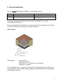
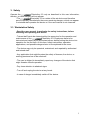
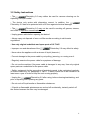
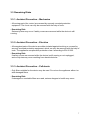
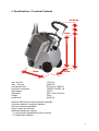
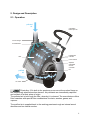
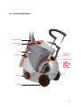
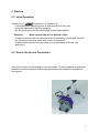
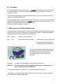
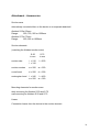
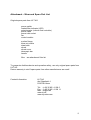
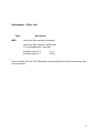
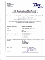
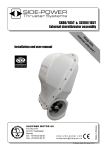
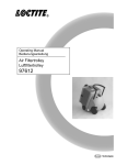
USER MANUAL
Filtertrolley 2.0 MED
Table of contents
1.
Preface
3
2.
Usage and Application
4
3.
Safety
5
3.1. Workstation Safety
3.2. Safety Instructions
3.3. Remaining Risks
3.3.1. Accident Prevention – Mechanics
3.3.2. Accident Prevention – Electrics
3.3.3. Accident Prevention – Pollutants
6
7
7
7
7
7
4.
Specifications / Technical Features
8
5.
Design and Description
5.1. Operation
5.2. Parts Identification
9
9
10
6.
Start-up
6.1. Initial Operation
6.2. Device Set Up and Connection
6.3. Operation
11
11
11
12
7.
Maintenance and Filter Replacement
12
8.
Possible Malfunctions
13
Attachments:
Contact:
Accessories
Wear and Spare Part List
Filter List
14
15
16
ULT AG
Am Göpelteich 1
D-02708 Löbau
Tel.: (+49) 35 85 / 41 28 0
Fax.: (+49) 35 85 / 41 28 11
Mail: [email protected]
www.ult.de
www.ultjumbo.com
2
1. Preface
The ULT Jumbo Filtertrolley 2.0 MED is intended for use in situations where laser or
electrosurgical procedures generate surgical plume, viruses and bacteria in the form
of dust, floating particles, gases and fumes. This smoke can be a respiratory irritant
to the surgical team and to the patients.
In order to assure the safety of employees, law states: These materials have to be
removed from the air!
This is just the right task for the
Filtertrolley 2.0. It combines features
such as high mobility, low weight, and noiselessness in an optimal manner. These
qualities are made possible by innovative components and the use of synthetic
materials.
The device impresses with its functional, up-to-date, and appealing design.
It is suitable for hospital, clinic or doctor’s office environment.
Work without draft
The
Filtertrolley 2.0 removes air borne hazardous substances directly
from the place of their origin and filters them instantaneously. With supreme power.
With the lowest possible energy consumption. Noiseless and adaptable. The
extreme filter efficiency guarantees purest air quality. A loss of heat energy belongs
to the past.
The filtered air is instantly returned to the working environment – without any form of
draft.
Assignment decisive
A special feature: The
Filtertrolley 2.0 is a basic device designed for
many applications. It can be variably modified with different filters and suction
elements.
Fields of applications: medical laser surgery and electrocautery, laboratories,
sterizilisation rooms, patient’s awakening rooms, anaestesthesia rooms , dentist’s
surgeries.
3
2. Use and application
The
Filtertrolley 2.0 MED is a versatile filter device.
Type
Filter system
Use / application
MED
Multi-level filter-system
Medical laser surgery and
electrocautery
For proper application please consult the producer’s operation, user, and
maintenance instructions.
Every use beyond these instructions is not as agreed. The manufacturer is therefore
not liable for damages resulting from improper operation.
Filter system:
Prefilter carton F5
HEPA filter H13
Activated carton
Filter system:
multi-level filter
- pre-filter carton F 5
- HEPA filter H 13 (ULPA filter U 15 optional)
- adsorption - gas filter
The combination of pre-, absolute- and adsorption filters guarantees an efficiency of
more than 99% due to multiple cleaning stages, provided that the filter is maintained
and replaced regularly.
4
3. Safety
Filtertrolley 2.0 only as described in this user information;
Operate the
thereby, on hand dangers will not appear.
- The
Filtertrolley 2.0 is a state-of-the-art device and therefore
save to operate. Nonetheless, there are remaining dangers, which can appear
if untrained staff operates the device or if the user manual is not observed.
3.1. Workstation Safety
- Read the user manual, in particular the safety instructions, before
installing and operating this device!
- Trained staff has to be determined by the supervisor for the operation and
Filtertrolley 2.0. Employees have to be
maintenance of the
instructed and trained by an authorised person before putting the device into
operation for the first time. At this time, safety instructions, operation
applications, and possible dangers have to be explained to the users.
- The device may only be operated, maintained, and repaired by authorised
and trained staff.
- Any application that might threaten the safety of humans, the device, or
working premises has to be refrained!
- The user is obliged to immediately report any changes of the device that
might threaten its safe operation.
- Pay close attention to attached signs.
- Turn off and unplug the device at any break.
- In case of danger immediately switch off the device.
5
3.2 Safety Instructions
- The
Filtertrolley 2.0 may neither be used for vacuum cleaning nor for
siphoning off liquid media!
- The device only works with alternating current. In addition, the
Filtertrolley 2.0 has to be protected with a 6A fuse against electrical damage!
- The
Filtertrolley 2.0 may not be used for sucking off gasses, steams,
and dusts in explosive concentrations!
- Unplug power cable before opening the device!
- Always carry out disposal of worn out filter media according to valid waste
regulations!
- Use only original substitute and spare parts of ULT AG!
- Improper use and alterations of the
Filtertrolley 2.0 may affect its safety.
- Never clean the appliance with a stream of liquid (hose etc.).
- Prevent damage to the power cable by not pulling, jamming, or running over it.
- Regularly examine the power cable for symptoms of damage.
- Do not use the machine if its power cable is damaged in any way. Use only original
spare parts as a substitute for the power cable.
- Safety equipment for the prevention of accidents needs to be maintained regularly
in order to observe § 39, paragraph 3, VBG 1. A safety check has to be carried out at
least once a year in order to keep the unit running properly.
Filtertrolley 2.0 after using, before cleaning/maintaining, and
- Unplug the
prior to repairing and replacing any parts.
- Do not suck off liquid media or flammable substances.
- If liquids or flammable substances are sucked off accidentally, instantly switch off
the device because the filter may be damaged.
6
3.3 Remaining Risks
3.3.1. Accident Prevention – Mechanics
- All moving parts (fan, motor) are covered by securely mounted protection
equipment. The cover can only be removed with the help of tools.
- Remaining Risk:
Serious injuries may occur if safety covers are removed while the device is still
running.
3.3.2. Accident Prevention – Electrics
- All energized parts of the device are either isolated against touching or covered by
securely mounted protection equipment, which can only be removed with the help of
tools. The appliance complies with protection class I according to EN 60 335.
- Remaining Risk:
If safety covers are removed while the device is still running or not unplugged,
serious injuries may occur resulting from electrical stroke.
3.3.3. Accident Prevention – Pollutants
- Only filters suitable for the device may be used. Do not run the appliance without or
with damaged filters.
- Remaining Risk:
If damaged or unsuitable filters are used, serious dangers to health may occur.
7
4. Specifications / Technical Features
Max. 850 mm
530 mm
450 mm
max. air flow:
max. vacuum:
constant air flow:
electrical connection:
input power:
dimension:
weight:
noise level:
340 mm
170 m³/h
2,800 Pa
80 m³/h at 1,400 Pa
120/230 V/50/60 Hz
150 W
450 x 340 x 530 mm
18 kg
49 db (A)
material: ABS stroke tough (synthetic material),
chemical-resistant, corrosion-resistant
blow out direction adjustable
option: waste air business
additional equipment (option):
- V: continuously adjustable air flow controller
- F: loaded filter indicator
8
5. Design and Description
5.1. Operation
polluted
air
extendible
telescopic bar
suction flange
air distribution
filter
loaded filter
indicator
power switch
stepless
adjustable
air flow
controller
purified
air
fan
air outlet
Filtertrolley 2.0’s built-in fan produces a vacuum at the suction flange or
the respectively attached suction element. Air pollutants are immediately captured
and sucked off at their place of origin.
The polluted air is led trough the filter, whereby it is cleaned. The manufacturer offers
filter cassettes with special filter combinations for dusts, smokes, gases, and
vapours.
The purified air is supplied back to the working premises trough an internal sound
absorber and two lateral nozzles.
9
5.2. Parts Identification
suction flange
air-distribution
plate
filter
draw latch
loaded filter
indicator
power switch
fan
nozzle
wheel
10
6. Start-up
6.1. Initial Operation
Unpack the
Filtertrolley 2.0 and set it up.
- unlock the black draw latches on its side and take off the cover
- check the tightness of the filter cassette
- put the cover back onto the device and lock the draw latches
Attention:
Never operate the device without a filter!
- Connect the device with an electrical outlet of alternating current and 230 V/50
Hz. Protect the electrical outlet with a fuse of at least 6A.
- Check whether the device type meets your requirements and suits your
application.
6.2. Device Set Up and Connection
Set up the suction unit according to your work place. To safely capture all pollutants,
position the suction element close to the place where the hazardous substances
emergence.
11
6.3. Operation
Filtertrolley 2.0 to turn the device
Push the big black button on top of the
on. Check whether the connections are made properly and whether the blow-out
nozzles are open.
If your device possesses the optional airflow controller, you may adjust the suction
capacity with the potentiometer.
The optionally installed “loaded filter indicator” shows the current state of the filter. As
long as the LED glows green the
Filtertrolley 2.0 is in normal mode. The
filters are saturated when the LED changes to red.
Then proceed as described in section 7.
7. Maintenance and Filter Replacement
The maintenance confines itself to the check of the filter contamination state and the
replacement of the filter. Devices with the optionally installed “loaded filter indicator”
signal with their LED the required filter replacement.
LED: -green-
filter is in good condition
LED: -red-
filter replacement necessary:
- replacement of the pre-filter mat
If no improvement takes place:
- replacement of the whole filter
The picture illustrates a filter replacement in
lying position. Before the filter can be taken
out, the black draw latches have to be
unlocked, and the cover needs to be
removed.
Disposal:
professional; according to valid regional regulations
Attention:
The device has to be unplugged before repairs, maintenance, or
filter replacements are carried out!
- The device is subject to inspection for portable electrical equipment.
- After each use the unit may be wiped down with a damp cloth (a soapy solution or
germicidal may be applied sparingly)
12
8. Possible Malfunctions
Problem
Cause
Elimination of problem
- fan does not run
- no electrical power
- check mains voltage
- fan does not run
- malfunction of device or
control electronic
- repair by a specialist
(specialist dealer)
- not enough suction - filters are saturated
capacity
- air passage is blocked
(option “F” - LED glows
red)
- filter replacement
- check of air inlet and
outlet
- bad filtration
- filters are clogged up
(option “F” - LED glows - filters are not in the right
red)
position
- filter replacement
- check filter installation
(put it in the right position)
13
Attachment - Accessories
Suction arms
alternatively mounted either on the device or on separate desk/wall
Alsident S 50d: 50mm
Range:
550, 750, 950 or 1350mm
Alsident S 75d: 75mm
Range:
650, 900 or 1050mm
Suction elements
(matching the Alsident suction arms)
S 50
in mm
S 75
in mm
suction tube
l = 210
l = 310
l = 250
suction nozzles
w = 200
w = 250
round hood
d = 200
d = 200
rectangular hood
l = 245
w = 220
l = 420
w = 320
Mounting elements for suction arms
desk mounting for Alsident S 50 and S 75
wall mounting for Alsident S 50 and S 75
Hoses
Connection hoses from the device to the suction element
14
Attachment – Wear and Spare Part List
Original spare parts from ULT AG
power switch
loaded filter indicator (LED)
potentiometer (volume flow controller)
power cable
power inlet socket
fan
control module
suction flange
blow-out nozzle
draw latch
wheel
wheel cover
telescopic bar
handle
filter
see attachment filter list
To guarantee faultless device and operation safety, use only original spare parts from
ULT AG.
Device warranty is void if spare parts from other manufacturers are used!
Contact Information:
ULT AG
Am Göpelteich 1
D-02708 Löbau
Tel.: (+49) 35 85 / 41 28 0
Fax.: (+49) 35 85 / 41 28 11
Mail: [email protected]
www.ult.de
www.ultjumbo.com
15
Attachment - Filter List
Type
MED
Description
multi-level filter cassette (complete)
multi-level filter cassette - HEPA filter
H 13 and adsorption - gas filter
pre-filter carton F 5
pre-filter carton F 5
1 pc.
10 pc.
Use only filters from ULT AG! Otherwise, the specified filter quality and quantity may
not be reached.
16
ULTAG
Am Göpelteich1
OT Kittlitz
D-02708Löbau
IJLT
UM\A/ELT-
LUFTTECHNIK
EC r Declarationof Gonformity
annexll No. 1A
accordingto MachineryDirective20061421EG
Herewith,we declarethat the followingproducttype in its deliveredstatecomplieswith
the followingrelevantprovisions:
42lEG
EC-Machinerydirective 20061
compatibilitydirective2004/108/EG
Electromagnetic
modifiedwithoutour approval,
lf the abovementionedmachineis technically
shallno longerbe applicable:
thisdeclaration
Description
of machine:
Absaug-und Filteranlage
Type:
2.0| 2.1| 2.2
JumboFiltertrolley
SeriesNo.
Appfiednationaltechnical
standards
andspecifications:
20YY...
(Year- Number)
DIN EN ISO 12100part,2
DINEN ISO 13857
DINVDE l OOO
DtNEN 60204-1
of the technicaldocumentation
KarlUllweris the authorized
representative
for completion
Address:
ULTAG
KarlUllwer
Am Göpelteich1
D-02708Löbau
place,date
Löbau,
02.01
.2012 U LT AG
-
Am Liopetretcn't ut Kmtnz
D - O27OB
Löbau
signature:
F-
tr
Telefon +49(0)3585I 41 ZB-O
+49(0)3585I 41 ZB il
^ Telefax
.7
V- ttttathz
[email protected]€.www.ult.de