1
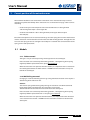
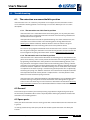
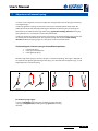
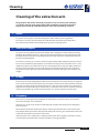
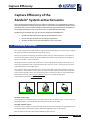
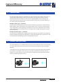
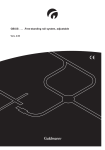
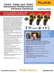
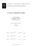
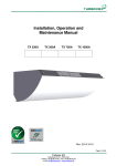
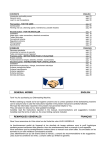
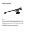
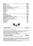
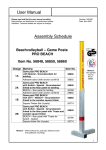
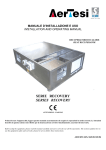
User’s Manual
A cleaner working environment
User’s Manual
for Alsident® System Extraction arms
With Alsident® System we focus on producing extraction arms of high quality with
long duration.
Alsident® System Extraction arms require a minimum of maintenance and are easy
to clean.
The design makes the extractopm arm self-supporting and provides a unique user
friendly extraction arm which is easy to clean.
Read this manual and follow the advice and guidance given on the operation and the
capture efficiency and your extraction arm will be of great use in many years to come.
Further information is available on www.alsident.com or by contacting your supplier.
Contents
1. System Overview.......................................................................................2
2.
Guide to technical terms........................................................................3
3.
Correct position of the extraction arm..............................................4
4.
Operation of the extraction arm..........................................................5
5.
Capture efficiency.....................................................................................5
6.Troubleshooting........................................................................................6
7.
Adjustment of internal springs............................................................7
Right reserved for modification of design and measurements. Alsident® System A/S . Finlandsvej 10 . 8450 Hammel . www.alsident.com
1/7
User’s Manual
A cleaner working environment
1. System Overview
Type
System
Diameter
of pipes
System 50
Ø50 mm
•
•
System 50 Flex
Ø50 mm
•
•
System 63
Ø63 mm
System 75
Ø75 mm
•
System 75 Telescopic
Ø75/Ø100 mm
•
System 100
Ø100 mm
•
Aluminium (AL)
Antistatic (AS)
Chemical Resistant (CR)
•
•
•
•
•
1.1 Type of Material
Aluminium (AL):
Extraction arms of aluminium are suitable in specified areas with
no requirement to chemical resistance or conductivity.
Antistatic (AS):
The antistatic extraction arms are suitable in ESD areas and ATEX
areas (Systems 75 and 100) where conductivity is required. Find
more information on the approvals in Test reports and Mounting on
our website under Technical support.
Chemical Resistant (CR):
These extraction arms are suitable in aggressive working areas with
special demands to chemical resistance in relation to work with
aggressive chemicals.
Right reserved for modification of design and measurements. Alsident® System A/S . Finlandsvej 10 . 8450 Hammel . www.alsident.com
2/7
User’s Manual
A cleaner working environment
2. Technical Terms
Socket pipe
Middle joint
B-Pipe
Small thumbscrews
Socket joint
A-Pipe
Thumbscrews
Wing for damper
Joint with damper
Right reserved for modification of design and measurements. Alsident® System A/S . Finlandsvej 10 . 8450 Hammel . www.alsident.com
3/7
User’s Manual
A cleaner working environment
3. Correct position of the extraction arm
We recommend before use to check that the extraction arm is mounted correctly. Incorrect
mounting may affect the flexibily of the extraction arm. See illustration on page 3 of the correct
mounting.
• Check on the joint with damper that the small thumbscrews are facing forward
and the wing for damper is to the right side.
• Check that the Alsident® label is facing forward (on the pipe above the joint
with damper).
One of the consequences of an incorrect mounting is that the spring will not come into function
and the extraction arm will therefore sink from the intended working position. Through time this
will cause the spring to loose its strength irretrievably. To re-establish the correct function of the
spring, it will need replacement.
3.1 Models
3.1.1. Table mounted
This type is easy to correct by turning the two pipes over the socket pipe.
If the extraction arm cannot keep the working position, a strengthening of the spring
might help before replacement of the spring (See section 7).
When the extraction arm operates two work stations, it is important that it is rotated on
the socket pipe between the work stations – DO NOT turn the extraction arm up and
behind the socket pipe.
3.1.2 Wall/Ceiling mounted
Changing an incorrect mounting of wall- og ceiling mounted extraction arms requires a
demounting of the extraction arm.
Caution:
The internal spring will be damaged by turning the extraction arm down backwards
below the bracket and socket pipe. The extraction arm has to be
demounted from the bracket and reversed UP above the socket joint.
If the extraction arm cannot keep the working position, a strengthening of the spring
might help before replacement with a new spring (See section 7).
When the extraction arm operates two workstations, it is important that the extraction
arm is rotated in the bracket – DO NOT turn the extraction arm down and behind the
socket joint.
Right reserved for modification of design and measurements. Alsident® System A/S . Finlandsvej 10 . 8450 Hammel . www.alsident.com
4/7
User’s Manual
A cleaner working environment
4. Operating the extraction arm
The extraction arms are easy to position at the pollution source and can just as easy be repositioned to a
new work situation or rest position when not in use.
The socket joint rotates freely from side to side
(only limited by the surroundings) and up/down.
The middle joint rotates upwards and downwards
and the joint with damper at the hood also rotates
around the pipe in a limited angle. The joint with
damper also rotates upwards and downwards and
the hood rotates in a limited angle. This gives a very
high mobility and flexibility.
The thumbscrews on the sides of the joint may be
loosened or tightened depending on how much friction is needed to keep the extraction arm in position.
The finger screws are to be tightened according to
requirement if they get loose because of frequent
movement and positioning of the extraction arm.
The more the thumbscrews are tightened, the more
force is needed to reposition the extraction arm.
Where large friction is necessary we recommend
loosening the thumbscrews slightly before the extraction arm is repositioned.
5. Capture efficiency
To ensure that the planned/necessary air volume is extracted we recommend you to get a test
report from your installer in order to document the actual air volume. Where more extraction
arms are used simultaneously, you must ensure that there is sufficient air volume available on
the number of extraction arms in concurrent use as planned with the installer.
By following three simple rules you can achieve the best possible efficiency:
1. Position the hood correctly in relation to the pollution source
2. Choose the right hood for the specific type of pollution
3. Position the hood as close to the pollution source as possible
Find more on this subject under Technical support and download the document
Capture efficiency under Maintenance.
Right reserved for modification of design and measurements. Alsident® System A/S . Finlandsvej 10 . 8450 Hammel . www.alsident.com
5/7
User’s Manual
A cleaner working environment
6.Troubleshooting
6.1. The extraction arm cannot hold its position
If the extraction arm is in a stationary rim position it can happen, that the extraction arm will
rise or sink from it working position. Several things can cause this. Below you can see a short
description:
6.1.1. The extraction arm sinks from its position
If the extraction arm is extended far from its mounting point, it is very likely that more
friction in the joint is needed to prevent the extraction arm from sinking. Therefore the
thumbscrews must be tightened.
If the point of extraction exceeds the specified working area of the extraction arm, the
extraction arm is either too short or the mounting point is wrong (download our
Working Areas from the website). The best solution is either to choose a longer extraction arm or to move the mounting point closer to the pollution source.
The internal spring might be weakened when the extraction arm is used in a rim position
for a long time causing the extraction arm to sink from its position. Here the solution will
be to strengthen the spring. Read more under section 7 Adjustment of internal spring.
6.1.2 The extraction arm rises from its position
If the extraction arm is bent under itself towards its mounting point, more friction in the
joint is also necessary, in this case to prevent the extraction arm in rising from its position,
by tightening the thumbscrews. If this position is the intended working position, a too
long extraction arm might have been chosen or the mounting point is wrong. A shorter
extraction arm or moving the mounting point further away from the pollution source will
be the best solution. A position in the lowest working area can make some of the models
rise upwards as the internal spring is a bit too strong for this position. This is adjusted by
weakening the spring a bit. Hold the extraction arm in both hands and push it below the
wanted position towards vertical position a couple of times - until the position is held.
Make sure not to weaken the spring too much.
If the extraction arm is positioned within the specified working area, the problem might
be that the O-rings in the joints have lost their friction due to soiling from oil, glue or
similar. In this case the O-rings are to be cleaned as described in the document Cleaning
of the extraction arm which can be downloaded from our website under Maintenance.
6.2 General
Please contact your installer if you need help solving any problem. It might be of great help to
the installer if you would be able to send a couple of photos showing the problem and the entire
extraction arm in working position.
6.3 Spare-parts.
Some parts of the extraction arms are wearing parts with a shorter lifetime than the extraction arm
in general.
It is always possible to buy new spare-parts for the Alsident System extraction arms from your
installer.
Right reserved for modification of design and measurements. Alsident® System A/S . Finlandsvej 10 . 8450 Hammel . www.alsident.com
6/7
User’s Manual
A cleaner working environment
7. Adjustment of internal spring
In certain cases it might be necessary to adjust the strength of the internal spring by weakening
or strengthening it.
In order to tighten the spring, the extraction arm must be demounted from the bracket. The
socket joint must be dismantled by removing the thumbscrew from the joint and pulling the
threaded stay out. Now bend the legs of the spring against the winding direction making the
spring effective at an earlier point. See the illustration below.
In order to weaken the spring, the extraction arm must also be demounted from the bracket and
the socket joint must be dismantled. The legs of the spring must be bent in the winding
direction to affect the spring to grip at a later point. See the illustration below.
The below figures show the spring in three different positions;
1. a weakened spring
2. a spring in normal position
3. a strengthened spring
Bend the legs of the spring in a distance of app. ¼ x h from the winding. The angle ‘v’ depends on
the need for strengthening/weakening of the spring. It is advisable to bend stepwise (e.g. 5⁰) and
frequently make a test of the spring.
Spring for table mounting
Spring for wall and ceiling mounting
For all three springs apply:
a spring is weakened by bending the legs in the winding direction.
a spring is strengthened by bending the legs against the winding
direction.
Right reserved for modification of design and measurements. Alsident® System A/S . Finlandsvej 10 . 8450 Hammel . www.alsident.com
7/7
User’s Manual
A cleaner working environment
Demounting of gas spring
Gas springs are mounted on the longer models of Systems 75 and 100.
Especially during a thorough cleaning of the extraction arms, it may in some cases be
necessary to remove the gas springs. During this process it is important to put the
extraction arm into the right positions in order to prevent damage to the gas spring
and the extraction arm.
1. Demounting gas spring
To prevent damages to the gas spring and the extraction arm it is important to position
the extraction arm in a way that takes the pressure off the gas spring and leaves it inactive when
demounting and mounting the gas spring.
1.1 Demounting gas spring on socket pipe
The gas spring on a wall or ceiling mounted extraction arm is a pull-spring. It is important to
push the A-pipe up towards the socket pipe as far as possible leaving the gas spring inactive. Now
you are able to demount the gas spring by removing the thumb screws from the clamp rings.
Warning: The extraction arm will not hold the upright position without the gas spring.
On mounting the gas spring, the A-pipe must be pushed up towards the socket pipe until the
gas spring fits easily onto the two clamp rings. It is impossible to extend the gas spring during
the mounting. Due to the strength of the gas spring it is only extendable while mounted on the
extraction arm.
The gas spring on a table mounted extraction arm is a push-spring. It is important to push
the A-pipe towards vertical position until the gas spring is fully extended in order to make it
inactive. By removing the thumb screws from the clamp rings you can now demount the gas
spring.
Warning: The extraction arm will not hold the upright position without the gas spring.
On mounting the gas spring, the A-pipe must be pushed towards vertical position until the gas
spring fits easily onto the clamp ring on the B-pipe and the angle bracket on the middle joint. It is
impossible to contract the gas spring during the mounting. Due to the strength of the gas spring
it is only contractable while mounted on the extraction arm.
1.2 Demounting gas spring on middle joint
On all extraction arms this gas spring is a pressure-spring. It is important to extend the B-pipe
upwards as far as possible until the gas spring is fully extended on order to make it inactive. By
removing the thumb screws from the clamp rings you can now demount the gas spring.
Warning: The extraction arm will not hold the upright position without the gas spring.
On mounting the gas spring, it is important to adjust the angle between the A- and B-pipe until
the gas spring easily fits onto the clamp ring on the A-pipe and the angle bracket on the middle
joint. It is impossible to contract the gas spring during the mounting. Due to the strength of the
gas spring it is only contractable while mounted on the extraction arm.
Right reserved for modification of design and measurements. Alsident® System A/S . Finlandsvej 10 . 8450 Hammel . www.alsident.com
1/1
Cleaning
A cleaner working environment
Cleaning of the extraction arm
Polypropylene (PP) can be cleaned by using almost any commonly used detergent
or ordinary cleaning spirit. Polypropylene (PP) and PETG are not to be exposed to
temperatures above 90⁰C therefore the parts cannot be sterilized by autoclave.
1. Hoods
For general cleaning: Use a common detergent or other ordinary cleaning product.
For intensive cleaning: Do not expose PP and PETG hoods to temperatures above 90⁰C.
As mentioned, the hoods can be wiped by using ordinary cleaning spirits.
2. Joint with Damper
For general cleaning: Wash the joint with damper with a detergent or other ordinary cleaning
products. We recommend once in a while to take the two half joints apart by loosening one of
the fingerscrews on the joint and pulling out the threaded stay. Then it is possible to clean the
O-ring as described below.
For intensive cleaning: It is necessary to take the joint with damper completely to pieces. Please
be sure to reassemble the joint properly and mount it correctly on the extraction arm. It is very
important to put on the small washers at the 5 mm fingerscrews on the joint. When mounting
the joint on the extraction arm, the small fingerscrews must point forwards and the damper
wing must be to the right. If the joint with damper is turned the wrong way, the damper is not
airtight.
3.O-rings
The O-rings are made of polyethylene (PE) and are maintenance-free. If the O-rings are exposed
to oils or fats, the friction between O-rings and contact surfaces will be reduced and prevent the
extraction arm from holding the working position. In this type of environment we recommend
frequent cleaning of the O-rings. A thinner such as acetone or similar can be used for cleaning. In
order to clean the O-rings and the contact surfaces, it is necessary to take the joint apart.
4.Frequency
The necessary cleaning frequency depends on the pollutant extracted and the environment
where the extraction arm is mounted.
Generally, it is necessary to clean the hood/stub pipe and joint with damper more frequently
than the A-pipe.
We recommend frequent checking for dirt by removing the hood to take a look into the joint
with damper. When you remove the joint with damper for cleaning, we recommend also to take
a look into the B-pipe to check if it is dirty inside.
If the extraction arm is mounted in a working environment where hygienic demands are strict,
we recommend systematization and planning of the cleaning procedure.
Right reserved for modification of design and measurements. Alsident® System A/S . Finlandsvej 10 . 8450 Hammel . www.alsident.com
1/1
Capture Efficiency
A cleaner working environment
Capture Efficiency of the
Alsident® System extraction arms
To ensure that the planned/necessary air volume is extracted, it is recommended to ask for a
test report from the installer proving the actual air volume. If the installation includes several
extraction arms, you must check with the installer that the right amount of air is available on
the number of extraction arms in concurrent use, as planned with the installer.
By following three simple rules you can achieve the best possible efficiency:
1. Position the hood correctly in relation to the pollution source
2. Choose the right hood for the specific type of pollution
3. Position the hood as close to the pollution source as possible
1. Positioning of the hood
The various positions of a hood can be arranged in three groups ways: the vertical (a), the angled
(b) and the horizontal (c) position of the opening (see ill.)
Many users position the opening horizontally which is the less efficient position. It is important
to consider the optimal position of the hood before the hood is chosen, because many types of
hoods are suitable in various positions.
The dispersion characteristic of the pollution is essential for postitioning of the hood. There are
many types of pollution with various dispersion characteristics such as swirling dust, hot steam,
soldering fume,heavy and light gasses.
The vertical and the angled positions are in general more efficient than the horizontal position
as they both – especially the vertical position – obtain a better capture zone because of the horizontal surface (Coanda-effect). The horizontal position normally less efficient. You will find more
information in our test report Capture efficiency which can be downloaded from
www.alsident.com under Technical Support.
(a) Vertical position
(b) Angled position
(c) Horizontal position
Example 1: Heavy gas
Heavy gas quietly evaporating will lie on a flat surface/table and disperse over it. In this case, the
optimal position is a vertical position of the hood on or close to the table.
Example 2: Warm vapour
However, a warm vapour rises upwards with some velocity. In this example an angled position of
the opening above and possibly slightly behind the pollution source is preferable.
Both examples lead to the choice of two different types of hood.
Right reserved for modification of design and measurements. Alsident® System A/S . Finlandsvej 10 . 8450 Hammel . www.alsident.com
1/2
Capture Efficiency
A cleaner working environment
2. Choice of hood
The individual types of hood are suitable for one, often two of the three options. Generally, we
recommend the dome hoods as they are well suitable in the angled or horizontal position,
whereas the flat screen is better for a vertical or an angled position. Due to the design, the
square hood can be placed naturally in all three positions, but obtains the highest efficiency at
the vertical and the angled position.
Example 1 (heavy gas) – continued:
Several hoods are suitable for the position with vertical opening. The precise number of these
hoods depends on the system (50, 63, 75 or 100). The flat screen is available in all four systems
and is designed for a vertical opening and a position on or near to a horizontal surface (table).
In this position the flat screen hood creates a draught across the table directing the heavy gas
towards the hood.
Example 2 (warm vapour) – continued:
Several hoods are suitable for the angled position of the opening; e.g. the flat screen hood; but
with this combination of position and pollution, a dome hood could also be a good choice. The
size of the dome hood depends on the size of the pollution source.
3. Distances and cross-flows
The capture efficiency is also influenced by the distance to the pollution source and sorrounding
air currents. This means that the closer the hood is placed to the pollution source, the higher
efficiency.
It also means that it is advantageous to place the hood in the moving direction of the pollution.
For example if a cross-flow in the room e.g. cold air from a window over the table leads the
pollution in a certain direction, you place the hood in order to take advantage of the direction
and the speed of the pollution (see ill.).
Right reserved for modification of design and measurements. Alsident® System A/S . Finlandsvej 10 . 8450 Hammel . www.alsident.com
2/2