1
VIP MK3 / VIP SYSTEM3
USER MANUAL
SECURITY
•
This instrument was manufactured and tested in conformity with IEC 348,
the standards DIN 57411 Part 1/VDE 0411 Part 1, .Protective Measures
for the Electrical Measuring Instruments. and left the factory in perfect
technical safety conditions. For the purpose of maintaining these
conditions and to guarantee safe operation, the user must adhere to the
indications and warnings contained in the enclosed operating instructions.
•
Before switching on the instrument it is necessary to verify that the
operating voltage and line voltage set on the instrument coincide.
•
It must be plugged into only a current tap with earth (ground) wire.
This protective action must not be eliminated by using an extension cord
without a protection conductor.
The electrical plug must be inserted before the measurement and
command circuits are disconnected.
•
•
Warning!
Any cut off of the protection conductor inside or outside the instrument,
or detachment of the protection conductor connection can cause the
instrument to become dangerous. No voluntary cut off is allowed.
•
During the opening of the covers or the removal of pieces with the
exception of the cases in which these operations are carried out
manually. live pieces can get skinned. The connection points can also be
live. Before any compensation maintenance. repair or replacement of
pieces. it must be detached from any power sources any time that it is
necessary to open it.
•
•
•
The capacitors can be loaded even after it has been detached from alI
power sources.
It must be guaranteed that the replacement protections used are of the
required amperage. The use of protections which have been repaired or
short-circuiting of the fuse carriers is not allowed.
After having determined that it can no longer operate safely, it must be
taken out o! service and secured against involuntary operation.
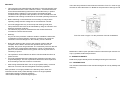
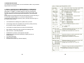
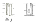
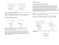
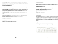
There are two protection fuses inside the instrument. Fuse F1= 5x20 1A type T
mounted on the instruments P.C. Board for the protection of the logic circuits.
Rear
Fuse
Fuse F2= 5x20 1A type T for the protection of the Ni-Cd batteries.
Maintenance and/or repair operations with the instrument open must be carried
only by qualified, authorised personnel.
A - OPERATOR SAFETY .
Read these pages carefully before installing and using the instrument.
A.1 - INTRODUCTION
The instrument described in this manual is designed for use by suitably trained
staff only.
Safe operation is no longer possible in the following cases -when the
instrument shows clearly visible damage -when it no longer operates
-after lengthy storage in adverse conditions
-after serious damage caused during transport.
2
1
Ali servicing and/or repairs which involve opening the instrument must be
carried out exclusively by skilled, authorised staff.
A.2 - SAFETY PRECAUTIONS
For proper, safe use of the instrument and for servicing and/or repairs the staff
authorised to carry out servicing and/or repairs must observe standard safety
precautions.
A.3 -SYMBOLS
READ THE INSTRUCTIONS
A.4 - PRECAUTIONS IN CASE OF MALFUNCTIONS
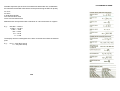
B.2.2 - SUPPLY VOLTAGE
The instrument can be supplied at a voltage range between 200V and
240 V; 50/60 Hz (100 V -120 V. 50/60 Hz on request).
For a supply voltage range 200 V- 240 V use fuses 80mA 250V type T
(160 Ma type T for 100V-120 V operations). Disconnect the power lead
before changing the fuse. The fuse holder is located on the rear panel
beneath the power socket. If the fuse requires replacement, proceed as
follows:
-Remove the fuse-holder lid using a screwdriver.
-Insert a new fuse with the same specifications and close the fuse
holder.
If it is suspected that the instrument is no longer safe, for example because of
damage during transport or use, it must be withdrawn from service and
precautions must be taken to ensure that it is not used by mistake. Call in
authorised technicians for checks and any repairs required.
B - INSTRUCTIONS FOR INSTALLATION
B.1 - PRELIMINARY CHECKS
On receipt of the instrument, check that it has not been damaged during
transport.
Ensure that only fuses with the same voltage and current ratings as the
originals are used.
Repaired and/or short-circuited fuses must never be used.
If any problems are noted, contact the ELCONTROL service network for any
repairs or replacements.
B.3 - BATTERY OPERATION
B.2 -SAFETY INSTRUCTIONS
B.2.1 -GROUNDING
Before any connections are made the instrument must be grounded by means
of the power supply plug, which must be inserted only in sockets complete with
ground connections.
Power lead extensions may only be used if these ensure that the power supply
(mains) connection is maintained.
3
A 5 V 1300 mA Ni-Cd battery (consisting of 4 elements of 1.25 V 1300
mA connected in series) will supply the instrument for 3 hours with the
internal printer and display illumination switched off. IMPORTANT
When the instrument is running on the battery the ground connection is
not required and therefore MUST NOT BE CONNECTED. The internal
battery automatically recharges in 48 hours when the instrument is
connected to the power supply (mains), or it can be recharged in about
60 minutes if the FBC1 module is connected to the socket provided.
N.B. Remember that when the FCB1 battery charger is used the
automatic power supply (mains) charging function is disabled.
4
1 DESCRIPTICN CF THE INSTRUMENT
1.2 EASY TO USE
1.1 WHAT IT CAN DO
This brief description may give the impression that use of the instrument
is very complex: in reality, procedures far measurements relating to most
of parameters are quite straight forward.
The VIP SYSTEM 3/ MK3 are the result of experience drawn from two
previous ELCONTROL instruments of the same type (the VIP and the
MICROVIP). whose excellent features they retains. However. they also
incorporate very important innovations which make them truly new
instruments.
They monitor alI three phases of a three-phase system.
The instrument is supplied by the factory already set up far monitoring
mast of the parameters relative to an electrical user.
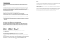
The supporting hardware supplied with the instrument comprises a set of
voltage measurement connection cables, three clamp meters far current
measurement and various accessories.
They are portable, light-weight device with built-in 40-column printer.
The VIP SYSTEM 3/ MK 3 can run on batteries and can measure no less than
81 electrical parameters with very high accuracy.
The VIP SYSTEM 3 / MK 3 and their accessories are preset with default
program data ready for immediate operation: they can be used straight
away to measure electrical power in Low Voltage systems (up to 600
Volts between phases and neutral) with phase current up to 1000 Amps.
In particular, the VIP SYSTEM 3/ MK 3 are capable of measuring parameters
not generally covered by an instrument of this type: they measure harmonic
distortions; indicate average values and record maximum readings for various
parameters; they measure and print out active and reactive power consumption; and record micro interruptions in the power supply (mains) and the
duration of longer interruptions.
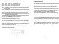
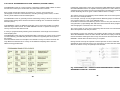
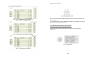
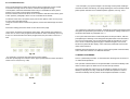
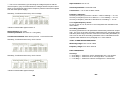
When the instruments are switched on, the measurement cycle starts
immediately and the display shows the first measurement page covering
three phase voltage. current. active power and CO~ parameters (see fig.
1.1 ).
The built-in printer is capable of printing measurement data on request and
can provide automatic print-out of the sequence of measurements relative to
any four parameters selected by the operator.
The instruments. printers can also provide bar graphs plotting 2 of the
parameters measured: they also provide rapid print-out of the value of those
parameters which cross the alarm thresholds and monitor their development
with frequent print-out until they come back inside the preset limits.
Alarm monitoring is made more effective by two RELAY outputs activated
when an alarm threshold is crossed.
All setting and selection procedures are carried out by means of a small
numerical keyboard and 4 function keys on the front of the instrument.
The function key with the symbol relating to the parameter required is
pressed to call up one of 10 different display pages, which show the 81
parameters the instrument is capable of monitoring.
6
5
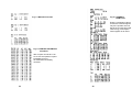
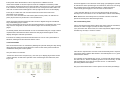
The measurements displayed (updated every second) are the following
Page 1 -Voltage, current, Cosø, three phase power.
Page 2 -Voltage, current, Cosø, power of phase L 1 (R)
Page 3 -Voltage, current, Cosø, power of phase L2 (S)
Page 4 -Voltage, current, Cosø, power of phase L3 (T)
Page 5 -Three voltages, neutral current, frequency, phase rotation of each phase
and three-phase
Page 6 -Instantaneous, average and maximum active power of the three phases
and three-phase
Page 7 -Instantaneous, average and maximum apparent power of the three phases
and three-phase
Page 8 -Instantaneous, average and maximum reactive power of the three phases
and three-phase
Page 9- Percentage harmonic distortion of the three phases and three-phase.
Page 10- Active and reactive power consumption, average Tg and average Cosø
of the three phases and three-phase.
1.3 HIGHLY VERSATILE
The main feature of this instrument, and the factor which makes it unique of
its kind, is its outstanding versatility and expandability.
The range of parameters monitored can be extended: for example. a special
interface provides current measuring capacity from 30 mA to 999 kA.
Other interfaces allow accurate readings to be obtained even with current
transformers (CT) other than the clamp meter provided. with different ratios.
In the same way, a special interface can be combined with the system's
voltage transformers (VT) for medium voltage measurements.
Direct current measurements can be made using a special interface and
clamp meter.
The measurements shown on the display can be printed by pressing the function
keys under the word PRINT in the last line of the display.
The VIP SYSTEM 3 / MK 3 can be connected to the telephone line using a
MODEM device to permit remote processing of data from a number of analyzers.
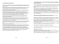
The next function key (beneath MENU) is pressed for access to the function
programming and measurement selection procedure.
A special accessory (MEMORY PACK) allows a larege number of measurements to be stored and then transferred to a remote printer or a computer.
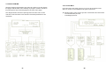
Even if we are now presented with a very large range of options, management of
these procedures is very simple thanks to the menu's tree structure. the operatorinstrument dialogue.
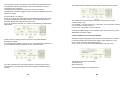
Movement through the tree structure is by means of the numerical keys and the
function keys. The specific function of the function keys are always indicated on the
last line of the display page. (See Fig. 1.2)
Finally, the VIP SYSTEM 3 can be used to measure different types of parame
ters far specific purposes through the installation of special BLACK BOXES.
The BLACK BOXES for measurement (by means of a prometer ) of temperature in the range from -20 o C. to + 200 o C (- 4 o to + 424 °F) ., and of
system leakage current, respectively, are already available.
For example, the function key located under "BACKPAGE" is pressed to turn back
one page in the MENU branch, while the function key under IIMEASURE" takes the
operator back to measurement page 1.
7
8
1.5 DESCRIPTION
1.4 FEATURES AND APPLICATIONS
The VIP SYSTEM 3 / MK 3 are therefore intended to provide electricity consumers
with in-depth information about their plant. But they are equally useful for design
engineers, fitters, service technicians and electricians for faultfinding, repair and
restructuring in plants already in operation.
The VIP SYSTEM 3 / MK 3 can be used in the following applications:
Load mapping
Overload reduction with correspondingly reduced current leakage
Checking new buildings and processes for design loading Improving safety
standards through overload identification
Accurate resolution of power factor correction problems.
Elimination of load peaks
Time period monitoring for optimum tariff utilisation
Monitoring high frequency marine and avionics supplies
DC measurement
PWM/PAM monitoring
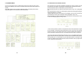
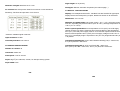
DISPLAY
KEYBOARD
MULTIFUNCTION FUNCTION KEY
The function keys have different
functions depending
upon the specific display page.
PAPER ADVANCE
ON / STANDBY SWITCH
ALARM RELAY
OUTPUTS
RS232 OUTPUT
INTERFACE CONNECTION FOR
AUXILIARY MEASUREMENTS
DISPLAY CONTRAST
REGULATION
POTENTIOMETER which
depends upon the inclination of
the instrument with respect to
POWER SUPPLY (MAINS)
(with built-in fuse)
the observers position
RAPID BATTERY CHARGE by means
of the FBCI optional accessory,
which is inserted between the line
and this point of the instrument.
The battery is recharged in on hour.
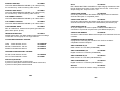
SELECTION ANG PRESETTINGS CARRIEQQUT ON THE KEYBOARD
KEY NUMBER for guided Selection inside the MENU
to Insert chosen presettings
KEY SYMB0L indicated to what measurements the
measurement display page refers (In this case [=
Three-phase measurements of (V-I-Cosø-KW on page
1)
CLEAR cancels the existing
presettings
9
10
ENTER confirm the posted
presettings the moves to the
following presettings
TOP VIEW
FUNCTION KEY FUNCTIONS AS INDICATED ON DISPLAY
Black Box compartment
Vip System 3 only
Measurement connections
Memory Pack
compartment
Vip System 3 only
As mentioned above. the function keys take on different functions
depending on the page shown on the display.
Four symbols on the bottom line of each page indicate the functions
provided at the moment by the respective function keys beneath them.
These are interpreted as follows:
-> Turn to next page.
<- Return to the previous page (tram measurement pages)
Printer
MENU Turn to the MAIN MENU page which is the starting point for
alI procedures.
PRINT Print-out of the readings shown on the display
DISPLAY Alphanumerical and graphic high contrast LCD display complete with
badlight for night-time illumination. The display is divided into 81ines of 40
characters: the first 7 are for menu messages and measurements; the last
indicates the functions of the 4 function keys beneath.
KEYBOARD Tactile keypad with 12 keys, 9 divided into two parts of different
colours, the upper section numbers used for menu selections and the lower
part the symbols of measurements shown on the display.
m k M Multiplier of the unit of measurement shown on the display.
M k m Divisor of the unit of measurement shown on the display
STOP Halts MEMORY PACK transfer.
BACKPAGE Return to previous page (from menu pages).
MEASURE Return to measurement page 1.
PRINTER Impact printer, 40 alphanumerical characters, 1.5 print lines per
second, capable of providing plotter and graph print-outs.
MODIFY Access to serial line modification page
MEMORY PACK External module which can be inserted in the instrument or in
a special compartment. connected by a connector. Contains a RAM memory of
128 or 512 kBytes with lithium buffer battery for storage of measurements.
which are retained for up to 5 years.-Suitable for VIP SYSTEM 3 onlyBLACK BOX Composition varies according to function. Generally comprises a
circuit with memory containing the application program. measuring method and
menu pages for the specific function. -(Suitable for VIP SYSTEM 3 )
11
RESET Access to RESET page (from survey programming page)
FORWARD Access to next measuring survey.
DISPLAY Selects display illumination adjustment page.
BEEP OFF Halts acoustic hot-spot tracer signal.
12
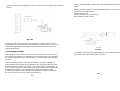
1.7 HANDLING THE INSTRUMENT
1.6 KlT SUPPUED WITH INSTRUMENT
The kit of equipment supplied with the VIP SYSTEM 3 / MK 3 is alI contained in a
sturdy case with foam inner lining for added protection. Fig. 1.3 below shows the
complete contents of the case and the location of the various accessories.
Adjustable handle
Used for lifting the instrument. AIso acts as an adjustable rest for the
instrument on the working surface.
The handle can be adjusted through 3200 from the rest position on a
series of catches.
Carrying-strap connecting hooks.
Used when the instrument is to be carried on the carrying-strap.
The hooks are connected to special slots on the instrument's handle.
Access to printer. By opening the pane' on the top of the instrument. Using
the thumbs, push on the ridged area on the lid in the direction shown in the
illustration.
POWER SUPPLY (MAINS) CABLE = Instrument feed cable
VOLTAGE CABLES = 4 cables (with double insulation) for voltage
measuring connections.
CLAMP METER = 3 clamp meters with range 0-1000 Amps
BELT = Instrument carrying-strap
INK RIBBON = Spare ink ribbon for printer.
PAPER ROLL = 2 spare rolls of paper for printer.
FUSES = 2 spare fuses
Spaces to house 3 MEMORY PACKS and 3 BLACK BOXES are also provided.
13
14
Changing the ink ribbon.
Open the printer compartment. Press on the word PUSH and slide out the ribbon.
Fit the new ribbon, pushing down slightly.
N
L1
L2
L3
for connection of neutral (if any)
for connection of phase R
for connection of phase S
for connection of phase T
There are also three three-pale connectors far connection of the three
clamp meters: these are marked L 1, L2 and L3 respectively.
Changing paper roll.
Open the printer compartment. Press on the word PUSH and slide out the ribbon.
Fit the paper as shown in Fig. 1.12 pressing the PAPER pushbutton several
times. Replace the ribbon and check paper alignment.
Access to connectors for connection of voltage measuring cables and clamp
meters. Open the panel on the top part of the instrument (procedure as for printer
compartment). This gives access to the connector panel as indicated in Fig. 1.14.
There are 4 single-pole connectors for the voltage measuring connections,
marked as follows:
The right-hand part of this section houses the compartments containing
the connectors far the Memory pack and Black Boxes.(VIP SYSTEM 3
only)
1.8 POWER SUPPLY ANO CONNECTION
The instrument is suitable for use on a power supply (mains) of 200 -240 V
50/60Hz. (100- 120 V 50/60 Hz on request). Connection is via the IEE
socket on the rear panel. (see Fig.1.15)
The instrument may also be powered by its built-in rechargeable battery:
the battery circuit is automatically connected when the power supply
(mains) plug is removed.
The instrument is supplied directly by means of the power supply (mains)
lead
and fuse with no intermediary switches.
The ON/STANDBY switch affects only the internal low-voltage circuit and
the battery. In ON position the instrument is operative. while in STANDBY
it is switched off but the battery- charging circuit continues to receive
power.
At this point it only remains to connect the instrument to the circuit at the
points where the measurements are to be made. For Low Voltage threephase systems, this involves simply connecting the voltage measuring
cables to the three phases and the neutral (if any) and the three clamp
meters to the three phases.
For a more complete description of the voltage measuring connections
required in the various cases please turn to paragraph 3.1.2.
15
16
The instrument will now start taking measurements when the switch contact
is made (ON position). The readings will be shown on the display in real
time, and updated every second.
For access to measurement pages 10 to 14 from any measurement page
press [E] followed by the key bearing the second figure of the number
(see Fig. 1.18)
1.9 STARTING MEASUREMENT FUNCTION
1.10 MANUAL PRINT-CUT CF MEASURED DATA
The measurements of alI the load's electrical parameters (and some other
non-electrical parameters) can be shown on the instruments display panel.
as explained in detail in paragraph 2.1.
For access to display measurement page 1 from other pages. simply press
the far right-hand pushbutton (beneath the word MEASURE at the bottom
of the page).
The bottom line of the display always indicates the function of each of
the 4 function keys immediately below. With a measurement page on the
display, the function key on the far right is pressed for manual print -out
of the measuring data shown on the display in that moment.
From page 1 access to pages- 2 to 9 is obtained by simply pressing the
corresponding numbered key (see Fig. 1.17)
Let us suppose for example that we are on any one of the measurement
pages: to obtain a print-out of the data measurement contained on page
9 press [9] to call the data required onto the display. The function key
under IIPRINT" is then pressed for print-out of the data shown.
Apart from manual print-out of one page at a time, the instrument can
provide overall print -out of all the latest measurement data ( contained
on the 14 display pages.)
To obtain overall print-out from any one measurement page, simply
press the function key under "PRINT" (far right) twice.
18
17
2 OPERATING OPTIONS
As mentioned in the introduction, the VIP SYSTEM 31 MK 3 can provide a
large number of functions.
2.1 DISPLAY INDICATION OF MEASUREMENTS IN PROGRESS
The first 10 display pages show the measurements of 81 electrical
parameters. In addition, on display pages 15 and 16 the instrument
indicates any measurements of non-electrical parameters made using
special transducers and the appropriate black boxes. (VIP SYSTEM 3
only)
If the operator has programmed the tariff time bands into which the day is
to be divided, display pages 11,12,13 and 14 will provide 64
measurements of active and reactive power, (average Coø and Tgø» in
the various time intervals.
The instantaneous readings are updated every second.
The average values are calculated over the time period preset by
the operator, and are updated continually.
The maximum measurements are stored until exceeded.
Each display measuring page indicates the following data:
Date and hour, continually updated.
Identification of phase or three-phase indication.
Parameter being measured: parameter reading and unit of
measurement.
Time band indication.
Display page number.
Functions of function keys beneath display.
19
20
2.2 INSTRUMENT PRINT OPTIONS
The printer incorporated in the instrument provides print -out of measured data
in one of the following ways:
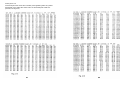
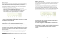
Manual print-out of the data which appear on the display
The operator obtains print-out of the data indicated on the display as shown in
fig.2.1 ; the tape also carries the date, time and page number.
Overall print-out (requested by the operator) by pressing twice the print function
key of alI the most recent measurements taken and stored by the instrument.
As shown in Fig. 2.2, overall print-out does not include average power and
energy readings for the various time bands if the operator has not made the
necessary presettings.
Timed local print. Automatic print-out of the measurements for 4 parameters
selected by the operator.
Under this mode the instrument stores 24 measurements (taken at a preset
time interval) and then prints them, without further operator instructions.
The operator selects the 4 parameters for timed local print from among the 63
electrical parameters (plus the auxiliary parameters).
This print mode is used to monitor a small number of parameters over relatively
long periods of time (many hours).
However, partial data may be obtained by interrupting the timed print sequence
and requesting immediate print-out of the measurements recorded so far (see
Fig. 2.2).
After this print-out (obtained using the FORCED PRINT procedure) the instrument starts taking a new cycle of 24 readings for the next timed print-out.
22
21
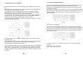
Fig. 2.3 OVERALL
PRINT-OUT
Fig. 2.1 Manual Print-Outs
Energy consumption values
for the time intervals appear
only if the operator has set
the times for each time band.
Total energy consumption
values appear in all cases.
Fig. 2.2 FORCED AUTOMATIC
Print-Outs
After 18 print records at.17.09
hrs 21 sec the operator request
immediate print-out
Of measurements already
recorded
23
24
2.3 TIMED LOCAL PRINT ALARMS
As has been seen, timed print-out is used above alI for long-term monitoring at
fairly long time intervals.
However, more intensive monitoring of phenomena which start and finish
during the interval between two print-outs may be appropriate.
In this case, the instrument must be set to take more frequent readings during
the periods in which it is believed that these phenomena may occur.
The timed print function therefore includes the option of setting periods of tirne
within which the print-out time interval is shorter.
This instrument function, which is activated using the alarm procedure, is called
hour alarms.
The print-out interval may also be reduced if the parameters being monitored in
the timed print-out mode pass the preset alarm thresholds (minimum or
maximum alarms).
In both cases the print-out ti me interval automatically changes to the alarm
interval, preset by the operator during SET UP
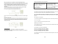
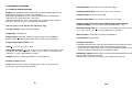
The print-out tape shown in Fig. 2.4 indicates how the print- out interval
becomes shorter during alarm periods. (The [ > * < ] signs in the string indicate
that the value has passed the alarm threshold. Respectively: > start of alarm, *
value still in alarm, > end of alarm).
Phase L 1 (V-1 N) voltage is in alarm state
(minimum and/or maximum alarm)
< ---4 Parameters selected for print-out
V-1 N L 1 phase voltage
W-Σ Average three-phase active power
VA-Σ Average three-phase apparent power
VAr-Σ Average three-phase reactive power
< ---< V-1 N voltage comes back above
minimum alarm value
< ---> V-1 N voltage passes minimum
threshold again
< ---* V-1 N voltage remains in minimum
alarm state. The interval between two
successive measures is now equal to the
alarm interval.
< ---k The units of measurement are kW
and kVA
Fig 2.4 TIMED LOCAL PRINT-OUT
2.4 RATE TIME BANDS
When the user is charged different tariff at different times of day, active and
reactive energy counters may be used to come into operation during
programmed time bands.
A time band is a period of the day which can be programmed between 00.01
and 23.59 hours, during which the energy values will be recorded not only on
the total meters but also on the time-band meters.
Time bands cannot be overlapped but intervals may be left between them. The
tariff band energy counters provide energy totals only during the period of the
day included in the band. and are reset by the meter rest procedure.
A maximum of 4 tariff bands can be set during the day, but the energy
consumed during the period not covered by the tariff bands can be obtained by
subtracting the band meter totals from those of the overall meters, giving a fifth
tariff band which may also consist of different periods distributed through the
day.
< ---The minus sign indicates excess
capacitive reactive power
PRINT-OUT OF A SECOND GROUP CF
MEASUREMENTS FOLLOWS AFTER A
TIME EQUAL TO 24 INTERVALS
Fig.2.5- PRINT-OUT OF POWER SUPPLY
INTERRUPTIONS
Microinterruption 200mS followed by
interruption of 36 Sec and return of power
supply.
25
26
2.5 INTERRUPTIONS
An interruption is any break in the instrument power supply which is in no way
related to the measurements being made. If the kind of monitoring is required for
one of the phase on which measurements are being made. the instrument must be
supplied by the circuit to which the voltage measurement cables are connected.
An interruption is a complete voltage failure (O Volts).
Interruptions in operation of any length are immediately recorded on the print-out.
Interruptions faIl into one of three different categories:
MICRO-INTERRUPTIONS
Power supply failure lasting between 2.5 mSec and 1 sec.
A line such as that shown below is printed out. identifying the date. hour, minutes
and seconds at which the micro-interruption occurred and its duration in mSec.
MIGRO INTERRUPTION DD:MM:YY HH:mm:ss xxxms
For interruptions lasting longer than one second, the instrument prints the date and
hour of the beginning and end of the interruption.
The print-out is of the following type:
MAINS INTERRUPTION
MAINS RETURN
DD:MM:YYHH:mm:ss
DD:MM:YY HH:mm:ss
If switched off, the instrument prints the date and time when it is switched off and
switched on again.
POWER OFF
POWER ON
DD:MM:YY HH:mm:ss
DD:MM:YY HH:mm:ss
In case of MICRO INTERRUPTIONS or MAINS INTERRUPTIONS the instrument
continues to run on its battery until these are exhausted, at which point it switches
off automatically.
Fig. 2.5 shows a print-out string for a short interruption in mains power supply.
Note that power supply is returned by an initial rapid re- establishment of the
switch contact (200 mSec) followed by a further re-establishment (36 Sec.)
27
2.6 PLOTTER
The instrument provides print-out in bar graph form of the measurements of two
parameters selected among those available: the plotter mode cannot be used
for maximum measurements and energy readings.
The instrument stores 24 measurements for each parameter at intervals preset
by the operator (sampling time). At the end of the sampling period the two
plotter graphs are printed one after the other.
The plotter zero and full scale values may be preset by the operator or
established automatically by the instrument.
As shown in Fig.2.6 , the tape also shows the date, the parameter monitored in
the graph, the hour when the readings were taken, the values of the 24
measurements in numbers, and the preset zero and full scale values.
If the parameter shown in the plotter graph has also passed one of the alarm
thresholds, the data print-out also indicates the alarm value.
When interpreting plotter graphs, remember that the instrument may give
negative measurements for some electrical parameters (- kW indicates active
power supplied to the circuit; -Coø indicates leading power factor. etc.)
These parameters may be represented in a plotter graph as shown in Fig. 2.8,
which shows the reactive power of a capacitor bank. This is first too low ( + KV
Ar) , and is then in excess of the load circuit requirement ( -KV Ar) in
succeeding periods.
It should also be remembered that the forced print procedure already described in the timed print section can be used to obtain immediate print-out of a
partial plotter graph (see Fig. 2.7).
The forced print procedure can also be used to synchronise the two plotter
functions, which are generally programmed at different times and thus start at
different times. This also occurs when the instrument is switched on, since the
forced print procedure is carried out automatically.
2.7 ALARM SIGNALLING
The instrument is able to indicate (by print-out) whether a parameter has
exceeded a maximum threshold preset by the operator (Maximum alarm).
In the same way. it is also able to indicate when a parameter passes below a
minimum threshold preset by the operator (Minimum alarm).
28
DATE
Fig.2.8
Plotter parameter
Plotter zero value=
213 V
Full scale low kVAr
Full scale excess kVAr
Plotter full
Scale = 259V
Plotter zone for kVAr
Absorbed by load
Minimun alarm
Voltage=210V
Voltage value
measured
Measuring time
Ploter zone for
excess kVAr
Sampling
Time = 1'
Maximum alarm
Threshold voltage
Fig.2.6 PLOTTER GRAPH FOR VOLTAGE OF PHASE L1 (R)
Fig.2.8 PLOTTER GRAPH OF EXCESS OR LOW
THREE-PHASE REACTVE POWER
Fig.2.7 FORCED PLOTTER PRINT-OUT
29
30
Alarm thresholds can be set for an unlimited number of the 49 parameters in
the list below:
Instantaneous voltage = 3 ph.to ph. voltages + 3 ph.to neu. voltages
Instantaneous current = 3 phase currents + neutral currents
Instantaneous active power = kW of each phase + three phase kW
Instantaneous CoSø = Cosø of each phase + three phase Cosø
Average active power = kW of each phase + three phase kW
Instantaneous apparent power = kVA of each phase + three phase kVA
Average apparent power = kVA of each phase + three phase kVA
Instantaneous reactive power = kVAr of each phase + three phase kVAr
Average reactive power = kVAr of each phase + three phase kVAr
Instantaneous distortion = Distortions for 3 phases and three phase distortion
Average distortion = Distortions for 3 phases and three phase distortion
Frequency
Auxiliary parameters
The operator is informed that a parameter has passed a threshold value by an
immediate alarm print. The instrument first prints the hour when the threshold
was passed. followed by the hour when the parameter came back within the
limit values, together with print-out of the maximum measurement (or minimum.
if a minimum threshold is passed) during the period in which the parameter was
beyond the threshold. To activate this function, the operator selects the
parameters to be monitored and presets the maximum and minimum alarm
measurements. The print-out shown in Fig. 2.9 refers to alarms for three phase
active power (kW-∑). for phase L 1 voltage (V-1 N) and the three phase power
factor (Cosø-∑).
Three phase active power is in alarm at values of > 50 kW; for phase L 1
voltage the maximum threshold is 240 Volts and the minimum 210 Volts. while
the three phase Cosø minimum alarm threshold is 0.85.
< kw-∑ power passes max. alarm threshold
< L 1 phase voltage is >240 V; it therefore enters
alarm state
< During the alarm max. V-1N was 253.8 V
< L 1 phase voltage falls below
240 V and therefore leaves the alarm state
< During the alarm max. kW-E was 57.39 kW
< The power value leaves the alarm state
The print-out shows that at 12:01: 14 hours the three phase active power
reached a value of 54.70 kW and therefore passed the alarm threshold (as
indicated by the symbol --> ). At 12:01 :42 hours the power reading fell to 48.3
kW. returning within the preset limits (indicated by < ---). The peak power
value during the interval between 12:01:42 hrs and 12:01: 18 hrs was 57.39
kW.
2.8 TIMED PRINT-OUT ALARMS
Alarms can also be signalled in timed local print-out mode. If a parameter
which passes an alarm threshold is also selected for print-out, the data printout will show a special symbol against the measurement.
If the operator has preset an alarm time (A.T.), which should be of small
duration and shorter than the print-out time (PT.) a number of measurements
may be printed during both the alarm periods and the timed print intervals.
Fig. 2.10 below is an example of various print intervals for a parameter set for
both timed print-out and alarm monitoring.
Max alarm
Hour alarm
Min alarm
Fig. 2.10
2.9 TARIFF TIME BAND ALARMS
One of the special alarms which the instrument is capable of signalling is
when power ratings are exceeded during the time interval when the load is
largest, which are generally the most expensive for the consumer.
The VIP SYSTEM 3/ MK 3 can be preset to provide alarm print-out when one
or more energy parameters (active, reactive or apparent power) exceed set
maximum levels in each of the time intervals into which the day can be
divided.
To activate this function, the operator must first set the times for the time
intervals in which monitoring is required. He then selects the parameters to be
monitored and the relative maximum threshold values.
During the period covered the third parameter monitored has never been in
alarm state.
Fig. 2.9 ALARM PRINT -OUT FOR TWO PARAMETERS
31
32
SETUP PRESETTINGS
2.10 RELAY ALARMS
Print-out of alarms. even if immediate. provides only retrospective monitoring.
They permit the problem to be diagnosed and appropriate measures to be
taken. but rapid signalling and intervention are not possible.
However, the VIP SYSTEM 3 / MK 3 are also fitted with two relay outputs for
immediate alarm signalling: these are activated respectively when two of the
selected parameters pass the alarm measurements.
The two parameters to be monitored are selected in the PERIPHERALS MENU,
from the parameters which have already been selected for alarm monitoring: the
alarm threshold values are those already preset.
The two relay outputs can be used far a wide range of different purposes: nearby
or remote warning lights or acoustic signals, emergency intervention on the loads
or plants etc.
2.11 PRESETTING PRINT-OUT
A number of operational presettings must be made before the instrument can be
used to make measurements and print out the relative data.
These are quite often settings which do not require modification: the operator can
therefore print all the preset values stored in the instrument and assess which data
and conditions can be retained and which require alteration.
Alongside the presetting values, other settings and programming are required.
These can also be printed out to allow the operator to check them through.
When presetting print-out is requested, the printer supplies a data print-out
containing the set up values and those for all the presettings made.
Fig. 2.11 shows a print-out with all the SET-UP presettings .
Measuring connections (3 wires -4 wires)
System voltage (Low Voltage -Medium Voltage)
Current full scale (to be set only if a C.T. other than the clamp meter
provided is used).
Voltage full scale (to be set only for Medium Voltage readings).
Cosø, to give the kVAr required for power factor correction.
Integration time (for average values)
Print time (between 1 and 99 minutes)
Alarm print time (if a print interval shorter than that set for the timed printout is required during alarm states).
time : hours xx minutes xx seconds xx
date: year xx month xx days
128k Memory pack (if inserted) Black Box (if inserted)
RS232; Presence of Remote printer and Host computer
Relay 1 : parameter being monitored; Type of alarm (min/max)
Relay 2: parameter being monitored; Type of alarm (min/max)
2.12 PRINT-OUT OF LOCAL PRINTER PRESETTINGS
Two presettings are required before the timed local print-out mode can be used
(normal print interval and alarm print interval). These are included in the SET
UP presettings.
The 4 parameters to be monitored through the print-out (3 parameters only if
energy parameters are selected) must also be set.
In the same way. the PLOTTER print mode requires setting of the sampling
time (i.e. the time interval between two readings indicated on the graph). and
the parameter to be monitored. The relative procedures will be described in full
in chapter 3 below. which will also examine the procedure for obtaining printout of all local printer presettings. Fig. 2.12 shows an example of a print-out
with data relative to the timed local print-out mode and the two plotters.
34
33
2.13 PRINT-OUT OF ALARM PRESETTING
To activate the alarm print-out function. the parameters for monitoring must be
selected and the minimum and maximum alarm thresholds set.
The alarm sensitivity. or the time for which a parameter may remain above or below
a threshold value before the alarm state is recorded on the print-out. must also be
set: chapter 3 will explain the selection and setting procedures.
As for the other selections and presettings, these values can be printed out to allow
the operator to check that the instrument is correctly programmed. Fig.2.13 shows a
print-out with alarm presettings relative to 3 parameters: this is interpreted as
follows:
1 st line Monitored parameter
Minimum alarm value
Maximum alarm value
V-1 N = L 1 phase voltage
210 Volts
240 Volts
2nd line Monitored parameter
Minimum alarm value
W-Σ= three-phase active power 50kW
3rd line Monitored parameter Three phase Cosø
Last line A/arm sensitivity for all the above alarms.
(To be more specific, an 80-column printer can give print-out of 7 parameters in normal
print and 13 in condensed print mode, while a 132-column printer can provide print-out
of 13 parameters in normal print mode.
This represents a considerable increase in the number of parameters which can be
monitored while the system is in operation.
Let's take a detailed look al all the functions which can be carried out using an external
printer:
Timed print-out of 7-13 parameters. The data print is preceded by a heading line
with alI the SET UP values, and a line with the symbols of the parameters being
monitored.
At the end of the sampling time (equal to the print time preset during the SET UP
phase), a line of measurement data is immediately printed. The two heading lines are
repeated after every 20 data lines.
Fig. 2.14 shows an example of timed print-out with compressed characters.
Manual print-out
The operator gives the instruction for print-out of a line with the latest measurements
relative to the selected parameters; (i.e. the print-out consists of the two heading lines
and one data line, as shown in the example below.
2.14 USE OF THE VIP SYSTEM3 WITH PERUIPHERALS
The number of functions offered by the VIP SYSTEM 3 / MK 3 can be considerably
increased by the use of peripherals such as an external printer, a Host Computer,
and signalling or intervention relays.
A remote printer can provide timed print-out of data relative to 7 -13 parameters
selected using a procedure which starts from the peripherals menu.
After the manual print-out the timed print procedure is reinitialised
35
36
Alarm print -out
The timed print-out mode also includes print signalling when any alarm
thresholds set in either the alarm menu or the timed print mode are
passed (see fig.2.15)
37
38
Alarm states are indicated on the print-out page as follows:
# beside the symbol of the parameter set far alarm monitoring
> beside the reading when the parameter passes the threshold
< beside the reading when the parameter returns within the acceptable limits
* beside parameter measurements which remain beyond the alarm thresholds.
During alarms, the print-out interval is changed to the one set as alarm interval in the
SET UP phase. The timed print-out mode also records and marks alarm states relating to
any time intervals programmed. If any programmed alarm threshold is passed, a line of
data is immediately printed. During any hour alarm periods (set by the operator) the printout interval remains the same as the alarm print interval preset during the SET UP phase.
Switch-offs
The external printer also signals any instrument switch-offs : the time when the
interruption occurs is indicated at the end of the first heading line.
(Power failures are not recorded).
The activities of the external printer do not interfere with the normal operation of
the local printer. meaning that the instrument can continue to carry out ali the
functions already listed without remote printer: display of measurement data;
manual print-out of display data; timed local print-out and plotter graph printout; alarm print-out; time interval alarms; interruptions etc:
A serial printer can be connected directly to the instrument by means of an RS
232 serial line.
To make this connection, the operator must enter the printer specifications in
the instrument and select the serial line speed and format.
As already seen, the print-out interval and alarm print-out interval are the same
as for the local printer; i.e. those set during the SET UP phase.
The parameters are selected by means of a different procedure (using the
peripherals menu), which is explained in paragraph 3.7 below.
Presetting and selection data can be printed out on the local printer; the table
shows an example of presetting and selection for the remote printer; as shown.
the parameters to be printed are the following:
L 1 phase voltage (V-1 N)
L2 phase voltage (V-2N)
L3 phase voltage (V-3N)
L 1 phase current (A-1 )
L2 phase current (A-2)
L3 phase current (A-3)
Three-phase active energy consumption (kWh-Σ;)
The print-out also indicates the instrument presettings relating to the remote
printer connected.
39
40
2.15 USE OF INSTRUMENT WITH HOST COMPUTER
The operating options which can be obtained by combining the VIP SYS 3/ MK 3
with a host computer offer extremely interesting possibilities.
AlI measurements taken and processed by the instrument can be stored in the
host computer, and can also be transfered to and stored on magnetic discs. The
instrument is connected to the host computer, as to the remote printer, by
~ means of an RS232 serial line .
A special transmission protocol inside the instrument allows most operational
..functions to be transmitted to the computer. For further information regarding
this protocol, contact the ELCONTROL offices to request the technical manual.
The only differences between the operational possibilities obtainable with the
host computer with the VIP SYSTEM 3 and the VIP MK3 concern the MEMORY
PACK and the BLACK BOXES, which are not available on the VIP MK3.
ELCONTROL are able to supply programs to allow the instrument to be
connected to IBM or compatible .personal computers. The program allows call-up
of measurement data, remote programming, transfer of MEMORY PACK data
(VIP SYSTEM 3 only) and management of the data archive.
The data can also be processed for special applications using standard programs
such as LOTUS, FRAMEWORK, EXCEL, DBASE etc.
Further details are available in the specific documentation on this subject.
41
2.16 MODEM CONNECTION FOR REMOTE MONITORING
The instrument can be connected to the telephone lines (public or internal
circuits) using the Modem system, to allow remote reading of the data obtained.
Connection by means of a dedicated telephone line can be considered as similar
to a direct RS232 serial connection, except for the control signals typical of
control of a Modem line but requires a fixed line 24 hours a day.
Connection by means of a public or switched line requires a simple telephone
line to which the Modem can be connected. In this case, apart from the Modem
connection costs, the user pays only for the time in which the connection is
active.
With the latter type of connection the difference between the VIP MK3 and the
VIP SYSTEM 3 becomes very clear.
With the VIP MK3 the user can only transfer current measurements and counter
values, while with the VIP SYSTEM 3 and the MEMORY PACK the operator can
store an entire day's data and transfer them during the night when telephone
costs are lower.
42
2.17 USE OF THE MEMORY PACK FOR SURVEYS (SYSTEM 3 ONLY)
The MEMORY PACK is a mass memory comprising a battery RAM CMOS on which
all measures made by the instrument at a preset interval are stored.
Each of this storage procedures is known as a "record", and consists of a
"photograph" of ALL the measurements, including average power values, counter
values, power failures and microinterruptions .
The MEMORY PACK is generally used for measuring surveys, where a "survey" is a
period of time during which alI the instrument's readings are recorded at fixed time
intervals (rates).
Two MEMORY PACKs of different capacities can be used: the smaller is of 128 K,
while the larger offers 512 K. The 128K MEMORY PACK is capable of storing 14
surveys and more than 649 records.
A survey is programmed by entering exact indications of the begin and end times
and sampling rate.
The MEMORY PACK may be programmed with a sequence of surveys to be carried
out automatically, provided they alI refer to measures regarding the same point in
the system.
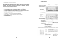
The chart below shows an example of 4 automatic surveys: as will be noticed, the
only difference between the 4 surveys is the different sampling rate in the four
different energy tariff bands.
If automatic measuring surveys are programmed with different time intervals
the 128K MEMORY PACK is capable of storing data for an entire week (e.g.
sampling every 10 minutes for 10 hours followed by sampling every 30 minutes
for the remaining 14 hours gives a total of 616 records in 7 days) .
The various surveys are generally not alI related to the same load system as is
the case in the example above.
For example, surveys can be programmed for different groups of loads within a
user system (see Fig. 2.20), or for different users.
In situations of this kind. the Memory pack is used to carry out manual surveys.
using the SET Up presettings with which the instrument has been programmed
and changing the connections for each survey.
The survey starts as soon as the measuring rate has been set and tinishes
when the operator ends the procedure.
In automatic surveys, the operator can program alI the surveys he requires or
which the MEMORY PACK can take off-site: ON SITE he simply connects the
instrument before starting the first survey and removes the instrument and
MEMORY PACK when the final survey is complete.
During manual surveys the operator must be present on site to make the
presettings and to start the survey: he must return on site at the time when he
wishes to end the survey and perhaps start another.
Fig. 2.20 EXAMPLE OF 5 SURVEYS WITH MEASUREMENTS TAKEN AT
DIFFERENT POINTS IN A SYSTEM.
43
44
2.19 PYROMETER; BLACK BOX FOR TEMPERATURE MEASUREMENT
(VIP SYSTEM 3 only)
2.18 SURVEY DATA PRINT-OUT
At the end of a survey, the data stored on the Memory pack is transferred back
into the instrument, which has previously been programmed to select some of the
data received.
From the instrument, the selected data is then transmitted to the external f printer
along the RS232 serial line. If an 80 column external printer is used, up
,t to 8 parameters can be selected for printing, while 132-column printers can
take up to 13 parameters (spaced print).
Together with these measurements, the Memory pack also stores and transmits
to the printer alI interruptions and micro- interruptions in its power supply.
Even after transferring the survey data, the Memory pack continues to store
these measures, meaning that the data relating to different parameters collected
during the same survey can later be transmitted: for example, the measurements for a second group of 8/13 parameters can be printed out.
At the end of the survey, the operator (if he wishes) can request print-out of
measurements for alI the parameters stored on the Memory pack, up to a
maximum of 64 parameters.
The advantage of using survey operation, apart from the availability of a large
amount of data, is that the operator can program the Memory pack off-site.
The instrument can then be connected to the circuit by staff unskilled in the use
and programming of the VIP SYSTEM 3.
At the end of the survey the instrument and Memory pack are removed and those
measures which the operator wishes to check and analyse are printed out offline.
While the survey is in progress, the VIP SYSTEM 3 can function as if the
Memory pack were not connected.
This means, for example, that the operator can still read the measurements for
the monitored parameters on the display and obtain manual print-out of the data.
He can also program timed local print-out for a maximum of 4 parameters,
request plotter print-out of 2 parameters, program alarm state print-out of any
parameter and request excess energy consumption for the various time bands.
At the end of the survey the operator will have at his disposal sufficient data / and
information (instrument measurements and survey data) for sophisticated
analysis of the electrical system being monitored.
45
A special compartment on the instrument can be fitted with a Black Box. which
is a specially programmed interface allowing the measurement of other parameters in addition to the electrical parameters typical of an industrial user
system.
The instrument's range of functions can therefore be expanded to include
measurement of any additional parameters for which the relative Black Box
and, naturally. measurement transducer are available.
This means that all the operational modes (display, print-out. Plotter graph
print-out). alarm state monitoring (with print-out or relay signalling). and the
survey monitoring options, can be applied to any of the additional parameters.
The standard electrical measurements and the new measurements can be
taken simultaneously.
This opens the instrument up towards a range of new applications, which
ELCONTROL intend to develop further in the near future.
At present, ELCONTROL have prepared the first Black Box for use with the
instrument, which measures the temperature of an object in the range from 20°C to + 200°C (-4°F to + 424°F) using a special pyrometer.
The pyrometer is an infrared gun which measures the heat radiation emitted by
the body and transducers this intensity into a weak signal.
The signal is then amplified and transmitted to the instrument by connection to
the rear AUX connector.
The Pyrometer Black Box contains a program which enables the instrument to
display and print the pyrometer's temperature measurements.
The temperature is displayed only in degrees Centigrade.
The temperature measurements obtained with the pyrometer Black Box can
serve two main purposes:
-Identification of hot spots:
In this case the zone under examination is scanned directly, checking the
temperatures of the various points on the display.
When the pyrometer identifies a point with higher temperature the instrument
provides a BEEP signal in addition to the display reading (see Fig: 2.21) .
46
-Precision checking of temperature in points of the plant (or the equipment) of special
interest.
The VIP SVSTEM 3/MK 3 can provide LmA monitoring in all the following
modes:
Display indication (page 16). Manual print-out (page or overall) Timed
local print-out. Plotter print-out.
Alarm state print-out.
Using a remote printer. With survey.
With activation of alarm relays.
Fig. 2.21
For this function the pyrometer is first positioned at a distance of 20-25 cm
(depending on the size of the body for monitoring). The pyrometer must then be
regulated as appropriate for the type of material and the surface area of the
heat-producing body.
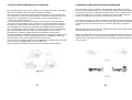
2.20 LEAKAGE CURRENT
The leakage current measurement (shown on the display and in print-out with
the symbol LmA) permits clear identification of any points where the insulation
is no longer efficient because of deterioration or contamination of the insulating
material.
This is an auxiliary function of the VIP SYSTEM 3. requiring a suitably programmed Black box and the special leakage toroid, which must be connected
to the instrument as shown in the fig. 2.21: the toroid cable is connected to the
AUX connector on the rear of the instrument. while the Black box is fitted in the
compartment provided. In the VIP MK3 the program for leakage current
monitoring is resident in the instrument and the toroid is simply connected to
the AUX connector by means of the special interface.
47
Fig.2.22
The toroid is connected at the point of the plant to be monitored so that
all the phase wires plus neutral pass through it.
48
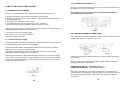
3.1.2 CONNECTION TO CIRCUIT.
3 USE OF THE VIP SVSTEM 3 and MK3
3.1 PRELMINARY PROCEDURES
The VIP SYSTEM 3 and VIP MK3 can be used far the following functions:
The upper part of the instrument houses a series of safety connectors for
the voltage and current connections.
The instructions which follow must be complied with; otherwise
measurement errors will occur.
1 -Display indication of alI electrical and auxiliary measurements.
2 -Print-out of measurements in various modes (manual print-out. timed print-out or
plotter graph print-out).
3 -Alarm print-out. activation of alarm relays.
4 -Use with peripheral units (remote printer or host computer.)
5- Storage of survey data on MEMORY PACK (SYSTEM 3 only).
The functions listed above are activated by different procedures, but the preliminary
operations below are required for alI functions:
-Connection of instrument power supply.
-Connection to the circuit to be monitored.
-Initial presettings procedures.
3.1 1 Instrument power supply .
Fig 3.2
VOLTAGE MEASUREMENT CONNECTIONS
The voltage measurement connection is made using the leads provided,
following the diagrams in figs. 3.3.1 and 3.3.2.
As has already been described in paragraph 1.8. the instrument can be powered by
the power supply (mains) or by a standby battery.
Remember that the battery charge will be sufficient for about 3 hours' operation
without print-out or illumination of the display.
The battery should therefore not be used when the instrument is functioning
unattended or during lengthy print-out sequences.
The battery will recharge in about 48 hours if the instrument is run from the mains
power supply. or can be rapidly recharged (about one hour) using the special FBC1
accessory connected to the power supply (mains) and to the connector on the rear
of the instrument (see Fig. 3.1).
Always check that phase rotation direction is respected when making the
connections.
The instrument checks this automatically on display page 5. where the
following messages are displayed:
PHASE ROTATION OK = Connection correct
PHASE ROTATION NOK = Connection incorrect
N.B. When connecting to circuits with voltage levels exceeding 250 V
(neutral phase) or with high DC currents, probes and test prods suitable for
the measuring point should be used. These are available as optional
accessories.
49
50
4-WIRE SYSTEM (THREE PHASES PLUS NEUTRAL)
The connections are made as shown in figure 3.4.
When making the connection it is vital to check that each clamp meter 15 connected
to the same phase of the corresponding voltage measurement.
A connection error will have significant effects. since an angle of 120 degrees will be
added to the phase shift angle between current and voltage.
The clamp meter can be connected without reference to current direction, since the
instrument itself will invert this if incorrect.
Program setup as explained in paragraph 3.1.7 , selecting "3- WIRE" connec
tion.
N.B.: A connection with 3 clamp meters as shown in figure 3.4 can also be
made in a 3-wire system without neutral.
In this case proceed as follows:
-Program "4-WIRES" in the set-up phase
-Connect the neutral to earth (ground)
A low neutral current reading will however be provided, caused by inevitable
small imbalances in the system.
3.1.3 SPECIFIC CONNECTIONS
C.T. OR CLAMP METERS OTHER THAN STANDARD
Program the set-up as explained in paragraph 3.1.7, selecting "4- WIRE" connection.
3-WIRE- SYSTEM (WITHOUT NEUTRAL)
Make the connections as shown in figure 3.5.
When making the connection it is vital to check that each clamp meter is connected to
the same phase of the corresponding voltage measurement. A connection error will
have significant effects. since an angle of 120 degrees will be added to the phase shift
angle between current and voltage.
The clamp meter can be connected without reference to current direction, since the
instrument itself will invert this if incorrect.
Connect the instrument neutral to the system earth (ground).
If using a C.T. ( current transformer) or measuring clamps other than the
clamp metres provided, the speciallNTA/1 or INTA/5 interfaces, available as
optional accessories, must be used.
1) Connect the C.T. secondary winding to the INTA/5 or INTA/1 interface (fig.
3.6.1).
2) Eliminate the short-circuit on the C.T. (Fig. 3.6.2).
3) Connect the interface to the instrument, always ensuring that voltage and
current inputs correspond (Fig. 3.6.3.)
IMPORTANT: Follow the connection sequences indicated carefully -otherwise the instrument may be seriously damaged.
51
52
MEDIUM VOLTAGE
VOLTAGE MEASUREMENT CONNECTIONS
For medium voltage measurements, the voltage of the three phase system
(generally of 3-wire type) must be obtained by means of two V.T.s (voltage
transformers) with secondary winding at 100 V, which are connected to the
instrument as shown in Fig. 3.8.1, ensuring that the voltage and current
connections are made to the correct terminals. Normally, the common of the two
V.T.s is connected to earth (ground), meaning that the neutral cannot be
connected to earth (ground). A Delta Star convertor of type DSC-MT (fig. 3.8.2) is
therefore required to create a false neutral.
Figure 3.7.1 shows two examples of connections with C.T. or clamp meter
other than those supplied as standard.
Program the set-up as indicated in paragraph 3.1.7, selecting "4- WIRE" or
"3-WIRE" as appropriate and program the C. T primary winding value.
SPECIAL CONNECTIONS (Not usual)
N..B...
The DSC-MT convertor, available as an accessory, is designed far use with V.T.s
only and can therefore withstand max. 120 VAC.
Program the set-up as explained in paragraph 3.1.7, selecting "MEDIUM
VOLTAGE" and "3 W IRE" and setting the V. T. primary winding voltage.
Figure 3.7.2 shows an example of a 3-wire standard connection with
transformer having star-connected secondary winding with centraI
connector earthed (grounded).
When using transformers with delta-connected secondary winding (Fig.
3.7.3) and thus without earthed (grounded) central connector (no neutral)
or with potential differences between the earth (grounds), a Delta Star
interface is required: this has to be capable of operating at phase to phase
voltage of the application.
53
In the case of V.T. with secondary value other than 100 V program a value
corresponding to:
V Primary * 100
______________
V Secondary
54
CURRENT MEASUREMENT CONNECTIONS
For medium voltage measurements C.T.s must be used; these are connected
to the instrument by means of an interface.
Normally, one C. T. terminal is connected to earth (ground) in common with the
others (Fig. 3.9.1, Fig. 3.9.2.).
SINGLE-PHASE MEASUREMENTS
For measurements on single-phase circuits. use the inputs of instrument phase L
1 only (current on connector L 1 and voltage between connectors L 1 and N, as
shown in Fig. 3.11).
The wires of the other phases must be connected together and to neutral to
prevent false measurements caused by the inputs in open-circuit condition.
Program the set-up as explained in paragraph 3.7.1 , selecting "4- WIRE"
connection.
AC/DC MEASUREMENTS
When using INTN5 interfaces remember that there is no galvanic separation,
meaning that the instrument ground is connected straight to the circuit. However, it must be ensured that there are no extra voltages between earth
(ground) and the instrument earth (ground), and in any case that no conditions
which may lead to instrument damage in any way are present. Otherwise, an
insulating transformer (Fig. 3.10.1) or the special SEPN5X3 (Fig. 3.10.2)
available as an accessory must be used.
When measuring on DC circuits or systems or those in AC with overlapping DC
components (such as inverters. U.PS.. rectifiers). Hall-effect clamps specially
designed for this type of measurement must be used: these are available as
optional accessories.
Connection to the instrument is by means of an ADAPTA-1V/1V adaptor as
shown in Fig. 3.12.1 (always using the L 1 phase inputs) and in Fig. 3.12.2 and
Fig. 3.12.3 for three-phase systems (always ensuring that voltage and current
inputs correspond).
The clamp meter can be positioned without reference to current direction since
the instrument itself will reverse this if incorrect.
The VIP SYSTEM 3/MK 3 does not require special presettings for AC/DC
measurements except for the normal set-up programming phases.
When using ordinary commercially-available Hall-effect clamps, remember
that the instrument will accept a maximum input signal of 1 V.
55
56
Alarm relay connection
The circuits of equipment without earthling must not be connected to the
alarm outputs.
For inductive loads install a suitable quenching circuit (diode if used in DC;
RC group of 33 ohm 0.1 F if in AC)
3.1.5 Auxiliary measurement connections
Signal input is by means of the AUX connector on the rear of the
instrument.
58
3.1.7 Initial presetting procedures
3.1.6 Switching on the instrument
The instrument is switched on by actuating the ON-STANDBY switch on the
rear.
After switching on. the following messages will appear on the display without
any operator commands being necessary.
1 -The display will fill up with alI the alpha-numerical characters available.
which will remain visible for several seconds. This indicates that the display
testing procedure has been carried out with positive results.
2 -The message TEST OK will then appear on the display and remain there for
several seconds. This confirms that the checks on communication with the
printer drive and measuring drive have given positive results.
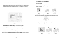
3 -The next display page relates to the optional operational modes. One of the
following two pages will appear
The initial instrument setting procedures are activated by following the instructions contained in the display page which carries the main menu.
The last line of each display page shows the functions of the function keys
below at that moment.
For example, on page 1 (see Fig. 3.18), if the function key under MENU (4th
from the left) is pressed the main menu appears on the display. The setting and
selection pages are then called up using a system simplified by the use of
operator prompts.
The procedure is as follows:
-The [O] key on the keyboard is pressed for access to the SET-UP display
page. -Key [ 1] on the keyboard is pressed for the display page for selection of
the type of circuit connection required (see Fig. 3.19) The choice is between a
star connection (4-wire three phase systems) and delta connection (3-wire
three phase systems).
The page shown in Fig. 3.17 may change depending on the optional present.
(SYSTEM 3 only)
If the operator intends to use one of these options. they must be inserted (and
removed when no longer required) with the instrument switched off.
4 -The display then shows measuring page 1.
N.B.: If the instrument has never been used , it will retain the factory presettings
(default data):4-wire connection, Low Voltage, full scales 1000 Amp and 600
Volts, Cosø = 1, integration time 15'. If the operator requires different settings,
the default settings must be modified using the procedure described in the next
paragraph.
59
For measurement on a single phase system, a star connection should be
selected.
Press [1] for 4-wire connection.
Press [2] for 3-wire connection.
60
N.B.: The presence of a number in reverse (white digit on black
background) indicates a previous connection type setting. If this selection
is to be confirmed, press the number indicated again to pass to the next
page. If a different setting is required, press the key with the new
number; the REVERSE character position will shift and the next page
displayed.
-The next display page (see Fig.3.20) allows selection of the voltage
level: Press [1] for systems at less than 600 Volts (L. V.)
Press [2] for systems at more than 600 Volts (M. v:)
Follow the indications in the chart below:
With 1000/1 clamp meter provided:
With optional 3000/1 clamp meter:
Optional C.T. and INTA:
P.I. 30A interface
AC-DC clamp meter:
Full scale current = 1000A
Full scale current = 3000A
Full scale current
= CT primary current
Full scale current = 30A
Full scale current = 1000A
If no setting is made, the full scale current will be 1000 Amps; i.e. the correct
value when using the clamp meter supplied with the instrument.
In the second case the instrument voltage connections are made using a
V. T
as shown in Fig. 3.21.
Even if a selection has already been made (indicated by the character in
reverse) one of the two keys [1] or [2] must be depressed to pass to the
next display page (see Fig. 3.21) whose first line refers to current and
voltage full scales.
The full scale setting procedure is prompted by a flashing arrow on the display
which moves from one parameter to another when key [ E] on the keyboard is
pressed.
The sequence is as follows:
- The arrow is positioned on the last figure of the current value previously set
0 1 2 3 4 5 < Amps
- Key [ C] is pressed to cancel the previous value
000000 Amp ('0' flashes).
-The numbered keys are pressed to set the full scale required: these values
are confirmed using [ E] .
Far example, to set full scale 1000Amp:
Current full scale
Current full scale is expressed in a number of up to 6 figures.
The current full scale value which should be set depends on the type of
clamp meter or CT used.
Press [1] -The display shows Amp 00000 1
Press [ O] -The display shows Amp 00001 0
Press [0] -The display shows Amp 00010 0
Press [ 0] -The display shows Amp 00100 0
The flashing arrow leaves the current full scale field and passes to the voltage
full scale field.
61
62
Voltage FuIl Scale.
The voltage full scale value to be set depends on the voltage type selected
previously.
-For monitoring Low Voltage systems, the voltage full scale setting is
fixed at 600 Volts max
-For monitoring Medium Voltage systems, the voltage connection is
made using two VTs with secondary winding voltage of 100 Volts: in this
case, the voltage full scale setting must be equal to the VT primary
winding voltage.
If this setting is not made, a full scale of 600 Volts is taken by default.
Voltage full scale setting procedure is exactly the same as that already
examined for current full scale.
[C] is pressed to cancel the figures expressing the full scale values set
previously.
The numerical keyboard is used to set the figures of the new full scale
value.
Key [E] is used to confirm the value set using the keyboard and to shift
the arrow to the next setting field.
When the load's instantaneous Power Factor is higher than the power factor
correction Cosø set here, the reactive power reading (kVArd) will be preceded
by the minus sign.
The Cosø value is set as follows:
-Cancel any previous settings using [C].
-Use the numerical keys and key [E] to KEY IN the numbers making up the
Cosø required, in sequence.
Integration time
This is the period of time aver which the measurements used to calculate the
average values of kW, kVArd, kVA and distortion are collected.
The integration time is expressed by a two-figure number, and is between 1
and 99 minutes.
If no value is set, the instrument uses the default value of 15'.
If the integration time set is 0 (or if it is cancelled using [C]) no average values
are calculated or displayed.
Cosø for Power Factor Correction
The Cosø value is expressed by a number less than or equal to 1, with no
more than two figures after the decimal point.
This represents the value to which the power factor is to be corrected: the
setting is therefore used to calculate the reactive power (kVArd) required to
bring the power factor from the measured value to the preset level.
For example, if Cosø is set here, the meaning of the reactive power
readings provided will be interpreted as follows:
Instantaneous kVArd: The reactive power required to bring the
instantaneous power factor to 0.9; (varies in relation to the load's
instantaneous Cosø».
Average kVArd : The average reactive power required to bring the instantaneous power factor to 0.9 (during the integration time set).
Maximum kVArd : The highest of the values used to calculate the average
reading above.
Default value is 1.00
If Cosø value is 1.00, the reactive power kVAr) measurement shown by the
instrument will be the reactive power of the load itself.
63
The usual setting procedure is used:
Cancel the existing values, digit new values and confirm using [E].
Print-out time
This sets the time between two consecutive readings printed (by local or
remote printer).
The operator sets this time at between 1 and 99 minutes. If no time is set, no
values will be printed.
If a timed of zero is set. the instrument will print the values of the selected
parameters every 20 seconds.
(Naturally timed local print-out can take place only in the presence of readings
for the parameters selected for print-out.)
Setting procedure is as usual:
-Press [C] to cancel any existing values.
-Use the numbered keys and [E] to set and confirm the figures of the print -out
time required.
64
N.B. :
Alarm print-out time
This sets the time between two consecutive print -outs in timed print -out
mode in the presence of an alarm (maximum or minimum alarm or hour
alarm.)
If the parameters which have passed the alarm thresholds have also been
selected for timed print-out, it may be appropriate for the printer to supply
readings more frequently while the alarm lasts. The instrument can therefore
be asked to print out readings at a shorter time interval than during the
normal timed print-out mode.
1) If one or more existing SETUP values are to be retained for the new
monitoring phase. move to the next value by pressing [E] .
2) The SET UP data are stored in a file supplied by a lithium battery with
a life of 5 years.
3) Access to the measurement pages can be obtained from any point in
the SET UP procedure by pressing the corresponding function key.
This interrupts the SETUP operations at the point reached.
This alarm time is set between 1 and 99 minutes.
If this time is not set, there is no modification in print-out timing.
If a time equal to zero is set, the alarm print-out interval will be 20 seconds.
The alarm print time is valid for both local and remote printers. The setting
procedure is as usual:
- Any existing values are cancelled.
- The figures of the new alarm print time are KEYED IN and then confirmed
using [E] .
Date and hour setting
The VIP SYS 3 is supplied set to Central Europe time.
The operator must always check the calendar clock, which may be slow
following a general reset or for other reasons, and correct it if necessary.
Each of the 6 values provided by the calendar clock is expressed in two
figures:
Year xx
Hours xx
Month xx
Minutes xx
Day
xx
Seconds xx
(The year is therefore indicated using only the last two numbers
e.g. 1988 = 88).
The procedure for adjusting the calendar clock is as follows:
- Cancel the figures previously set.
- Digit the numbers in the new value using the numerical keys and confirm
using [E].
This is the last SET UP procedure. The last pushbutton on the right beneath
the DISPLA Y is pressed to return to the 1 st MEASUREMENT page.
65
66
3.2 LOCAL PRINTER
3.2.1 Printer Menu
We have already examined the procedure for calling up on the display
the pages with the data of the readings in progress, and the sequence
for passing from any measuring page to the main menu page.
From the main menu page, press 1 for access to the printer menu,
which is used to choose between two types of print-out.
The diagram below shows the passage from the main menu to the
selection of the functions to be carried out and the parameters to be
monitored.
The display page is also used to give two commands to the instrument:
- Forced automatic print-out
- Presettings print-out.
67
68
For example, in Fig. 3.19, if we press [3] the active powers page
appears on the display, prompting the operator to choose between the
two alternatives (see Fig; 3.23).
3.2.2 Timed local print-out
This provides automatic print-out by the instrument printer in accordance
with the programmed instructions of the readings for 4 parameters
selected by the operator.
The SETUP presettings and the main operations necessary have, already
been described in the previous paragraph: we will now take a look
parameter selection procedures.
[1] is pressed with the printer page on the display for access to the timed
local print-out page, which is used to select the type of parameter for
which the data will be printed (see Fig. 3.22),
The selection is made by pressing the key with the number (and symbol)
corresponding to that of the parameter on the display.
The auxiliary parameter (AUX) can be selected only if the relative Black
Box has been inserted in its compartment.
To select parameters marked E1 or E2, press [E] followed by the number
key.
After the selection has been made, the number identifying the type of
parameter will appear in reverse.
This number will remain in reverse even if the instrument is switched off,
and the selection can be cancelled only on the page which indicates
selected.
The display pages which follow allow us to choose between the and
average values of the selected parameter, and then to select phase.
69
If [1] (instantaneous active power) is pressed again, the phase selection
page will appear on the display:
[4] is pressed to complete the selection procedure by indicating that
print-out of instantaneous three p ha se active power (kW∑) is required.
Once the selection has been made, number 4 on the page shown in
Fig. 3.23 goes into reverse to indicate the operator's choice; type of
parameter selected will also be indicated by a reverse on the previous
pages. These numbers will continue to appear in reverse even with the
instrument switched off, and the parameters selected remain the same
when the instrument is switched on again (they remain unchanged until
cancelled).
If the reverse on number 4 of the last display page is removed using
key[C]. this simultaneously cancels the active power selections in alI the
preceding pages.
At this point, to select other kinds of parameter for pri!1t-out (up to 4 may
be chosen), return to measuring page 1 by pressing the function key
under MEASURE pushbutton, and then press MENU to return to the
main menu. Access to the preceding selection pages can be obtained by
pressing the function key under BACKPAGE the appropriate number of
times.
70
The procedure for obtaining in bar-graph form of data for two
parameters selected by the operator is as follows:
Locate the printer menu and press 2 for access to the plotter
measurements page, which is the starting point for the setting
and selection procedures which follow (see Fig. 3.25).
[2] is used to reject the automatic range. In this case the operator must set a
range manually during the setting procedures on the plotter selection pages.
Once the plotter function has been set, the operator returns to the measures
page 1 (function key under MEASURE) and then to the MAIN MENU in order
to obtain access to the plotter measurements page again, to select the two
parameters to be monitored by the plotter.
The selection and set-up procedures are as follow:
- Press [1] for display of the list of parameters from which plotter measure 1
can be selected (see Fig. 3.27).
The plotter must first be programmed by pressing [3] for access to the
following page:
- Select the parameter ta be monitored by the PLOTTER by pressing the
corresponding numbered key. For example, to select three phase active
power press the following keys in sequence:
[3] - ACTIVE POWER
[2] - AVERAGE ACTIVE POWER
[4] - AVERAGE THREE PHASE ACTIVE POWER
The programming keyboard is used to set the sampling time between 1
and 99 min.) with the usual procedure:
Cancel any existing instructions using key [C]
Use the keyboard to set the new sampling time values and confirm
using key [E].
Sampling time equal to zero, or failure to set sampling time will ,make
it impossible for the instrument to produce plotter graphs.
When the selection has been made, a reverse marker will appear beside the
kW-∑ symbol on the active power pages (see Fig. 3.28).
The instrument then prompts the operator to select the range of values
to be shown on the graph.
[1] is used to select the automatic range, i.e. the zero value is taken as
equal to 95% of the lowest value of the 24 recorded, and the full scale
as equal to105% of the highest value.
71
72
If the operator has chosen the automatic range during the
previous programming phase, the display page will not show the last
three lines and programming is now complete.
If the manual range option has been selected, the operator must set
the following values (which will also appear on the display).
- ZERO
xxx (to indicate the minimum power
value to be shown on the plotter graph).
- FULL SCALE xxx (to indicate the full scale of the kW axis
on the platter graph).
- Kw
(to indicate the unit of measurement
for the minimum and maximum settings).
- m-k-M
(The pushbutton below becomes the
multiplier of the unit of measurement: it is
pressed once to multiply by 1000).
- M-k-m
(The pushbutton below becomes the divisor
of the unit of measurement: it is pressed
once to divide by 1000).
As mentioned above, the operator can return to the plotter
measurements pages one page at a time by pressing the function key
under BACKPAGE a number of times, or by locating measuring page 1
(function key under MEASURE), passing to the main menu page and
reaching the plotter measurements page by way of the printer page.
N.B. -Use of the automatic plotter range is certainly simpler. but in this
case it may be difficult to compare a series of graphs for the same
parameter because of differences in zero and full scale values.
3.3 LANGUAGE CHANGE
The information in the print-outs is always in English, while the symbols
used are (as for as possible) international.
The prompts which appear on the display in both measure and
procedure pages may be expressed in four different languages.
Press numerical key [2] with the main menu page on the display for
access to the language change page which follow.
Manual range is set by the usual procedure:
The mobile arrow starts on the unit of measurement (kW).
Press numerical key 2 or 3 to obtain the multiple or fraction required.
To set Plotter
-
full scale, proceed as follows.
Using key [E], position the arrow on the full scale.
Using key [C], cancel any values set previously.
KEY IN the new full scale value using the keyboard.
Press key [E] to confirm the new value and to move the arrow
to the zero value.
Repeat the procedure to set the new zero value.
Once alI the above steps have been completed, a Reverse will
appear beside the selected parameter on alI the selection pages up
to the plotter measurements page.
To cancel the set of Plotter instructions press key [C] to remove the
Reverse from beside the selected value on the last selection page.
The operator presses the numerical key corresponding to the language
required.
In case of total reset of the instrument the language is automatically set
to English.
To select the 2nd parameter for plotting and set the relative
instructions, repeat the above procedure starting from the plotter
measurements page and pressing numerical key [2].
73
74
- Using the mobile arrow and the keyboard. set alI time interval begin
and end times.
3.4 OPTIONS
The options page is the starting paint for the procedures for activating the
following instrument functions:
- Tariff time-band programming
- Use of MEMORY PACK for manual and automatic surveys
- Use of Black Boxes.
3.4.1 Tariff time-band programming (VIP MK3 and SYSTEM 3)
The parameters which can be monitored in each time band are as follow:
4 active power values (kWh of each phase + three phase).
4 reactive power values (kVArh of each phase + three phase).
4 average Tgø values (kVArh/kWh of each phase + three phase)
4 average Cosø values (of each phase + three phase).
If the time bands have been programmed, these measures are shown on the
display on pages 11,12,13 and 14.
The instrument also provides total active and reactive power readings,
irrespective of time bands set.
All these measurements, which express total energy data since the last
RESET, can be indicated on display page 10 or obtained in manual print-out.
Display of time band readings is obtained as follows:
-
-
Give the necessary SETUP instructions.
Set the beginning and end of each time band. The instrument does not
accept zero hour values. the exclusion of interval1. or overlapping
intervals.
Press [3] with the main menu page on the display for access to the
operations mode page.
Press [1] with the options menu on the display for access to the time band
page. which is shown in Fig. 3.30
Number 1 beside Time Bands on the operations page will go into
reverse to indicate that the time intervals have been set.
At this point the current active and reactive energy values (and the
corresponding average Cosø and Tgø values) can be located on the
display. on pages 11.12.13and 14.
Manual print-out of the data on these pages can be obtained by
pressing the PRINT pushbutton. They cannot however be printed by
the timed print procedure or charted by the plotter.
The data will be automatically printed out at the end of every period.
3.4.2 Black Boxes and MEMORY PACK, ( VIPSYSTEM 3 only)
There are two other options available for use with the instrument:
-The MEMORY PACK mass memory, used to automatically stare and
measure data.
-The Black Boxes, used to extend and modify the instrument's
functions, or to replace them with other completely different monitoring
procedures.
The instrument is generally not pre-programmed for these two
operation modes: the structure of the Black Box menus depends on the
function of the operation mode selected, and they are loaded directly
into the instrument when it is switched on.
76
75
3.5 ALARMS MENU
3.5.1 Minimum and maximum alarms.
Access to the alarm menu is obtained by pressing [4] with the main menu
page on the display. This menu is used to select one of four alarm print-out
modes.
This alarm page is also used for setting the alarm sensitivity time and for
requesting print-out of the preset alarm thresholds.
The instrument can provide immediate signalling by means of print-out on the
local printer if and when a parameter selected by the operator exceeds a
preset maximum value or falls below a preset minimum.
The instruments prints an alarm line like that shown in Fig. 2.9 in paragraph
2.6.
The operational procedure for selecting the parameter and programming the
alarm thresholds is as follows:
-Starting with the alarm menu page on the display, press [2] to locate the type
of parameter for which the maximum alarm threshold is to be set.
The parameters for alarm monitoring are selected from amongst those shown
on the new display page (See Fig. 3.31 ).
- Press the key whose number corresponds to that of the parameter required.
If, for example. a maximum alarm threshold is to be set for the active power
measure, press [3] : the display will show a page prompting the operator to
specify whether instantaneous [1] or average [2] active power is required.
-Once this has been specified (by pressing [1] or [2] , the display will show a
page similar to that in Fig.3.32; this is used to choose between three phase
active power (W-∑) or the power of one of the three phases. The alarm value
is also set, with its unit of measurement (kW) indicated in the top right hand
corner, with the arrow beside it.
77
78
If the power alarm thresholds are to be expressed in a different unit of
measurement (MW or W) the exponent must be multiplied or divided by 1000.
For example, the third function key from the left is pressed once to pass from kW
to W, while the 2nd function key is pressed once to change from kW to MW. The
new unit of measurement will appear in the top right hand corner of the display.
Press [E] to confirm the unit of measurement and move the arrow to the
parameter to be selected.
I our case, since we intend to select three phase active power, we will have to
press [E] four times to position the cursor beside W-∑.
At this point the maximum threshold value in kW is digited using the numbered
keys, followed by [E] to confirm.
Once the threshold has been set the selected parameter is signalled in the usual
way (reverse alongside) on the last selection page and on the two previous
pages.
As already stated, alarm thresholds can be set simultaneously for a large number
of parameters selected from those offered on the pages which appear on the
display during the selection procedure.
An arrow appears on the first line of this page, prompting the operator
to indicate the alarm period begin and end times; these are set using
the numbered keys and confirmed with [E] . When the data is
confirmed by pressing [E] the arrow moves to the 2nd line.
- If the operator wishes to set a second alarm period, the arrow is
already on the second line so he can KEY IN the values immediately.
N.B.: Both times must always be set, and the end time of the first
period must always be after the begin time).
3.5.3 Insensitivity Time
This is the minimum time during which the alarm must be activated (or
inactive) in order to trigger (or end) an alarm sequence.
(4) is pressed in the alarm menu, the value required is digited using the
number keys and (E) is used to confirm.
Procedure for setting minimum threshold values for one or more parameters is
identical, starting from the minimum alarms menu.
3.5.2 Time alarms
This instrument function is activated by defining the periods during the day during
which the print-out time interval will be the same as the alarm print-out interval
established during the SETUP phase.
The procedure is as follows:
-Locate the alarm menu and press [3] ; this calls up a display page which shows
4 alarm periods, for which the operator must set the begin and end times (See
Fig. 3.33).
This value is expressed in seconds. If the insensitivity time is equal to
zero alI the alarms will be disactivated : insensitivity time 1 sec. gives
instantaneous alarms.
For example, if insensitivity time 10 sec. is selected alI alarms lasting
less than 10 sec. will be completely ignored. In the same way, an alarm
which disappears for a time of less than 10 sec. is indicated as
persisting without interruption.
Key (5) in the Alarms Menu causes print-out of alI alarm presettings.
79
80
3.5.4 Tariff band alarms
The only parameters for which time interval alarm monitoring can be carried
out are the average values for active, reactive and apparent energy
consumption; maximum threshold values only are available for three phase
powers or for power of each phase individually.
The time bands must first of alI be set in accordance with the instructions given
in the "options" paragraph. which can be summarised as follows:
- If for example. [1] is pressed again. the average active power reading is
selected for alarm monitoring. The page offering the choice between three
phase power and that of an individual phase appears (see Fig. 3.37).
Locate the main menu and press [3] to pass to the options menu. Press [1] for
access to the time band page.
Using the arrow and the numerical keyboard, set the time band begin and end
times.
The alarm setting procedure starts on the alarm menu page
-Press [6] to locate the time interval alarm page, which allows the operator to
select one or more of the programmed intervals for alarm monitoring. (See Fig.
3.35). If no time intervals have been programmed, the procedure comes to a
halt.
-To continue the selection procedure. indicate the maximum threshold value
alongside the parameter (procedure is as described for setting minimum or
maximum thresholds in paragraph 3.5.1 ).
Let us just remind ourselves of this final phase of the procedure, which is
prompted by the flashing arrow alongside the parameter to be selected or
set. First check that the unit of measurement (kW at top right) is correct.
This can be confirmed by pressing [E] or altered using the 1 st or 2nd
function key beneath the display. Then select the parameter and set the
alarm value beside it.
Naturally alarm thresholds can also be set for other power measurements,
in the same time interval or in different intervals.
3.6 RESET PROCEDURE
- For example, [1] selects time interval1 for alarm setting,
and calls up the page for selection of the type of parameter for which the alarm
value is to be set (see Fig. 3.36).
This is a protected procedure. to avoid the risks deriving from incorrect or
un authorised operations.
The operator must therefore be acquainted with a numerical identity code
which must be given to obtain access to the reset procedure.
[5] is pressed with the main menu on the display to obtain access to an
identity code page (See Fig. 3.38) which invites the operator to set the
instrument identity code by means of the keyboard (Number + Enter).
81
82
Press [2] with the reset menu on the display for access to a page showing alI
the reset options available (see Fig. 3.41).
Only if the code is correct will the display turn to the next menu page (See
Fig. 3.39) .
Press the numbered key corresponding to the reset procedure required.
An audio BEEP will be heard, and the operator must confirm the reset
selected using [ E] within five seconds.
Otherwise the reset procedure is interrupted.
The reset procedures shown on the display are interpreted as follows:
At this point the operator may do one of two different functions:
-[1] can be pressed for access to the procedure for changing the identity
code. The page which appears is like that in Fig. 3.40, which prompts the
operator to set a new code.
For this procedure, the arrow must be on the second fine. The code is
KEYED on the numerical keyboard and confirmed with [E]
The second function available is the Reset.
Counters: Resets alI active and reactive energy consumption counters (overalI counter and those for each of the 5 time intervals) ; the instrument starts
on new counts.
Average powers: Interrupts calculation of alI average values and deletes the
maximum values registered since the previous reset. The instrument starts
logging a new series of maximum values, cancelling the previous measure
each time a higher value is obtained. Note that if this reset is carried out
together with the energy meter synchroniser signal the measurement
obtained will be synchronised.
Printers: Cancels all set up values and selections for the local and remote
printers. Only the default data remain, meaning that the instrument must be
programmed anew.
Alarms: Cancels alI alarm settings (minimum and maximum thresholds, and
hour and time interval alarm monitoring). It also cancels the relay setting.
MEMORY PACK: Cancels alI data stored on the MEMORY PACK inside the
instrument (preset values, programming, measurements etc.)
Gen. reset no clock: Cancels alI data stored in the instrument and interrupts
alI functions: only the calendar clock is unaffected. The default data
automatically start up again (see para. 3-9)
83
84
General reset: Cancels alI stored data, including those in the calendar
clock. The default data automatically start up again (see para 3-9).
Keyboard Enable: This function (which intervenes only if the instrument
has received a disabling command from the Host Computer) appears on
the reset menu page. (fig. 3.39)
N.B.:
1) The identity code is a 4-figure number which the purchaser can choose
and input into the instrument. The VIP SYSTEM 3 / MK 3 is however
supplied preset with identity code 5555, which is no longer valid once it
has been replaced by the code of the operator's choice.
3.7 USE OF PERIPHERALS
There are two kinds of peripherals: those connected to the unit using a
serial line and those connected to the alarm relays. Procedures for the
two types are different.
In the second case, simply select the parameter to be monitored.
The procedure for the use of a remote printer or a Host Computer is
much more complex and requires a more thorough examination.
2) To avoid losing useful data, request a general print-out of the most
recent data before starting the reset procedure.
85
86
The serial line used to connect the instrument to the peripherals must
be adapted to suit the specifications of the remote printer or HOST
Computer to be connected.
The display first indicates the serial line's speed and format
specifications, and then suggests various possible modifications for the
operator to select.
The procedure is as follows:
Press [ 1] to pass from the peripherals programming page to the serial
line programming page. Now press [3] for access to the page which
provides display of the RS232 serial line state.
Fig. 3.42 shows an example of a serial line state display, indicating the
default data.
The RS232 format modification page will then appear (See Fig.3.44).
The modification programming procedure requires the use of the
numbered keys only.
For example, [ 1] is pressed to set "7 data bits" on the serial line, while [3]
sets "Parity No" on the serial line.
[7] then sets "2 Stop Bits" on the serial line.
Serial line programming is now complete: press the function key under
MEASURE to leave the page.
3.7.2 Procedure for use of remote printer.
If data must be changed, press the function key under MODIFY
beneath the display.
The next page will appear (see Fig. 3.43) : this prompts the selection of
a speed different from that specified in the serial line state.
The choice between the 6 possible speeds is made by pressing the
numerical key corresponding to the value required, followed by [E] to
confirm.
87
Selection and pre-setting procedure for the remote printer is as follows:
Locate the peripherals programming display page and press [ 1] for
access to the serial line programming page.
Press [ 1] for access to the remote printer page (see Fig. 3.45).
Two kinds of print-out are available:
Timed print-out
Manual print-out.
Selecting parameters for timed print-out
88
The range of parameters available for selection is the same as for timed
local print-out; the only difference is that the remote printer can monitor a
larger number of parameters.
Procedure is also exactly as described in paragraph 3.2.2, and the
sequence of display pages used Is the same.
Note that the page illustrated shows the default data for the programming
specifications, preset at the factory.
A brief reminder: selections are made using the keyboard, and a reverse
appears along side the selected parameters, remaining until these are
cancelled.
N.B. : ELCONTROL offers a Centronix Black Box required for connecting
the instrument to a remote printer with parallel input as an optional
accessory.
Programming procedure is as described above for serial type connections.
Timed Print-out: Once selection is complete timed local print-out of the
measuring lines will begin to take place at regular intervals (print time set in
SET-UP phase). The two heading lines appear every 20 lines.
Manual Print-out: press [ 4] for immediate print-out of the two heading lines
and a measuring line for the selected parameter. using the procedure
examined previously.
Programmed timed print-out continues after this print-out.
The maximum number of parameters for which print-out is possible depends
on the specifications of the remote printer connected to the instrument.
The printer must therefore be programmed. entering alI specifications from
its data sheet in the instrument.
Programming Remote Printer
Press [ 2] to pass from the remote printer page to the remote printer
programming page shown in Fig. 3.46.
Presettings Print-out. Press [3] to pass from the remote printer page to a
page showing alI printer and serial line programming data.
3.7.3 Procedure for use of Host Computer
Locate the serial line programming page (see paragraph 3.7) and press [2]
(host computer) to enable the computer connected to the instrument to carry
out directly alI the functions for which it has been programmed.
The host computer can generally be used to program the instrument, to
instruct it to take measurements, or to transfer the contents of the MEMORY
PACK.
ELCONTROL recommend the use of a program available as an optional
accessory far this function. Clearly, whatever function the host computer is
to perform, the serial line must first be programmed to the host computer
specifications (see paragraph 3.7.1 ).
3.7.4 Use of alarm relay
Two parameters can be selected from those for which maximum or
minimum alarms have been set to activate two relays, which remain
activated throughout the duration of the alarm. (Contacts rated at 48v 0.5 A
10W).
Procedure is as follows:
The mobile arrow indicates the parameter for programming: when it
is positioned on the first line the operator must enter the number of spaced
characters for the printer.
Press [E] to confirm and the arrow will shift to the second line, and so on
until programming is complete.
89
-Check that the parameters and the alarm values which are required to
activate the relays have been selected and set in the alarms menu
procedure. If not, set them immediately.
-Return to the main menu and press [6] for access to the peripherals menu.
-Press [2] to select the alarm relay function.
90
The page offering the choice between relay 1 and relay 2 will appear (see
Fig.3.47).
3.8 MEMORY PACK SURVEYS (SYSTEM 3 ONLY)
The options is used to set the use of two accessories which offer a
considerable expansion of the instrument's range of functions.
The following is a brief outline of the procedure for using a MEMORY
PACK for measurement surveys
After selecting the relay required. the page shown in Fig. 3.48 offering the
choice between minimum and maximum alarms will appear.
-The type of parameter must now be selected: a display page showing 9
parameters, as in the alarm print-out procedure, will appear for this purpose
(see Fig. 3.49).
Selection is made as in timed print-out. except that the final selection is made
by depressing the numbered key corresponding to the number by the parameter, and not by setting the alarm value.
91
92
Survey Procedure
A measuring survey is generally carried out in a sequence of four
phases (Programming -Execution -Termination -Print-out of
MEMORY PACK.) Their relative importance is different in automatic
and manual surveys.
Automatic Surveys
In this case the operator programs an entire cycle of surveys, alI
relating to the same point in a system.
During the survey programming phase, the operator programs and
enters the following information on the MEMORY PACK: survey begin
and end dates and hours; identity code for each survey; survey
measuring rates; SET UP presettings required.
Different SET UP presettings can be used in each survey: the
operator can load SET UP data specially entered in the programming
instrument onto the MEMORY PACK by instructing the system to
record the existing configuration; or he may simply use the instrument
SET UP data, which the MEMORY PACK reads during the survey.
After the surveys have been programmed (this may be done OFF
LlNE before the execution phase) the operator inserts the MEMORY
PACK into the instrument on site, makes the necessary connections
to the system, and may then leave the instrument to carry out the
surveys. The first survey will start at the programmed time, and will be
followed by the other surveys according to the preset timetable. The
operator can collect the MEMORY PACK at the end of the last survey
and then print out the MEMORY PACK data OFF LlNE. It will be
noted that in automatic mode the execution and closure phases take
piace automatically at the programmed dates and hours.
The programming phase is as follows.
-Locale the options page and press [2] for access to the MEMORY
PACK page.
- Press [1] for access to the programming page.
- As prompted by the arrow, set the following data: (digit the
numbers and confirm using [E]).
- 1 st line -survey begin data and hour
- 2nd line -survey end data and hour
- 3rd line -survey identity code
- 4th line -survey measuring rate
- 5th line -press [1] to record instrument presettings on the
MEMORY PACK (these must have been entered or
checked
by the operator). Press [O] if presettings are not to be
recorded.
- The words RESET and ADVANCE will have appeared at the
bottom of the display page: press ADVANCE to pass to the
programming page for the next survey or RESET to cancel the
surveys already programmed.
- The number of records stilI available for further surveys is shown
at the bottom left of the display page during programming. This
number, multiplied by the selected measuring rate, indicates the
amount of time which the MEMORY PACK has available for future
surveys.
94
93
Manual surveys
Manual surveys are used when measurements are to be taken at different
points in the same system. Manual surveys are programmed and executed
on site. with begin and end instructions given directly by the operator.
The SETUP presettings are made before each survey. and the operator
simply gives the start instruction as follows:
- After connecting the instrument to the system and inserting the
MEMORY PACK. the operator locates the options page on the display.
- Press [2] for access to the MEMORY PACK page.
- Press [2] again for access to the manual survey execution page.
A page like that shown in Fig. 3.52 will appear on the display.
- Using the numerical keyboard and [E], digit and confirm the survey identity
code followed by the measuring rate.
The survey execution phase starts as soon as the operator has set the
measuring rate; during this phase the display shows measuring page 1 (the
starting point for an other simultaneous measuring procedures).
To terminate the survey. return to the MEMORY PACK page and press [3]
.This interrupts execution of the manual survey.
The operator can now connect the instrument to another point in the system
and carry out a new manual survey, with different measuring rate and SET
UP data if required.
MEMORY PACK Transfer
Survey data are printed on the remote printer, meaning that the printer
and serial line must first be programmed as explained in paragraph
3.7.1 and 3.7.2.
The operator must also select the parameters for which print-out is
required (up to 8, 13 or 23 parameters depending on the printer).
[4] is pressed to start the MEMORY PACK transfer: the display will
show an ATTENTION page as shown in Fig. 3.53, which instructs the
operator to press [E] to confirm the survey data transfer request.
The last line of this page also include the STOP command, which is
given using the function key below it.
This enables the operator to halt the MEMORY PACK transfer and
return to measuring page 1.
Finally, remember that the entire contents of the MEMORY PACK can
be transferred onto a magnetic disk using a suitably programmed host
computer connected to the instrument by means of an RS232
serialline.
He may also program an automatic survey cycle as previously described.
The other alternative is to pass to the MEMORY PACK transfer phase.
ATTENTION : The MEMORY PACK must always be inserted or removed
with the instrument switched off.
95
96
3.9 DEFAULT VALUES
MENORY PACK USAGE PROCEDURE DIAGRAM FOR
MEASUREMENT SURVEY
As has been seen, the operator must carry out the SETUP presetting
procedures before using the various functions, while for the peripherals the
serial line and remote printer data must also be entered. The instrument is
however supplied with some programming data already set. These are the
"default" data, which the operator may modify as already de- scribed.
SET UP Default Data
4 w ire connection
Low voltage measurements
Voltage full scale 600 Volts
Current full scale 1000 Amps
Cosφ = 1.00
Integration time 15'
Default reset identity code: 5555
Default serialline programming
9600 Baudes
Data bits
1 Stop bit
E EVEN parity
Default values for remote printer
N. of characters (Ig. config.) 80
Decompression sequence 27-18
N. of characters (sm. config.) 132
Compression sequence 27-15
Activates underlining 27-45-01
Disactivates underlining 27-45-00
97
98
4. TECHNICAL FEATURES
Microinterruption: 2,5 mSec min on the mains supply
4.1 GENERAL SPECIFICATIONS
Operating temperature: From 5°C to 40°C ( 41°F to 104°F)
Display: LCD multiplexed with SUPER TW type liquid. Display structured in
256x64 pixel, divided into 8 lines of 40 characters.
Guaranteed operating life: at 40°C (104°F) 20% Relative Humidity (RH) =
1000 hours; 0°C (32°F) 60% RH = 200 hours.
Guaranteed storage life: 40°C (104°F) 90% RH = 200 hours; 60°C (140°F)
20% RH = 200 hours; -20°C (-4°F) 60% RH = 200 hours.
Unit : m, k, M, V, A, W, VA, VAr, Hz, 'Nh, Cosφ, Tgφ.
Function change: Using keyboard or RS232.
Sample rate: 1 sample/sec.
Humidity range: From 20% to 80% RH
Storage temperature: From -20°C to + 60°C (-4°F to 140°F}
Maximum time permissible at high ambient temperature and high
relative humidity: A.T = 40°C (104°F) RH= 80% Max time = 80h
Maximum storage time: A.T = 25°C (77°F) RH = 400/0 Max. time = 6 months
A.T = -20°C (-40°F) -or + 60°C (140°F) Max. time = 150 hours.
Warm-up time: 10 minutes (to meet alI specifications).
Range change: Automatic; passage to upper range occurs at 110% of
present range: passage to lower range occurs at 20% of present range.
Range change response lime: 1 sec.
Inputs: L 1, L2, L3, N, |1, |2, |3, AUX.
Inputs characteristics: L 1 to N, L2 to N, L3 to N = 600 VAC from 30 to 1000
Hz or 600 V DC. Input resistance = 4MΩ |1, |2, |3, AUX= 1 Vrms from 30to
1000 Hz or 1 V DC. Input resistance = 6K.Ω.
Outputs: 2 relays: contact specifications: 30 VAC/VDC, 1A.
Condensation: Not permitted.
Insulation resistance:
≥: 500 MΩ. between input connectors and external casing between current tap
and external casing between input connectors and relay outputs.
≥: 2 MΩ. between voltage inputs and current inputs between voltage inputs and
AUX input between voltage inputs and RS232C output
Breakdown voltage: Between input connectors (including Neutral connector) :
Test at 2000 Vrms 50 Hz for 60 sec.
Between each connector and casing: Test at 3000Vrms for 60 sec.
External control: RS232C
Clock: Internal, quartz, visible on display and in print-out, showing year,
month, day, hours, minutes and seconds.
99
100
Power supply source: Internal by means of rechargeable nickel cadmium
battery 1300 mA/h or external by means of mains supply 200-240 V- 50/60 Hz
( 100-120V- 50/60 Hz on request).
4.3 MEASUREMENTS:
Method: Variable sampling and analog/digital conversion.
Variable sampling is a function of the frequency reading on phase L 1.
Power Consumption:10VA
Sampling frequency: 4 kHz
Battery: 2 batteries, 1 NI-CD to allow the instrument to continue functioning in
case of power line (mains) supply failure, the other LITHIUM for data protection.
NI-CO BATTERY: 5V; 1300 Ma/h, recharge time 48h (with mains supply), 60
min. with FBC1 (fast battery charger) module; estimated life 3 years at 20°C
(68°F), recharge cycles = 500.
Number of samples far each phase: 400 (100 mS)
Automatic offset compensation: Every minute
Type of connection: 4 wire, 3 wire.
LlTHIUM BATTERY: 3V, 500 mA/h; data protection and estimated life, > 5
years.
Sample rate: 1 sample/sec.
Battery operating period: 3 hours (without print-out or display illumination).
4.4 ACCURACY
in
External dimensions: 240x220x115 mm (9 7/16 x 8 11/16 x 4 1/4 )
Weight: 2.25 kg (4.95 Ibs)
4.2 SAFETY
Class: 1 to IEC 348 and VDE 0411 norms.
Error limits: Expressed as +/- [% reading + % full scale] applied after
10 minutes of warm-up with power source battery or mains at rated
voltage {230 VAC + /- 1 % 50 Hz +/- 0.1 Hz) with ambient temperature
from 18°C (64°F) to 25°C (77°F); outside this range the error
expression becomes + /- [% reading + % full scale + 0.02% of full scale
per OC] .
Voltage measures
Sensitivity, Full scale and accuracy of AC Voltage
101
102
* * The error is measured by synchronizing the voltage frequence with the
circuit frequency (only for measurements of voltages whose frequence is the
same as the instrument power source frequency with the instrument supplied
from the mains power supply).
Sensitivity, Full Scale and accuracy of D C Voltage
Input resistance: min. 6 k.Ω.
Overload protection: 5 times full scale
Crest Factor: 1.7 on V and I at 600V 1000A
Frequency measures:
Accuracy in frequency from 30 to 100 Hz = 0.03% of reading + /- 0.1 Hz;
Accuracy in frequency from 101 to 500 Hz = o.~/o of reading + /- 0.1 Hz;
Accuracy of frequency from 501 to 999 Hz 0.5% of reading + /- 0.1 Hz.
V I vs signal frequency errors:
20, 30, 40, 50, 60, 70, 80, 90 Hz no errors beyond those indicated in the
above tables;
* Minimum measurable signal is 300 m V
Current measurements: With direct input max. 1 Vrms at full scale
Secondary parameters:
Secondary parameters are alI parameters measured by instrument except V
and I. The error on the main secondary parameters (R S, and single phase
and three phase cosφ) is the sum of the errors on the main parameters (V+ I).
The errors on the other secondary parameters can be calculated from the
equation which defines them in paragraph 4.11 of this manual.
Sensitivity, Full Scale and accuracy of AC Current
4.5 AC CLAMP METER 1000A/1Vrms
Input resistance: min 4 MΩ
Overload protection: 720 Vrms or 1.2 kV (peak)
Measuring range: From 0.05 to 1000A
Frequency range: From 48 to 1000 Hz
Ratio: 1000A/1Vrms
Sensitivity, Full Scale and accuracy of AC Current
Accuracy:
+ /- 0.5% Rdg.+ /- 0.05A from 10A to 1000A angle error < 30 minutes.
+ /- 0.8% Rdg.+ /- 0.05A from 2A to 10A angle error < 60 minutes.
+ /- 1.5% Rdg.+ /- 0.05A from 0.05A to 2A angle error < 90 minutes.
* Minimum measurable signal is 500 μV
103
104
Pager length: 16 mt (52.5 ft)
Dielectric strength: 2000V 50 Hz for 1 min.
AC Current: With clamp meter 1000/1Vrms used as current transducer
Sensitivity, Full Scale and precision of AC Current
Print types: Manual, automatic arid plotter (see manual page...)
4.7 DISPLAY SPECIFICATIONS
Display: LCD multiplexed with DUTY 1/64 BIAS 1/9 with SUPER TW type liquid.
Display structured in 256 pixel by 64 pixel, divided into 8 lines of 40 characters.
Dimensions: 140 x 40 mm
Maximum acceptable limits: logic power supply = 5V + /- 5%. LCD power supply =
max 20V; Operating temperature 0-50°C (32°F to 122°F); Storage temperature -20+ 60°C (-4°F to 140°F).
* Minimum readable signal is 500 mA
Input resistance: 50 MΩ.
Electro-optical specifications: At a temperature of O°C (32°F) the LCD supply
voltage must be 14V and the response time becomes 800 mS; with temperature
25°C (77°F) the LCD power supply must be 13.2V and the response time becomes
250 mS; with temperature 50°C (122°F) the LCD supply voltage must be 12V. At
25.C (77°C) the display angle is equivalent to 55. (35.+ 20} longitudinal and 60. (30.
+ 30} lateral.
Overload protection: max 1200 A
Guaranteed operating life: at 40°C 20% Relative Humidity ( RH) = 1000 hours;
0°C (32°F) 60% RH = 200 hours.
4.6 PRINTER SPECIFICATIONS
Guaranteed storage life: at 40°C (104°F)90% RH = 200 hours;
60°C (140°F) 20% RH = 200 hours; -20°C (-4°F) 60% RH = 200 hours.
Number of columns: 40
Characters: Matrix 5x7
Print speed: 1 line for second
Paper: 55g/m2 pure cellulose, smooth, for data processing system.
Paper width: 57cm
105
106
4.8 KIT SUPPLIED WITH VIP MK3/SYSTEM3 ENERGY ANALYSER
1 VIP MK 3/ SYSTEM3 ENERGY ANALYSER
1 set of voltage measuring cables with fixed banana plug and crocodile
clips for measuring max. 250 Vrms from phase to neutral.(440 ph.ph.)
3 1000N1Vrms clamp meters 1 power supply cable
1 performed case (Aluminium for SYSTEM 3, reinforced plastic for MK 3)
2 fuse 5 x 20,80mA T 250V- (160mA T for 100-120V- operation).
1 roll of paper
1 carrying 5trap 1 ink ribbon 1 manual
1 guarantee certificate
4.9 ACCESSORIES
PINZA 400A/0,4V-DC
ref. 4MB T
PAC 400 clamp meter for DC measurements.
- For connection to VIP MK3/VIP SYSTEM3 through ADAPTA 1 V/1 V adapter
- Measuring range: 1 to 400A
- Note 1
PINZA 500A/0,5V-AC/DC
ref. 4MBU
PAC 500 Clamp meter for DC and AC measurements.
- For connection to VIP MK3/VIP SVSTEM3 through ADAPTA 1V/1V adapter
- Measuring range: from 0, 1 to 500A
- Note 1
PINZA 1000A/1V -AC-DC
ref. 4AABW
PAC1000 Clamp-meter for DC and AC measurements.
- For connection to VIP MK3/VIP SYSTEM3 through ADAPTA 1V/ 1V adapter
- Measuring range: from 1 A to 1100 A for D.C. from 1 A to 800 A for A.C.
- Note 1
PINZA-US2C.O2
ref. 4MB V
PINZA 1000/1-D5
ref. 4AAC2
D5 Clamp meter for A.C. measurements.
- For connection to VIP MK3NIP SVSTEM M3 through INTA/1 adapter
- Measuring range: 1 1000 Amp.
- Note 1
PINZA 3000/1-D6
ref. 4AAC3
D6 Clamp meter for A.C. measurements. For connection to VIPMK3NIP SVS- TEM
3 through INTN1 adapter. -Measuring range: 1 3000 Amp. -Note 1
ADAPTA-1V /1V
ref. 4AACQ
1V /1V CLAMP METER adapter Clamp meter input adapter with Volt output and
banana pins.
- Note 1
INTA/1
ref. 4AABB
INTERFACE FOR CT -CLAMP METER/1A Interface far current transformer (TA) or
Clamp meter with 1A. secondary
- Features: 1A Input/ 1v output/ Accuracy 0.2%
- Note 1
INTA/5
ref. 4AABD
INTERFACE FOR TA -Clamp meter/SA Interface for current transformer (TA) or
clamp meter with SA secondary
- Features: SA Input/ 1V Output/ Accuracy 0.2%
- Note 1
CAVO-PINZA
ref. 4AACR
TWIN-CABLE WITH BANANA PLUGS Cables for Cables for connection to clamps
with bush Output to interfaces: INTA/ 1.INTA/5. ADAPTA 1V/1V -Note 1
Note 1 -requires 1 piece far single-phase measurement 2 pieces for Three- phase
measurement with out neutral wire; 3 pieces far three-phase measurement with
neutral wire.
US2C.02 Clamp meter for AC and DC measurements.
- For connection to VIP MK3/VIP System3 through ADAPTA 1V/1V adapter +
two wires with banana plug.
- Measuring range: from 1 to 600 Amp for D.C.; from 1 to 800 Amp. for A.C.
- Note 1
107
108
PUNTALE-XPP-80/U
ref. 4MBR
VOLTAGE MEASUREMENT PROBE up to 1000v(AC-DC)
For connection by 1000v measuring cable -Note 2
PUNTALE-XPS-1801 A
ref. 4MBS
VOLTAGE MEASUREMENT PROBE up to 1000v(AC-DC)
For connection by 1000v measuring cable -Note 2
COCCODRILLO-GRIP-C
ref. 4MBY
VOLTAGE MEASUREMENT PROBE up to 1000V -Note 2
FBC1
ref. 4AACS
FBC1 RAPID BATTERY CHARGER for rapid charging of batteries inside
the VIP SYS3 and VIP MK3. -Feed voltage 230 VA 15%. -Power 18 VA Output voltage 6V. -Output current 1 .5 A.
CAVO-RS232-EPSON
ref. 4AACW
Connecting cable between the RS232 serial output of the VIP MK3/VIP
SYS3 and the Epson or compatible printer.
COCCODRILLO-GRIP-D
ref. 4MBO
VOLTAGE MEASUREMENT PROBE up to 1000V -Note 2
CAVO-RS232- IBM -PC
ref. 4AACF
Connecting cable between the RS232 serial output of the VIP MK3/VIP
SYS3 and a Personal Computer with a standard 25 pole RS 232 (XT)
CAVO-MISURA-1000V
ref. 4MBG
SET OF CABLES for 600Vms three-phase grounded lines
(Max 1000V phase- phase).
CAVO-ADAPT-25P-9P
ref. 4AACM
25 -9 pole adapter to be used coupled to CABLE RS232 IBM-PC for
connection to a personal computer with 9 pole RS232 output (AT)
INTERFACE-MK3-LMA
ref. 4MCO
INTERF;MK3-LMA IL VIP MK3 enables measurement of leakage
current with in a load group or in a single machine.
CAVO-RS232-MODEM
ref.4AACN
Connection cable between RS232 serial output of VIP MK3/VIP SYS3 and
a modem.
CLOSED DIFFERENTIAL TOROIDS
COMMUNICATION SOFTWARE
A program far connecting the VIP MK 3/ VIP SYS3 to an IBM or
compatible Personal Computer.
ref. PMAAW
ref. PMAAX
ref. PMAAY
ref. PMAAV
TN30 Toroid diameter 30 mm
PN50 Toroid diameter 50 mm.
MN120 Toroid diameter 120 mm.
SN200 Toroid diameter 200 mm.
VIP3-COM.DISKUK5,1/4
ref. 4AAB8
English version on 5"1/4 disks (STANDARD)
OPENABLE DIFFERENTIAL TOROIDS
ref. 2WAN8
ref. PMML
PO 046 Toroid diameter 46 mm.
GO 110 Toroid diameter 110mm.
Note 2 Requirements:
2 pieces for single-phase measurements;
3 pieces for three-phase measurements without neutral wire;
4 pieces for three-phase measurements
109
VIP3-COM.DISK-15,1/4
ref. 4AACT
Italian version on 5"1/4 disks (STANDARD)
VIP3-COM.DISK-13,1/2
ref. 4AACV
Italian version on 3"1/2 disks (ON REQUEST)
VIP3-COM.DISKUK3,1/2
ref. 4AACU
English version on 3"1/2 disks (ON REQUEST)
DSC-MT
ref. 4AAC4
Delta Star converter far medium voltage connection
110
SYSTEM3 EXPANSIONS
MEMORY-PACK-128K
ref. 4MBF
MEMORY PACK: data storage for measurement data. The MEMORY PACK
stores measurements of alI sample quantities (electric and others) and
holds them until they are transferred. Its 128 K memory enables it to store
up to 649 measurement records.
MP-PI-1
ref. 4MCP
PARALLEL INTERFACE for Memory Pack control.
BLACK-BOX-PYROMETER
ref. 4MB9
BLACK BOX PYROMETER FOR HOT SPOT DETECTION The BLACK
BOX connected to the VIP SYSTEM 3 is used for measuring the
temperature of objects without coming into contact with them, by exploiting
the principle of passive infra-red ray reading. Measuring range -20° + 200°C
Use tempera- ture 00-50°C Accuracy 1°C
BLACK-BOX-LMA
ref. 4MCA
The VIP SYSTEM 3 coupled to the Black Box Lma makes it possible to
measure leakage current in an electrical system. in a group of load points.
or even in a single machine.
BLACK-BOX-CENTRONICS
ref. 4MCX
The CENTRONICS BLACK BOX enables a remote parallel printer using a
"CENTRONICS" type protocol to be connected to the VIP SYSTEM 3.
CAVO CENTRONICS
ref. E1ADV
STANDARD CENTRONICS CABLE for connecting Centronics BLACK BOX
to parallel printer.
BLACK-BOX -MULTIFUNCT
ref.4MCS
BLACK BOX MULTIFUNCTION coupled to the VIP SYSTEM 3 enables
measurement of Temperature, relative Humidity, Sound Level and Light. It
can be used coupled (one at a time} to any of the following sensors, which
are NOT INCLUDED.
SENS. THERMOMETER
ref. 4AAC9
THERMOMETER
RECOMMENDED for measuring temperature of rooms and objects.
Measuring range:-200°C to + 800°C -Accuracy + /-1°C.
SENS.HYGROMETER
ref. 4AAC8
HYGROMETER
RECOMMENDED for measuring indoor humidity.
Measuring range from, + 5% to 95% Measuring Accuracy + /-0.~/o.
SENS.SONOMETER
ref. 4AAC7
SOUNDMETER
RECOMMENDED for measuring indoor noise.
Measuring range from 40 to 130 DB -Accuracy + /- 2 DB
-Passband from 25 Hz to 25KHz
SENS.LUXMETER
ref.4AAC6
LlGHTMETER
RECOMMENDED for measuring indoor light. -Measuring range from
O to 2,000 LUX, from 0 to 200,000 LUX (with incident light corrector) Definition 1 LUX within range of 0 to 2000 LUX. -0,2% of reading.
SPARES
111
CONF.10 FUS-VIP3.110V
ref. 4AABP
Package containing 5x20/160mA 250V RIT fuses
CONF.10 FUS.VIP3-220V
ref. 4AADF
Package containing 5x20/80mA 250V RIT fuses
CONF.10-CARTA-X-VIP3
ref. 4AABO
Package of 10 paper rolls for VIP3
NASTRO-EPR-ERC.O9C ,
ref. 4AABH
Ink Tape
PINZA-1000A/1V-AC
ref. 4AAA6
Clamp meter 1000A/
VIP3-CAVO.VOLT
ref. 4AAB2
1 power feed cable
MICROVIP-BRETELLA
ref. 4AAAI
1 shoulder-bag
MK3-V ALIGIA.AMERICA
ref. 4AAB3
1 carrying case for MK3 Kit.
SYS 3.V ALIGIA-R6-ALL
ref. 4AAB4
1 carrying case for SYSTEM 3 Kit
112
4.10 MEASUREMENTS WHICH CAN BE CARRIEO OUT ANO THEIR SYMBOLS
Symbol
Description
V-Σ:
V-1N
V-2N
V-3N
V-12
V-23
V-31
Equivalent voltage for a three-phase symmetric system
True voltage between R phase and neutral
True voltage between S phase and neutral
True voltage between T phase and neutral
True voltage between R phase and S phase
True voltage between S phase and T phase
True voltage between T phase and R phase
A-Σ:
Equivalent current of a symmetric and balanced three-phase system.
A-1
A-2
A-3
A-N
R phase true current
S phase true current
T phase true current
N phase true current
kW-Σ
Kw-1
Kw-2
Kw-3
Three-phase system active power
R phase active power
S phase active power
T phase active power
CoSφ
CoSφ
CoSφ
CoSφ
Three-phase system power factor
1R phase power factor
2S phase power factor
3 T phase power factor
If the CoS4> = 1 the sign should not appear
KW-Σ
Kw-1
Kw-2
KW-3
Average three-phase system active power
Average R phase active power
Average S phase active power
Average T phase active power
KVA-Σ
kVA-1
kVA-2
kVA-3
Three-phase system apparent power
R phase apparent power
S phase apparent power
T phase apparent power
KVA-Σ
kVA-1
kVA-2
kVA-3
Average three-phase system apparent power
Average R phase apparent power
Average S phase apparent power
Average T phase apparent power
113
kVAr-Σ
KVAr-1
KVAr-2
KVAr-3
Three-phase system reactive power
R phase reactive power
S phase reactive power
T phase reactive power
KVAr-Σ Average three-phase system reactive power
KVAr-1 Average R phase reactive power
KVAr-2 Average S phase reactive power
KVAr-3 Average T phase reactive power
%-Σ:
%-1
%-2
%-3
Three-phase system percentage harmonic distortion
Average R phase percentage harmonic distortion
Average S phase percentage harmonic distortion
Average T phase percentage harmonic distortion
kWh- Σ
kWh-1
kWh-2
kWh-3
Three-phase system active energy consumption
R phase active energy consumption
S phase active energy consumption
T phase active energy consumption
KVArh-Σ Three-phase system reactive energy consumption
kVArh-1 R phase reactive energy consumption
kVArh-2 S phase reactive energy consumption
kVArh-3 T phase reactive energy consumption
CoSφ
CoSφ
CoSφ
CoSφ
Average three-phase power factor
Average R phase power factor
Average S phase power factor
Average T phase power factor
Tg.φ-Σ
Tg.φ-1
Tg.φ-2
Tg.φ-3
Average three-phase tangent
Average R phase tangent
Average S phase tangent
Average T phase tangent
114
Possible exponents (AlI the units of measurement below take into consideration
the maximum KA and KW value which can be preset during the SET-UP phase).
rnV V kV
mA A kA
m W W kW M W GW
rnVA VA kVA M VA GVA
rnVAr VAr kVAr MVAr GVAr
Measurements are expressed with a maximum of 4 and a minimum of 3 figures.
E.g.:
100,000 <--100.0 K
10,000 < --10.00 K
1,000 < --1000
100 <--100.0
10 < --10.00
1 < --1.000
The display removes meaningless zero's down to the last one before the decimal
point.
E.g.:
32.5 < --32.5 (NOT 032.5)
0 < --0.0 (NOT 000.0)
115
4.11 FORMULAS USED
5 USE and MAINTENANCE
In addition, the following information will be printed out:
5.1 WARNINGS and RECOMMENDATIONS
POWER OFF
POWER ON
dd mm yy h m s
dd mm yy h m s
For correct use and maintenance the following should be observed:
1) The instruments are designed to operate with mains power supply, or
for brief periods, with the built-in battery.
2) The battery is automatically charged when the instrument is connected
to the mains power supply. It take about 48 hours to completely
recharge. For this the power switch should be on "STANDBY".
The foct that there is no writing that refers specifically to the mains means that it is
being power supplied by the mains.
8)
When there is a mains Microinterruption lower than a second, the following
will be printed out:
MICROINTERRUPTION dd mm yy h m s XXXms
3) For the rapid battery recharging the FBC1 battery recharger should be
used, which completely recharges in less than 2 hours.
When a mains interruption lasts more than 1 seconds the following will be printed
out:
4) The "ON/STANDBY" switch does not interrupt the mains power supply
but stops power supply to the low voltage circuits.
MAINS INTERRUPTION dd mm yy h m s MAINS RETURN dd mm yy h m s
5) When operating an battery power, the writing "BATT." is displayed in
negative, under the writing "ELCONTROL" an alI at the measurement
pages (tram pages 1 to 15)
9)
Each time that it switched from "STANDBY" to "ONII an "AUTO DIAGNOSIS
TESTII is carried out to verify that it is functioning properly.
In case of an internal malfunction one of the following messages will be displayed:
6) If switched to "ON" when there is no mains supply the following will
appear on the display in this order:
ERROR 1 H The test on the "RAM USER'S" memory indicates that the RAM itself
has been damaged. Contact ELCONTROL TECHNICAL ASSISTANCE.
a) AlI of the different characters which can be displayed will filI the
display screen,then
b) TEST OK, then
c) "Memory Pack not present", or "Memory Pack present". "Black
Box not present", or "Black Box present". then d) Page 1 with the
writing "BATT".
In addition, the following is printed out:
POWER OFF
dd mm yy h m s
POWER ON
dd mm yy h m s
MAINS INTERRUPTION
dd mm yy h m s
The date and time given are those when the operation took place.
The writing "MAINS INTERRUPTION" indicates that there is no mains
power supply.
7) Switching to "ON" with mains power supply connected, the same
images in the same order as in paint 6 above will appear an the
display, except far part "D",
117
ERROR 2H Indicates a printer malfunction. Contact ELCONTROL TECHNICAL
ASSISTANCE.
ERROR 3H Indicates a malfunction in the measurement circuits. Contact
ELCONTROL TECHNICAL ASSISTANCE.
LOW BATTERY Will display this message when it is switched on if the battery is
discharged. If there is no printout within 1 minute, this means it must be connected
to the mains for at least a day, or connected to the rapid battery charger.
MEMORY PACK NOT CORRECT! RESET? 0 = YES ; 1 = NO
This writing appears only when a Memory Pack is inserted which contains
significant data, but which contain errors. It can be immediately reset, or a printout
can first be made.
10) Check regularly and frequently that there is sufficient paper and the
condition of the ink ribbon. If the printer function without paper it will rapidly
deteriorate.
118
PROBLEM POSSIBLE CAUSE
5.2 TROUBLESHOOTING
PROBLEM
POSSIBLE CAUSE
SOLUTION
Display off
Switch positioned on
"STANDBY"
Contrast not regulated
Position switc on "ON"
Display light off
Does not print
in automatic
Programmed "Always Off"
Does not carry
out voltage
measurement
Battery low
Does not carry
Out voltage
measurements
Measurement cable not
connected properly.
Measurement cables
damaged.
Phase angles
powers and
other derived
measurements
not coherent
Clamp meters and voltmetric plugs not
coupled
Alarms do not
Intervene
properly
Incorrect alarm programming.
Serial connection
does not function
Inappropriate RS232
programming
Turn "Display Contrast
regulatored
Programmed "Always Off"
Battery low
Parameters to be
printed not programmed
119
Time Bands
do not
correspond
Auxiliary parameters not
functioning
Data collection
not functioning
Incorrect programming
Reprogram
Clock incorrect
Reset clock
Specific Black Box.
Incorrect programming
Reprogram correctly
Memory Pack insert
improperly or missing
Insert Memory Pack
correctly
Verify on display
Reprogram correctly
Incorrect programming
Measurement cable not
connected properly.
Measurement cables
damaged.
Clamp meters and voltmetric plugs not
coupled
Incorrect alarm programming.
Inappropriate RS232
programming
Parameters to be
printed not programmed
120
APPENDIX 1
VIP MK3/SYSTEM3 POWERING USING EXTERNAL BATTERY SOURCE
Connection to HOST COMPUTER
For IBM AT type
VIP
Choose a suitable 6 V battery depending upon the usage time required.
Using an external battery with a rating of 4 Ah, the VIP SYSTEM 3 / MK3
will function for 8 hours without printer, but for 4 hours with printer printing
continuously.
The cable must be at least 1 mm2 and the cable length should not exceed
50 cm due to cable voltage drop.
121
COMPUTER
HOST
(AT)