1
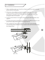
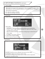
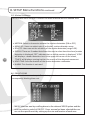
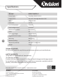
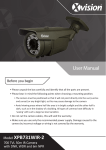
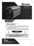
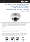
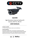
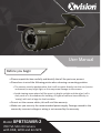
User Manual
Before you begin
• Please unpack the box carefully and identify that all the parts are present.
• Please bear in mind the following points when choosing a mounting position.
> The camera must be positioned so that it will not point directly into the sun (sunrise
and sunset) or any bright light, as this may cause damage to the camera
> Avoid viewing areas where half the area is in bright sunlight and the other half is
dark, such as in the shadow of a building. All types of cameras have difficulty in
‘seeing’ with such a large lux level variation.
• Do not cut the camera cables, this will void the warranty.
• Make sure you use only the recommended power supply. Damage caused to the
camera by incorrect voltage or wiring is not covered by the warranty.
Model: XPB731WIR-2
700 TVL 50m IR Camera
with DNR, WDR and 6m NPR
Contents
1. Safety Precautions ........................................................ 3
2. Product Description ...................................................... 4
3. Features ........................................................................ 4
4. Contents ....................................................................... 4
5. Installation .................................................................... 5
6. Camera OSD Control ..................................................... 7
2
7. OSD Menu Structure ..................................................... 7
8. SETUP Menu Functions ................................................. 9
8.1 Exposure .................................................................. 8
8.2 Colour ...................................................................... 8
8.3 Day/Night ................................................................ 9
8.4 Function .................................................................. 9
8.5 Motion Detection .................................................. 10
8.6 Privacy Mode ......................................................... 10
8.7 Camera Settings ..................................................... 11
8.8 System .................................................................... 11
8.9 Exit ......................................................................... 11
Thank you for purchasing this Xvision camera. Before operating this product, please
read this instruction manual carefully.
1. Safety Precautions
zz Do not disassemble or modify the camera. Please refer repairs or service to a
qualified service technician.
zz Take care when installing the camera. Avoid scratching the front glass window.
zz Avoid shock and vibration. Do not install the camera on an unstable surface. It
can be damaged by improper use or storage.
zz Do not attempt to point the camera at the sun or other extremely bright objects.
It can cause image smearing whether the camera is powered on or not and can
lead to the damage of the CCD (Charge Coupled Device).
zz When camera is installed next to equipment, such as wireless communication
device, that emits a strong electromagnetic field, some irregularity such as noise
on the monitor screen may occur.
zz Operating temperature: -10° ~ +45°C
zz Provide ample slack in the video and power cables once the camera is installed in
its final position.
zz Request the service of a qualified technician if the camera malfunctions or
generates excessive amounts of heat.
3
2. Product Description
The XPB731WIR-2 IR camera is designed for high risk applications, offering very high
resolution images of 700 TVL.
The camera feature high power Infrared (IR) LEDs offering 50m nightvision in
complete darkness and split glass technology that elimates any IR bounceback.
It features a powerful ARM based DSP, which processes the image in real time and
improves it by using Digital Noise Reduction and Wide Dynamic Range to produce an
even image, that does not suffer from bright or dark spots. Further enhancing the
picture is a megapixel lens, which is fully adjustable, allowing you to select the perfect
viewing angle for your application.
Additionally features such as an On Screen Display (OSD) with a Varifocal Lens that
allows the user to fully customise the camera’s settings to its environment. It is
designed for both internal or external use and can be wall/ceiling mounted.
3. Features
4
zz 700 TVL high resolution colour image
zz Sony 1/3” Ultra High Resolution CCD Sensor with an Xvision X7 DSP.
zz 2.8 to 12mm Varifocal Auto Iris Lens for 23 to 92° viewing angle for super sharp
images and easy selection of the optimum viewing angle during installation.
zz Integrated Long Life Infra Red LEDs turn on automatically in low light conditions
or complete darkness and provide up to 50 metres Night Vision.
zz Smart DNR (Digital Noise Reduction) reduces the noise on the image when
viewing in low lux environments (like at night). This reduces the size of the image
when being recorded by a DVR, resulting in a saving of disk space.
zz WDR (Wide Dynamic Range) feature allows the camera to display balanced
pictures even when the scene being watched has bright spots or various light
levels and back light conditions.
zz On Screen Display menu for complete customisation of the features.
zz Designed for wall mounting and is suitable for internal or external use.
4. Contents
•XPB731WIR-2 Camera
•User Manual
•Screws & Wall Plugs
•Allen Key
5. Installation
1. Select a suitable position on the wall or ceiling to install the camera and map
out the holes for the bracket.
2. Drill a hole in the middle of area on the wall or ceiling where the camera
is to be mounted, to allow the power and video cable to be fed through.
Alternatively, the cable can be surface mounted by taking the cabling out
through the side of the bracket.
3. Screw the bracket base to the wall or ceiling using the Wall Plugs and screws
supplied.
4. To change the bracket position during installation, the different screws on the
bracket can be adjusted as shown in the diagram (A-D).
5. Once installed the camera’s Zoom & Focus can be altered by adjusting
corresponding Focus and Zoom screws located underneath the camera body
(see image below) .
D
5
A
C
B
C
B
Zoom Focus
A
D
5. Installation continued
CONNECT THE POWER & VIDEO CABLES
1. Connect the video output to the monitor or other video device through a 75 Ohms
type coaxial cable.
2. Connect the power source, insert the AC plug into the AC socket and the DC plug
into the DC Jack (+12V DC in jack centre).
6. Camera OSD Control
6
Various camera settings can be adjusted using the OSD button located on the
camera’s cable.
Press the SET button to enter the OSD main menu, as shown below:
OSD Button Control Actions
UP
LEFT
SET
DOWN
RIGHT
Controls
For this Action
UP, DOWN
Select between items in a list
LEFT, RIGHT
Scroll through different menu options
SET (MENU)
Call up the OSD Menu/
Access a Menu Item
Please Note: If there is no activity on the OSD menu for a duration of 90 seconds the
main menu will disappear automatically from the screen.
7. OSD Menu Structure
EXPOSURE
COLOUR
DAY/NIGHT
FUNCTION
MOTION DETECTION
PRIVACY ZONE
CAMERA SETTINGS
SYSTEM
EXIT
Please Note:
• At the bottom of each menu item there is the option of ‘EXIT’. Once the user has
changed the required settings within the menu option, selecting the ‘EXIT’ option
will give the following options:
-- SAVE: This option will save any changes and will then return to the main menu.
-- RETURN: This option allows the user to return to the main menu WITHOUT
saving any changes.
-- EXIT: This option exits the user from the menu structure WITHOUT saving any
changes.
•The arrow symbol on the OSD menu
indicates that there is are additional
options available. You can select the various options by using the LEFT/RIGHT
controls.
7
8. SETUP Menu Functions
8.1. EXPOSURE This option allows the user to alter the camera’s lens settings. The following options
are available:
8
•LENS: Users can either select DC or ELC.
•HBLC/D-WDR: There are 4 background light functions to choose from
-- BLC (Backlight Compensation): The BLC function makes objects in front of
a bright scene (such as a window on a bright sunny day) clearer to see by
increasing their brightness and making the background darker.
-- HLI (Highlight Supression): Select this feature to select masking of bright areas
in the image, such as when viewing number plates when car headlights are on.
-- D-WDR (Wide Dynamic Range - feature allows the camera to display balanced
pictures even when the scene being watched has bright spots or various light
levels and back light conditions).
-- OFF : Turns off all the fucntions.
•AGC (Auto Gain Control): feature allows the camera to display balanced pictures
even when the scene being watched has bright spots or various light levels and
back light conditions.
•3D-DNR (Digital Noise Reduction): This function reduces the noise on the image
when viewing in low lux environments (like at night). This reduces the size of the
image when being recorded by a DVR, resulting in a saving of disk space.
•SENSE-UP: Improves the image in very low light conditons. The options include
image being amplified from a range of x2 to x512, AUTO and OFF.
8.2. Colour (RGB)
This option allows the user to alter the camera’s colour settings. The following
options are available:
8. SETUP Menu Functions continued
8.2. Colour (RGB)
Continued
•WB MODE (White Balance) - It is used to restore the authenticity of the color,
affected by the change of color temperature. Users can select the options: Auto
White Balance / Auto-tracking White Balance / Lock White Balance / Manual
White Balance respectively.
•R-Y: adjust the red gain manually.
•B-Y: adjust the blue gain manually.
8.3. Day/Night Configure the camera day/night function:
•D&N MODE
-- AUTOMATIC: The camera automatically switches over to nightvision
-- COLOR: A colour image is always displayed with nightvision mode being
switched off permanently.
-- B/W: The camera remains in nightvision mode giving a constant black and
white image
-- EXTERNAL: This mode is not used
•C_SUP: Colour Supress setting.
•A_SUP: Aperature Supress settings.
8.4. Function
Configure the camera’s image features with the following options:
•MIRROR: Provides a mirror reflection (horizontal) of the image.
•SHARPNESS: Adjusts the sharpness of the image.
•LSC (Peripheral Brightness Compensation): If you need to compensate
brightness, set switch as ON.
9
8. SETUP Menu Functions continued
8.5. Motion Dectection This function alerts the user if motion has been detected within a defined area:
10
•MOTION: Select to choose to activate the motion dectection (ON or OFF)
•AREAS SEL: Users can select upto 4 individual motion detection areas.
•SENSTITI: Users can set the senstivity of the motion detection (range 0-30).
•DISPLAY: There are 3 modes that allows the user to select how the alarm/motion
detection is displayed; ’OFF’ indicates that no visible reaction is displayed, ‘ICON’
will display a motion detection icon in the upper-left corner of the screen,
‘TRACK’ will display a moving track on the screen of the detected movement.
•HOLD TIME: Sets the duration of the motion detection notification.
•ALARM: This function is not used.
8.6. PRIVACY ZONE Privacy function can create up to 8 masks to protect sensitive areas in the scene and
consequently blocking them out.
• MASK: Select an area by scrolling down to the relevant ‘MASK’ option and the
user can select to switch it ON/OFF. Once an area has been selected the user
can set the specific mask by setting up the size and location of each area.
8. SETUP Menu Functions continued
8.7. CAMERA SETTINGS
This function allows the user to add on-screen viewing options:
•TITLE DISP: Allows the user to set a custom title to be displayed on the screen.
•MANUAL DPC (Dead Pixel Compensation): Manual process dead pixels on the
screen.
•AUTO DPC: When AUTO is used, the camera will remove defective pixels from an
image automatically.
•OLPF: This function is not used.
•MONITOR: Users can optimise the image for LCD or CRT monitors.
•GAMMA: Allows the user to adjust the gamma value of the image.
8.8. SYSTEM
This function allows the user various system settings:
•CAMERA ID: This function is not used on this camera.
•COMMUNICATION: This function is not used on this camera.
•LANGUAGE: Allows the user to set the language for the OSD menu.
8.7. CAMERA SETTINGS
This function displays the various exit options:
•FACTORY SET: This option will restore the camera to its orginal factory settings.
•SAVE & EXIT: This option allows the user to save any changed settings and exit
the menu options completely.
•EXIT: This option exits the user from the menu WITHOUT saving any changes.
11
Specifications
12
Model:
XPB731WIR-2
Picture Type:
Day/Night (B/W & Colour)
Image Sensor:
Sony 1/3” Ultra High Resolution CCD
DSP:
Xvision X7 DSP
Resolution:
700 TVL
Lens Viewing Angle:
23 to 92°
Infra Red Night Vision:
50 metres
Minimum Illumination:
0 Lux (IR on)
Audio:
No
Operating Voltage:
12V DC 700mA
Suggested Power Supply:
12V DC 1250mA
Mounting:
Wall/Ceiling
Weatherproofing:
Yes
Dimensions (WxHxD):
101.3 x 97.3 x 298.2 mm
Weight:
1.1 Kg
TECHNICAL SUPPORT:
For Technical Support for any Xvision product please contact your local distributor.
LIMITED WARRANTY:
This product is supplied with a 1 Year warranty.
The Warranty excludes:
Products that have been misused, (including accidental damage) and damage caused
by normal wear and tear. In the unlikely event that you encounter a problem with this
product, it should be returned to the place of purchase.
Manufactured exclusively for Xvision - www.xvision.com
Head Office
Xvision Group (UK)
Unit 2, Valley Point, Beddington Farm Road,
Croydon, Surrey CR0 4WP
E: [email protected]
Far East Office
Kyoung Am Building,
157-27 Samsung-dong
Kangnam-ku, 135 090 Seoul, Korea
E: [email protected]