1
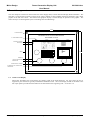
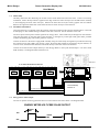
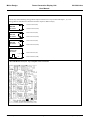
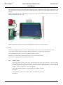
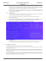
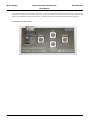
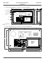
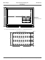
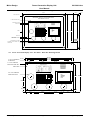
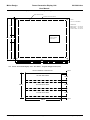
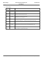
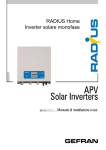
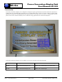
Micha www.micha.co.uk Power Generation Display Unit User Manual 801309 1. Introduction The Power Generation Display Unit is designed to display the power generated by any Power Generation system but is usually used on a renewable energy generation site, e.g. Photovoltaic (PV) or Wind. For a PV system, PV panels would typically be installed on a building and provide power directly to the mains grid via inverters. Energy meters provide pulses to the Power Generation Display Unit to enable the energy generated to be counted and displayed. The Power Generation Display Unit is available in two sizes as described in the following table: Micha Part Number Description Graphic Size 101 820 Power Generation Display Unit 420mm wide x 300mm high (A3 Graphic Size) 101 640 Power Generation Display Unit 600mm wide x 500mm high MF/11th April 2013/Issue 8 Page 1 of 12 The Micha Design Company Ltd Micha Design Power Generation Display Unit User Manual 801309-8.doc 2. General Arrangement The unit comprises a back-box which houses the Power Supply PCB, Control PCB and Display PCB Assemblies. The back-box is covered with two sheets of clear acrylic (420 x 300mm or 600 x 500mm) which are designed to trap a fixed graphic of the end users choice. The backlit LCD graphics display is visible through an aperture in the graphic. The sheets of acrylic are held together by the surrounding bezel and M8 fixings. 605mm 4 x M8 DOME NUTS REAR PERSPEX - WITH CUT-OUT FOR LCD GRAPHICS DISPLAY FRONT PERSPEX - NO CUT-OUT 8 x M16 BLANKING PLUGS 4 x BACK BOX FIXINGS POWER SUPPLY PCB EARTH STUD POWER GENERATION DISPLAY UNIT PCB ASSEMBLY MDC 401 221 TB1 R1 TB2 TB3 0V +5V TB4 0V +5V LED1 EARTH POWER NEUTRAL LIVE 2 D3 R20 R21 R23 1 3 TP6 2 D4 R25 R26 R22 1 LED4 C6 XTAL1 3 IC6 TP7 RN3 UP C12 IC8 SW6 SET TR4 LCD RED +VE BACK LIGHT WHT -VE C4 C8 + C9 C10 C11 IC7 TESTED R8 RN2 SERIAL NO. 3 IC5 SW4 COUNTRY OF ORIGI N: U. K.Micha 2 D2 R18 R19 R16 1 LED3 C13 R17 3 TP5 R3 R5 J1 R13 R14 D1 R11 R12 R15 2 LED2 RN4 IC4 R2 R4 RN1 C14 C7 SW3 TR3 TB5 TP4 IC2 IC9 LED1 IC3 SW2 TR2 TB4 C3 LED5 R10 POWER SW1 TR1 TB3 + TP2 0V 1 SP NO COM SP NO COM SP NO COM SP NO COM INPUT 2 INPUT 3 INPUT 4 IN PUT 1 BEZEL TB2 TESTED R24 +5V POWER SERIAL NO. PROGRAM PORT J4 MENU J2 CONTRAST LCD GRAPHICS DISPLAY PCB 505mm SW7 SW8 SW9 RUN PN: 401195 ISSUE J3 POWER GENERATION CONTROL PCB ASSEMBLY 1 R6 TB6 C2 TP1 R27 TB1 PSU1 VR1 F1 SW10 SELECT DOWN CONTROL PCB BACK BOX 4 HOLES FOR POSSIBLE CABLE ENTRY 8 x REAR ACRYLIC FIXINGS EXTERNAL SET-UP CONTROL UNIT CONNECTOR 2.1. NOTE: LCD Display When fully assembled, the LCD Display sits slightly proud of the metal back-box. For this reason the unit is supplied in parts which are typically assembled at installation time. The LCD Display should not be fitted to the four nylon pillars provided until the back-box has been fitted to the supporting wall – see section 3.4 MF/11th April 2013/Issue 8 Page 2 of 12 The Micha Design Company Ltd Micha Design Power Generation Display Unit User Manual 801309-8.doc 3. Installation 3.1. Disassembly Carefully remove the four M8 fixings in the four corners of the bezel and remove the bezel.. If this is an existing installation, remove the tape which is applied to the edge of the two sheets of acrylic (this should be done carefully to avoid dropping the front sheet of acrylic). Remove the front sheet of acrylic and any graphic that is installed. Remove the eight M4 countersunk screws that hold the rear sheet of acrylic to the back box. 3.2. Installation of Back Box Using the back box as a template, mark the position of the four mounting holes onto the desired location. Drill and fit rawl plugs or other suitable fixings to hold the back box to the wall. Fix the back box to the wall. The unit requires mains power and the signal for the energy meter. These cables may be brought into the enclosure using the large holes on the back wall of the enclosure, or through any of the eight cable gland holes provided (remove the blanking plug and fit M16 glands as required). Connect the mains to the Power Supply PCB Assembly using the cable clamp arrangement provided and ensuring the connections are tight. Note: with Version 1 PSU, the Earth cable should be connected to the pcb terminal, on Version 2 PSU, the Earth cable should be connected directly to the earth stud on the back-box. Connect the Volt-Free Pulse Output from up to four Energy Meters to the inputs marked Input 1-4 on the Control PCB Assembly. See diagram below and Section 3.4. PSU Ver.2 UP TO 4 ENERGY METERS MAY BE CONNECTED POWER SUPPLY PCB POWER GENERATION DISPLAY UNIT PCB ASSEMBLY MDC 401 221 TB1 R1 LED1 EARTH ENERGY METER 4 ENERGY METER 3 ENERGY METER 2 ENERGY METER 1 MAINS CABLE POWER TB2 TB3 0V +5V TB4 0V +5V NEUTRAL LIVE F1 PSU1 SERIAL NO. PSU Ver.1 TESTED VOLT-FREE PULSE OUTPUT VOLT-FREE PULSE OUTPUT Control PCB Assembly See Section 3.4 VOLT-FREE PULSE OUTPUT VOLT-FREE PULSE OUTPUT 3.3. Energy Meter Pulse Output The Unit is capable of sensing pulses that have an on and off time of at least 100ms. See diagram below. ENERGY METER VOLT-FREE PULSE OUTPUT 100mS MIN ON 100mS MIN OFF MF/11th April 2013/Issue 8 Page 3 of 12 The Micha Design Company Ltd Micha Design Power Generation Display Unit User Manual 801309-8.doc 3.4. Control Printed Circuit Board (PCB) Control PCB Issue 4: Connect any of the following Energy Meter Output Connections to any Control PCB Input 1, 2, 3 or 4: (Energy Meters manufacturers mark the SO Pulse output in different ways) ENERGY METER OUTPUT Connect to Terminal 2 (NO) ENERGY METER OUTPUT Connect to Terminal 2 (NO) ENERGY METER OUTPUT Connect to Terminal 2 (NO) Connect to Terminal 3 (COM) Connect to Terminal 3 (COM) Connect to Terminal 3 (COM) SWITCHED POSITIVE OUTPUT Connect to Terminal 1 (SP) 5-12V 0V Connect to Terminal 3 (COM) Control PCB Issue 4 Layout: Up to 4 inputs can be connected MF/11th April 2013/Issue 8 Page 4 of 12 The Micha Design Company Ltd Micha Design Power Generation Display Unit User Manual 801309-8.doc 3.5. LCD Display Installation After the back-box has been securely fitted to the supporting wall, unpack and carefully fit the LCD Display to the four nylon pillars using a pozi-screw and nylon washer (provided) on each corner of the LCD Display (do not overtighten). Plug the ribbon cable into the corresponding connector (J2) on the Control PCB and plug the back-light connector into its corresponding connector (J1). Remove the protective plastic covering the LCD Display at this point (3 or 4 strips of plastic). 3.6. Set up At this point, apply mains power to the unit. Set the Set/Run switch on the Control PCB Assembly to SET. Use the Menu switch to advance through the following parameters in sequence (see photo below): When a parameter is flashing, use the Up and Down switches to adjust. When the unit is set to RUN, all parameters will be stored in non-volatile memory. See section 3.8 regarding the External Set-up Control Unit. 3.6.1. Set Pulse Value The Energy Meters produce pulses which represent Watt-hours (Wh) being generated. The unit needs to be programmed to set the Pulse Value in Wh. Also, if a number of identical systems are in place but only one of the systems has energy meters fitted, then the Pulse Value can be multiplied by 1 to 40 to enable the display to show the energy for the entire arrangement. First set the number of systems (1 to 40) using the Up and Down switches. Press Menu. Now set the Pulse Value (1Wh, 10Wh, 100Wh, 1kWh, 10kWh per pulse). Press Menu. MF/11th April 2013/Issue 8 Page 5 of 12 The Micha Design Company Ltd Micha Design 3.6.2. Power Generation Display Unit User Manual 801309-8.doc Set Instant Power Time The instantaneous power being generated is calculated by counting the number of pulses received over a period of time. This parameter should be set for a time that allows a number of pulses to be received (which depends on the size of the system and the pulses sent out by the energy meter). The Instant Power Time interval can be set to 1, 2, 3, 5, 10, 12, 15, 20, 30 and 60 minutes. The instantaneous power generated will appear on the display after the time selected and then remain unchanged until the next update. 3.6.3. Set Total Energy If a display unit is being installed after the system is up and running or as a replacement, it may be desired to enter the energy in Watt-hours (Wh) that has already been generated. The installer may set the Total Energy as any 10-digit number representing Total Energy in Wh. How to set Total Energy: When any digit of this parameter is flashing, use the Up and Down switches to change the digit. Use the Menu switch to advance through all the digits. (The example below shows how to set 1234kWh) Important: Press the SELECT switch to update the Set Total Energy figure. 3.6.4. Testing the unit Each of the Pulse Inputs has a test switch associated with the input terminal connector. By pressing the test switches the installer may simulate pulses being received and see the results on the display. 3.7. Installation of Acrylic Sheets Using the eight M4 countersunk screws, fix the rear sheet of acrylic to the back box. Place the graphic and the front sheet of acrylic onto the rear sheet of acrylic and temporarily fix them together using the top two M8 fixings. Apply clear self-adhesive tape all the way round the edges of the two acrylic sheets to seal the two together. This is important as it can prevent small insects or moisture getting between the two sheets and affecting the appearance of the graphic and display. Using the four M8 fixings, fix the bezel in place (note that the front sheet will only be held in place by the adhesive tape if the top two fixings are removed and the sheet is not supported). The four M8 fixings should be inserted from the rear and the dome top nut used to secure the front. MF/11th April 2013/Issue 8 Page 6 of 12 The Micha Design Company Ltd Micha Design Power Generation Display Unit User Manual 801309-8.doc 3.8. External Set-up Control Unit Units produced after June 2010 have the facility to connect an External Set-up Control Unit via a 9-way D-type connector on the bottom side surface of the unit. The External Set-up Control Unit has the same switches as the Main Control PCB and works in the same way. It allows changes to be made without disassembling the unit. External Set-up Control Unit: MF/11th April 2013/Issue 8 Page 7 of 12 The Micha Design Company Ltd Micha Design Power Generation Display Unit User Manual 801309-8.doc 4. Drawings 4.1. Power Generation Display Unit - 42 x 30cm (A3) – General Arrangement 426mm 70mm 12 4 x M6 DOME NUTS 6 x REAR ACRYLIC FIXINGS REAR PERSPEX - WITH CUT-OUT FOR LCD GRAPHICS DISPLAY EARTH STUD 4 x BACK BOX FIXINGS FRONT PERSPEX - NO CUT-OUT POWER GENERATION DISPLAY UNIT PCB ASSEMBLY MDC 401 221 TB1 R1 TB2 TB3 0V +5V TB4 0V +5V LED1 EARTH 1 HOLE FOR POSSIBLE CABLE ENTRY POWER NEUTRAL LIVE F1 PSU1 SERIAL NO. TESTED POWER SUPPLY PCB 2 D3 R2 0 R2 1 R2 3 1 3 1 2 D4 R2 5 R2 6 R2 2 LED4 C6 C4 C8 LCD GRAPHICS DISPLAY PCB + XTAL1 R2 4 COU NTR Y OF ORI GIN : U.K. Micha 3 SW4 C10 C11 IC7 1 J2 CONTRAST RN3 UP C12 IC8 R2 7 2 D2 R1 8 R1 9 R1 6 1 LED3 TP6 IC5 TR3 RN2 C9 SERIAL NO. 3 SW3 TB5 C13 LCD RED +VE BACK LIGHT WHT -VE TESTED R1 4 R1 3 2 TP5 IC4 TR2 RN1 C7 LED2 RN4 SW6 250mm R3 R5 J1 C14 SW2 TB4 R2 R4 IC9 LED1 TP4 IC3 TR1 TB3 IC2 R8 LED5 R10 D1 R1 1 R1 2 R1 5 1 MENU SW7 SW8 SET 3 SP NO COM SP NO COM SP NO COM SP NO COM INPUT 1 INPUT 4 INPUT 3 INPUT 2 BACK BOX TB2 303mm PROGRAM PORT J4 C3 + TP2 POWER SW1 R6 TB6 C2 TP1 0V VR1 TB1 +5V POWER R1 7 BEZEL SW9 IC6 TR4 TP7 RUN PN: 401195 ISSUE POWER GENERATION CONTROL PCB ASSEMBLY SW10 J3 SELECT DOWN CONTROL PCB 4 x M16 BLANKING PLUGS EXTERNAL SET-UP CONTROL UNIT CONNECTOR 15 4.2. Power Generation Display Unit - 42 x 30cm (A3) – Back Box Mounting Details POWER GENERATION DISPLAY UNIT PCB ASSEMBLY MDC 401 221 TB1 R1 LED1 EARTH POWER TB2 TB3 0V +5V TB4 0V +5V NEUTRAL LIVE F1 PSU1 SERIAL NO. TESTED POWER SUPPLY PCB PROGRAM PORT J4 C6 C14 C7 3 TP5 2 D3 R20 R21 R23 1 SW3 3 TR3 LED3 IC5 TP6 1 SW4 LED4 2 D4 R25 R26 R22 TB5 3 TR4 IC6 RN2 C9 R17 D2 R18 R19 R16 2 TR2 IC4 C13 Micha 1 LED2 RN4 C10 XTAL1 C11 IC7 R24 3 TP4 R3 R5 J1 RN1 TESTED D1 R11 R12 R15 2 IC3 R2 R4 IC9 LED1 SW2 TB3 IC2 RN3 UP C12 IC8 SW6 LCD RED +VE BACK LIGHT WHT -VE C4 C8 MENU 1 J2 CONTRAST VR1 C3 R27 1 SP NO COM SP NO COM SP NO COM SP NO COM INPUT 1 INPUT 4 INPUT 3 INPUT 2 TR1 + LED5 R10 POWER SW1 TB2 TB4 C2 + TP2 SERIAL NO. TP1 0V R8 TB6 +5V R13 R14 TB1 POWER COUNTRY OF ORIGIN: U.K. 250mm R6 180mm SW7 SW8 SET SW9 TP7 RUN PN: 401195 ISSUE J3 POWER GENERATION CONTROL PCB ASSEMBLY LCD GRAPHICS DISPLAY PCB SW10 SELECT DOWN CONTROL PCB 330mm 370mm MF/11th April 2013/Issue 8 Page 8 of 12 The Micha Design Company Ltd Micha Design Power Generation Display Unit User Manual 801309-8.doc 4.3. Power Generation Display Unit - 42 x 30cm (A3) – Graphic Design Detail (Overall) 13mm 8mm A A 134.0 mm 227.0 mm 303mm 120.0 mm 261mm SEE DRAWING 501647 FOR DISPLAY DETAIL. 1st LINE TEXT AREA 2nd LINE TEXT AREA ACRYLIC SHEET IS 422MM X 299MM 90.0 mm 3rd LINE TEXT AREA 8mm A A 13mm 13 8 384mm 8 13 426mm 4.4. Power Generation Display Unit - 42 x 30cm (A3) – Graphic Design Detail (Text) HOLE IN GRAPHIC FOR DISPLAY 1st LINE TEXT AREA 3mm 23mm 6mm 90mm 2nd LINE TEXT AREA 23mm 6mm 3rd LINE TEXT AREA 120mm MF/11th April 2013/Issue 8 Page 9 of 12 23mm 6mm The Micha Design Company Ltd Micha Design Power Generation Display Unit User Manual 801309-8.doc 4.5. Power Generation Display Unit - 60 x 50cm – General Arrangement 605mm 73mm 15mm 4 x M8 DOME NUTS REAR PERSPEX - WITH CUT-OUT FOR LCD GRAPHICS DISPLAY FRONT PERSPEX - NO CUT-OUT 8 x M16 BLANKING PLUGS 4 x BACK BOX FIXINGS POWER SUPPLY PCB EARTH STUD POWE R GENERAT ION DIS PLA Y UNIT PCB ASSEMBLY MDC 401 221 TB1 R1 TB2 TB3 0V +5V TB4 0V +5V LED1 EARTH POWER NEUTRAL LIVE 1 D3 R20 R21 R23 2 3 IC5 TR3 1 SW4 TB5 Mi cha 3 LED3 TP6 XTAL1 LED4 2 D4 R25 R26 R22 C9 C10 COUNTRY OF ORIGIN: U.K. 2 D2 R18 R19 R16 1 TP5 SW3 C13 C11 IC7 C12 IC8 LCD GRAPHICS DISPLAY PCB C4 1 J2 CONTRAST UP SW6 505mm 300mm SW7 MENU SW8 SW9 SET 3 IC6 TR4 RN3 LCD RED +VE BACK LIGHT WHT -VE C8 + RN2 SERIAL NO. C7 TEST ED R8 C6 3 IC4 TR2 TB4 RN1 C14 LED2 RN4 R3 R5 J1 R14 R13 D1 R11 R12 R15 2 NO COM SP NO COM SP NO COM SP NO COM INPUT 1 INPUT 4 INPUT 3 INPUT 2 TP4 R2 R4 IC9 LED1 IC3 SW2 R17 1 SP TB3 LED5 R10 POWER SW1 TR1 R24 0V TB2 TEST ED IC2 R27 POWER SERIAL NO. PROGRAM PORT J4 C3 + TP2 R6 +5V BEZEL PSU1 TB6 C2 TP1 VR1 F1 TB1 TP7 RUN PN: 401195 ISSUE J3 POW ER GENERATION CONTROL PCB ASSEMBLY SW10 SELECT DOWN CONTROL PCB BACK BOX 4 HOLES FOR POSSIBLE CABLE ENTRY 8 x REAR ACRYLIC FIXINGS EXTERNAL SET-UP CONTROL UNIT CONNECTOR 15mm 4.6. Power Generation Display Unit - 60 x 50cm – Back Box Mounting Details 450.0 mm 420.0 mm 120.0 mm 15.0mm 8 x 16.0 mm DIAMETER GLAND HOLE 120.0 mm 4 x 5.0 mm DIAMETER BACK BOX FIXING HOLE 120.0mm POWER SUPPLY PCB POWER GENERATION DISPLAY UNIT PCB ASSEMBLY MDC 401 221 EARTH STUD TB1 R1 TB2 TB3 0V +5V TB4 0V +5V LED1 EARTH POWER NEUTRAL LIVE F1 4 x 61.5 mm DIAMETER CABLE ENTRY HOLE TB1 PSU1 TB6 C2 TP1 +5V + SERIAL NO. TESTED PROGRAM PORT J4 C3 IC2 R2 R3 R4 2 3 TP6 1 2 D4 R2 5 R2 6 R2 2 LED4 C6 C8 + C9 C10 XTAL1 C11 IC7 RN3 UP C12 IC8 SW6 MENU 1 J2 250.0mm 300.0 mm CONTRAST SW7 SW8 3 SET TR4 TESTED R1 3 R1 4 RN2 SERIAL NO. D3 R2 0 R2 1 R2 3 1 LED3 IC5 SW4 LCD GRAPHICS DISPLAY PCB C4 R6 3 TP5 LCD RED +VE BACK LIGHT WHT -VE VR1 2 D2 R1 8 R1 9 R1 6 1 LED2 RN4 IC4 C13 R1 7 3 C7 SW3 TR3 TB5 C14 SW2 TR2 TB4 TP4 RN1 R2 4 D1 R1 1 R1 2 R1 5 2 IC3 R5 J1 IC9 LED1 TR1 TB3 LED5 R10 R2 7 POWER SW1 R8 TP2 0V 1 SP NO COM SP NO COM SP NO COM SP NO COM INPUT 1 INPUT 4 INPUT 3 INPUT 2 100.0 mm TB2 COUN TRY OF ORIGIN: U. K. Micha POWER SW9 IC6 TP7 RUN PN: 401195 ISSUE POWER GENERATION CONTROL PCB ASSEMBLY SW10 J3 SELECT DOWN CONTROL PCB 50.0mm 25.0mm 52.5mm MF/11th April 2013/Issue 8 32.5 140.0mm Page 10 of 12 140.0 mm The Micha Design Company Ltd Micha Design Power Generation Display Unit User Manual 801309-8.doc 4.7. Power Generation Display Unit - 60 x 50cm – Graphic Design Details BEZEL INNER OUTLINE OUTLINE OF ACRYLIC SHEETS 16 mm HOLES: 4 OFF 9.0 mm DIAMETER DIMENSIONS: 205mm 500 mm 90mm BEZEL OUTER: 505 x 605 mm BEZEL INNER: 445 x 545 mm ACRYLIC SHEET: 500 x 600 mm HOLE IN GRAPHIC FOR DISPLAY 468mm 205mm 16 mm 16 568mm 374 mm 16 120 mm 106mm 600mm 4.8. Power Generation Display Unit - 60 x 50cm – Graphic Design Detail (Text) HOLE IN GRAPHIC FOR DISPLAY 1st LINE TEXT AREA 3mm 23mm 6mm 90mm 2nd LINE TEXT AREA 23mm 6mm 3rd LINE TEXT AREA 120mm MF/11th April 2013/Issue 8 Page 11 of 12 23mm 6mm The Micha Design Company Ltd Micha Design Power Generation Display Unit User Manual 801309-8.doc 5. Software 5.1. Software History Software Version Date Released Comments 801 264 22nd Aug 2006 First Production Software 23rd Aug 2007 Change CO2 factor from 0.43 to 0.568 9th Nov 2007 Modifications to Settings Screen Layout Ver 1.0 801 264 Ver 1.1 801 264 Ver 1.2 801 264 Refresh screen every 5 seconds 19th Nov 2007 Ver 1.3 801 264 Settings Screen: Pulse Value now adjustable from 1-9 units (For multiple building use – assuming all units producing same power) 24th June 2008 Default for Instant Power Update Time changed to 2 minutes 1st Oct 2009 Settings Screen: Pulse Value Units can now be adjusted from 1-40 11th April 2013 Added new Line 4 on Settings Menu as a reminder to the user Ver 1.4 801 264 Ver 1.5 801 264 Ver 1.6 “(Press SELECT to update Total Energy)” MF/11th April 2013/Issue 8 Page 12 of 12 The Micha Design Company Ltd