1
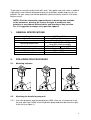
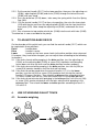
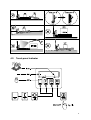
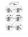
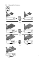
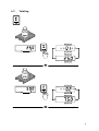
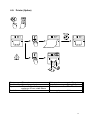
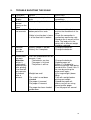
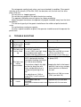
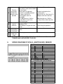
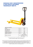
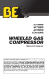
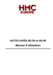
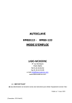
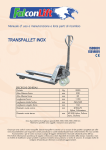
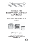
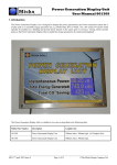
User Manual HP ESR20
Note: Operator MUST read and understand these operating instructions before
using this Hand Pallet truck.
0
OPERATIONAL MANUAL
Index
1.
2.
3.
4.
5.
6.
7.
8.
9.
General specifications
Pre-operation procedure
2.1. Mounting indicator
2.2. Attaching the handle to pump unit
To adjust release device
Use of weighing pallet truck
4.1. Accurate weighing
4.2. Touch panel indicator
4.3. 1. Net + 2. Tare = 3. Gross
4.4. On / Off
4.5. Error messages
4.6. Zero and tare functions
4.7. Total and reset
4.8. Totalling
4.9. Printer (Option)
4.10. Printout (Option)
4.11. Paper change (Option)
Trouble shooting the scale
Maintenance
6.1. Oil
6.2. To remove air from the pump
6.3. Daily check and maintenance
6.4. Lubrication
6.5. Battery replacement
6.6. Maintenance of display unit
Guide to safe operation
Trouble shooting
Wiring diagram of scale, junction box, sensor
2
2
2
2
3
3
3
4
5
5
6
8
9
10
11
12
13
14
15
15
15
15
15
15
15
15
16
17
Rev.17.07.07
1
Thank you for using this pallet truck with scale. Your pallet truck with scale is made of
high quality steel and was designed to give you a durable, reliable and easy to use
product. For your safety and correct operation, please carefully read this instruction
before using it.
NOTE: All of the information reported herein is based on data available
at the moment of printing. We reserve the right to modify our own
products at any moment without notice and incurring in any sanction.
So, it is suggested to always verify possible updates.
1.
GENERAL SPECIFICATIONS
Capacity
Power Source
Environment
Operating temperature
Min/Max fork height
Features weighing accuracy
Width over forks
Fork Length
2,000kg/4,500lbs
4 “AA” penlight batteries
General purpose, dry
-10oC to 40oC (14oF to 104oF) with
10 to 95% relative humidity
76mm/190mm
88mm/200mm
+1.0kg for loading 2,000kg
568mm/703mm
1150mm/1220mm
2.
PRE-OPERATION PROCEDURE
2.1.
Mounting indicator
2.2.
Attaching the handle to pump unit
2.2.1. Insert the draw-bar onto the pump piston (303), then use a hammer to insert
the axle with hole (G105) into the hydraulic pump and draw bar from the right
to the left (see figure 1).
2
2.2.2. Put the control handle (G117) to the lower position, then pass the adjusting nut
(G104), adjusting bolt (G103) and chain (G102) through the hole of the axle
(G105) with your hand.
2.2.3. Press the draw-bar (G110) down, take away the spring which fixes the Spring
Cap (301).
2.2.4. Put the control handle (G117) to then raise position, the raise the lever plate
(319) with the pin and insert the adjusting bolt (G103) into the front slot of the
lever plate (319). Note: keep the adjusting nut (G104) underneath the lever
plate.
2.2.5. Use a hammer to tap another elastic pin (G106) into the axle with hole (G105)
The draw-bar is now assembled to the pump.
3.
TO ADJUST RELEASE DEVICE
On the draw-bar of this pallet truck, you can find the control handle (G117) which can
be regulated in three positions:
Raise
- handle down
Drive
- handle in center
Lower
- handle up, the lever moves back to the drive position when released.
If, however, they have been changed, you can adjust them according to the following
instructions:
3.1. If the forks elevate while pumping in the drive position, turn the adjusting nut
(G104) on the adjusting bolt (G103) or screw (318) clockwise until pumping
action does not raise the forks and the drive position functions properly.
3.2. If the forks descend while pumping in the drive position, turn the nut(104) or
screw(318) counter-clockwise until the forks do not lower.
3.3. If the forks do not descend when the control handle (117) is in the lower
position, turn the nut(104) or screw (318) clockwise until raising the control
handle(117) lowers the forks. Then check the drive position according to item
3.1 and 3.2 to be sure the nut (104) and screw(318) is in the proper position.
3.4. If the forks do not elevate while pumping in the raise position, turn the nut (104)
or screw (318) counter-clockwise until the forks elevate while pumping in the
raise position. Then check the lower and drive position according to item 3.1,
3.2 and 3.3.
4.
USE OF WEIGHING PALLET TRUCK
4.1. Accurate weighing
3
-2°
4.2. Touch panel indicator
4
4.3. 1. Net + 2. Tare
= 3. Gross
4.4. On / Off
5
4.5.
Error messages
6
7
4.6.
Zero and tare functions
8
4.7.
Totalling
9
4.8.
Total and reset
10
4.9. Printer (Option)
Printer
:Thermal
Functionality :Manual paper feed
Paper
:Thermal roll, roll diameter
maximum 32 mm, width 58mm
Resolution
:203 DPI
Print speed
:up to 45 mm/sec.
Temperature range :0 tot +40°C
Dimensions
:77 x 77 x 44 mm
Power supply
:6 Vdc
11
4.10. Printout (Option)
12
4.11. Paper change (Option)
13
5.
TROUBLE SHOOTING THE SCALE
NO TROUBLE
1
HELP1 in the
display
2
Text is not
printed
clearly on the
ticket
3
The scale is
not accurate
CAUSE
-The load is too big for the
scale
-Battery voltage is too low
SHOOTING
-Remove the load
immediately.
-Change the batteries.
-The fork shoe is touching the
bottom part of the scale
-Remove anything that
restricts the movement of the
scale.
-Check the connection in
junction box confirming safe.
-Stand on the 4 corners of the
scale. The load cell in the
corner with a different weight
should be replaced.
-Change the batteries.
-Change the batteries.
-Cable in junction box is loose
-1 of the load cells is broken
4
Indicator
can’t be
turned on.
-Battery voltage is too low.
-Battery life is complete.
5
Printer does
not work
Attention,
printer is
switched off
automatically
after printing.
Line feed will
only operate
3 seconds
after a
printout.
-The LED should be on for 30
seconds. If not:
-The batteries are low.
-The paper is finished
-The printer is off line
-Weight too small
-The scale has not been
unloaded
-The paper is jammed
-The paper is incorrect
-The paper has been loaded
upside down
-Change the batteries
-Replace paper roll
-Button 1 is disabled to
prevent the printer from being
turned off-line. Check if this is
the case by pushing the
button once again
-Lift a large weight (above
20kg).
-Take off a weight before
printing next weight
-Reload the paper roll.
-Make sure you are using
thermal printer paper.
-Turn the paper roll around.
14
6.
MAINTENANCE
The pallet truck is largely maintenance free.
6.1. Oil
Please check the oil level every six months. The oil can be hydraulic oil: ISO VG32,
its viscosity should be 30cSt at 400 C, total volume is about 0.4lt.
6.2. To remove air from the pump
Air may come into the hydraulic oil during transportation or if the pump has been
turned upside down. It can cause the forks not to elevate while pumping in the raise
position. The air can been removed in the following way: put the control handle (117)
to the lower position, then move the draw-bar up and down several times.
6.3. Daily check and maintenance
Daily check of the pallet truck with scale can limit wear as much as possible. Special
attention should be paid to the wheels, the axles, as thread, rags, etc. may block the
wheels. The forks should be unloaded and lowered in the lowest position when the
job is over.
6.4. Lubrication
All bearings and shafts are provided with long-life grease at the factory. You only
need add long-life grease at monthly intervals or after each time the lubrication points
of the truck are cleaned thoroughly.
6.5. Battery replacement
A) Remove the screw (238-7) and the battery cover (238-8).
B) Use 4 new “AA” batteries (238-9) to replace the old ones.
C) Replace the battery cover (238-8) and tighten the screw (238-7) securely.
6.6. Maintenance of display unit
The weighing system meets up to the protection class IP65. This means that dust
or moisture (rain or water beam from all sides), will not influence the operation of
the electronics. However, high-pressure cleansing in combination with warm water
or chemical cleansers will lead to the entry of moisture and therefore negatively
influence the operation of the system.
7.
GUIDE TO SAFE OPERATION
To pull the truck, always move the control handle into the drive position. This
makes the draw-bar easier to move and depressurizes the pump section of the
hydraulics. This preserves the hydraulic seals and the valve components. A long
service life can be expected.
Operator should read all warning signs and instructions here and on the pallet
truck before using this truck with scale.
Do not operate a pallet truck with scale unless you are familiar with it and have
been trained or authorized to do so.
15
Do not operate a pallet truck unless you have checked its condition. Give special
attention to the wheels (227or 234, 310), the draw-bar unit, the fork unit, the lever
plate (319), etc.
Do not use on a slopping ground.
Do not take any people on the pallet truck when moving.
The operator had better wear on gloves for labour protecting.
When the goods have been transported, all people should be away from the forks
for 600mm.
The center of gravity of the goods should be on the midline of pallet truck with
scale.
Do not load over maximum capacity.
At others special condition or place, the operator should be careful to operate the
pallet truck.
8.
No
1
2
3
TROUBLE SHOOTING
Trouble
Clause
The forks can -The hydraulic oil is not
not be up the enough.
max. height.
-Without hydraulic oil.
The forks can -The oil has impurities.
not be lifted -The nut (104) is too high, keep
up.
the pumping valve open.
-Air come into the hydraulic oil.
-The piston rod(328) or pump
(322) is deformed resulting
from partial loading slanting to
The forks can one side or over-loading.
not be
-The fork was kept in the high
descended. position for long time with
piston rod bared to arise in
rusting and jamming of the
rod.
4
Leaks
Fixing Methods
-Pour in the oil.
-Fill in the oil.
-Change the oil.
-Adjust the nut(104) or screw
(318) (see item 3.4)
-Banish the air.(see item 4.2)
-Replace the piston rod (328)
or pump (322).
-Keeping the fork in the lowest
position if not using, and pay
more attention to lubricate
the rod.
-Adjust the nut (104) or screw
-The adjusting nut (104) or
(318) (see item 3.3)
screw (318) is not in correct
position.
-Sealing parts worn or
- Replace with the new one.
damaged.
-Some part cracked or worn into - Replace with the new one.
small.
16
-The impurities in the oil cause -Replace with new oil.
the release valve to be unable
The fork
to close tight.
descends -Some parts of hydraulic
-Inspect and replace the
5
without the
system is cracked or bored.
waste parts.
-Banish the air. (See item 4.2)
release valve -Air come into the oil.
worked.
-Sealing parts worn or
-Replace with the new one.
damaged.
-Adjusting the nut (104) or
-The adjusting nut (104) or
screw (318) is not in the
screw (318). (See item 3.2)
correct position.
The result of - The bolts (224) scrape the
-Adjust the bolts (224)
6
scale is
platform (223)
incorrect.
- The platform scrapes the fork -Face lifting the platform.
(218)
7
Nothing is - The battery power is too
-Replace with new one.
displayed by lower.
the terminal.
Appear error See chapter
8
codes on
scale
NOTE: DO NOT ATTEMPT TO REPAIR THE PALLET TRUCK UNLESS YOU ARE
TRAINED AND AUTHORIZED TO DO SO.
9.
WIRING DIAGRAM OF SCALE, JUNCTION BOX, SENSOR
J1 – Connection to indicator board
1
brown
Ex2
yellow
Ex+
3
white
sig4
green
sig+
J2 – J4 Connection from load cells
1
green
sig+
2
white
sig3
red
Ex+
4
black
ExJ6 – Connection to touch panel
J7 – Connection from load cell board
1
brown
Ex2
white
sig3
green
sig+
4
yellow
Ex+
5
Sh
J8 – Connection from power supply
1
black
Gnd
2
red
+6v
J9 – Connection to printer
1
black
- supply to printer
2
red
+ supply to printer
3
green
TX
4
17
5
white
CTS
6
No.
Description
G101
Release Rod
G102
Chain
G103
Adjusting Bolt
G104
Adjusting Nut
G105 Axle with Hole
G106
Elastic Pin
G107
Bushing
G108
Roller Pin
G109 Pressure Roller
G109A
Bushing
G110
Draw-bar
Qty.
1
1
1
1
1
2
2
1
1
1
1
No.
G111
G112
G113
G114
G115
G116
G117
G118
G119
G120
G121
Description
Stop Rubber
Elastic Pin
Blade Spring
Spring
Elastic Pin
Elastic Pin
Control Handle
Roller
Elastic Pin
Pin
Pull Board
Qty.
1
1
1
1
1
1
1
1
1
1
1
18
Fork Frame Unit
No.
201
202
203
204
205
206
207
208
209
210
211
212
213
214
215
216
217
218
219
220
221
222
Description
Pallet truck chassis
Bolt
Rock-Arm
Bushing
Shaft
Bushing
Nut
Washer
Spilt Pin
Bolt
Long Shaft
Elastic Pin
Pushing Rod
Shaft
Elastic Pin
Elastic Pin
Shaft
Frame of Roller
Axle for Roller
Linking Plate
Washer
Bearing
Qty.
1
1
1
2
2
4
2
2
2
2
1
1
2
2
2
2
2
2
4
4
8
8
No.
223
224
225
226
227
228
229
230
231
232
233
234
235
236
237
238
239
240
241
242
243
Description
Loading Roller
Elastic Pin
Nut
Load cell
Washer
Bolt
Load cell mounting plate
Fork shoe
Fork shoe bolt
Clamp for cable
Screw
Indicator support mounting bracket
Bolt ring
Bolt
Bolt
Display Unit
Junction box
Junction box mounting bracket
Screw
Bolt
Nut
Qty.
4
8
4
4
4
8
4
1
4
2
4
1
2
2
2
1
1
1
2
2
2
19
Display Unit
No.
238-1
238-2
238-3
238-4
238-6
Description
Indicator
Bolt
Indicator complete
Indicator support
Washer
Qty.
1
2
1
1
2
No.
238-7
238-8
238-9
238-5
Description
Bolt
Battery cover
Batteries AA,1.5V
Bolt
Qty.
1
1
4
2
20
No.
301
302
303
304
305
306
307
308
309
310
Description
Spring Cap
Spring
Pump Piston
Dust Ring
Seal
Dust Cover
Locking Ring
Washer
Bearing
Loading Wheel
Quantity
1
1
1
1
1
2
2
2
4
2
21
311
Elastic Pin
312
Elastic Pin
313
Thrust Plate
314
Retaining Ring
315
Bearing
316 Shaft of loading Wheel
317
Nut
318
Screw
319
Lever Plate
320
Elastic Pin
321
Valve Cartridge
322B
Pump Body
323
Seal Washer
324
Screw Plug
325
Seal
326
O – Ring
327
Dust Ring
328
Piston Rod
329
Steel Ball
330
Screw Plug
331
O - Ring
332
Bolt
333
Spring
334 Spindle of Safety Valve
335
Grease Cup
336
Cylinder
337
Cover of Bearing
1
2
1
1
1
1
1
1
1
1
1
1
1
1
1
1
1
1
1
1
1
1
1
1
1
1
1
22