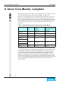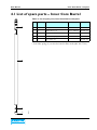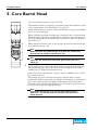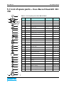
1
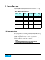
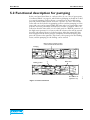
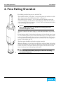
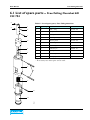
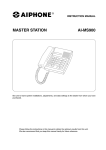
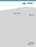
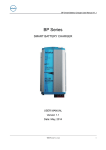
User manual
Wireline WL103/80
Doc. no.: WL103/80e.02
User Manual
Table of contents
1. Introduction
............................................................................................3
1.1 Description ...........................................................................................3
2. Safety Instructions
..............................................................................4
2.1 Recommendations ..............................................................................6
2.2 Wire Handling ......................................................................................7
2.2.1 Winding of wire .............................................................................7
3. Outer Core Barrel, complete
.......................................................8
3.1 Fitting of Outer Core Barrel ............................................................8
3.2 List of spare parts – Outer Core Barrel ........................................9
4. Inner Core Barrel, complete
.......................................................10
4.1 List of spare parts – Inner Core Barrel ........................................11
5. Core Barrel Head
..............................................................................12
5.1 List of spare parts – Core Barrel Head 601 222 790 ................13
5.2 Functional description for pumping .............................................15
6. Free Falling Overshot
......................................................................16
6.1 List of spare parts – Free Falling Overshot 601 222 794 .........17
7. Wireline 103/80, Component Parts .........................................18
2 · Doc. no.: WL103/80e.02
User Manual
Introduction
1. Introduction
The Sandvik Wireline System (WL) is available in dimensions of 46, 56,
66, 76 and 103 mm. The 66, 76 and 103 mm dimensions include a triple
variant with an extra inner tube.
Table 1: Different Wireline Systems
System
Hole
dimension
Core
dimension
Corearea in
% of hole
area
Tube
ext./int.
dim.
Tube
weight
kg/m
WL46
Ø47.0
Ø28.8
37.5
Ø43.2/35.2
3.9
WL56/39
Ø56.8
Ø39
47.1
Ø53.2/45.2
4.9
WL56/42
Ø56.8
Ø41.2
52.6
Ø53.2/47.2
3.8
B60
Ø60
Ø39
Ø55.6/46
6.0
WL66
Ø67.1
Ø50.5
56.6
Ø63.9/57.0
5.1
WL66-3
Ø67.1
Ø45
47.0
Ø63.9/57.0
5.1
WL76
Ø76.3
Ø57.5
56.8
Ø73.2/64.4
7.5
WL76-3
Ø76.3
Ø51
44.7
Ø73.2/64.4
7.5
WL103
Ø102.8
Ø80
60.9
Ø98/88.8
10.6
1.1 Description
For recovery in drill holes inclined at an angle of more than 60o from the
horizontal plane there is a free falling overshot (see chapter “Free Falling
Overshot” on page 16).
The WL core barrels are available in lengths of 1.5 and 3.0 m.
Drill bits for WL103 are manufactured as standard with an external
diameter of 102.5 and reaming shell of 102.8 mm.
Remark
When drilling with an oversize bit and reaming shell an
oversized drill rod connection should be used.
Doc. no.: WL103/80e.02 · 3
Safety Instructions
User Manual
2. Safety Instructions
!
Ì
WARNING
When handling Wireline it is important to inspect the wire
visually, since a broken wire can cause injury to personnel or
damage the equipment. When the wire starts to look
damaged it should be shortened.
!
Ì
WARNING
There is a risk of injury from the wire during Wireline
drilling. This risk is greatest between the Wireline windlass
and the top of the mast. Do NOT enter this area when the
wire is in operation. There is also a risk of getting trapped
round the drum, in the wire spreader on the drum, and at
the pulley on the mast. Remember that the wire can split up,
which can lead to severe cut injuries. Never grip the wire
when it is in motion.
!
Ì
WARNING
When handling Wireline the inner tube can release on
detachment and come sliding out of the hole at high speed.
!
Ì
WARNING
When the core barrel is emptied from the drill bit there is
a risk of injuring the hands and fingers. The core can come
sliding out from the core barrel at high speed. NEVER place
the hands and fingers under the core barrel, place them is
such a way that the core can pass without causing injury.
!
Ì
WARNING
The drill rods are exposed to a higher load and heavier
vibrations during upward drilling. The risk of drill rods
braking when they are worn is therefore increased. If the
rods break during the drilling the rod holder will be open,
which causes the rod string to slide out from the hole. For
this reason, place the panel at a safe distance from the
barrier.
!
Ì
WARNING
The risk of injury increases more than normal during upward
drilling.
4 · Doc. no.: WL103/80e.02
User Manual
Safety Instructions
!
Ì
WARNING
Cuff wrenches must under NO CIRCUMSTANCES be used
on the rods when they are rotated by means of the machine.
They can come loose and injure the operator, or cause pinch
injuries on the hands and fingers.
!
Ì
WARNING
Remember to secure the machine in a reliable manner when
it is anchored to the rock. Make sure to inspect the
attachment during operation to make sure the machine does
not come loose.
!
Ì
WARNING
Remember that you should have the opportunity to reach, or
have regular contact with those around you if you should
become injured when using the machine.
Doc. no.: WL103/80e.02 · 5
Safety Instructions
User Manual
2.1 Recommendations
• Check the threads on the drill rods regularly. If the threads are damaged
they can damage other rods they are attached to. Pay extra attention to
the water swivel tube.
• Make sure that the threads are properly engaged with each other before
the rods are screwed together by means of the machine.
• Make sure that the rod does not break during threading (rod support
and guides).
• Make sure to lubricate the threads.
Note
Always lubricate the drill rod threads with grease that is
suitable for high pressure. Special thread lubricant is best.
• Avoid rotating so fast that the threads are “knocked” together.
• Check that the threads are free from dirt and undamaged.
• Avoid too many tough shapening. Use a lower water flow instead for
hard rock.
• Make sure that lifting function on the machine functions during the rod
threading, and that the “float position” works.
• If the threading on one rod should get damaged during making of joint,
both rods should be replaced.
6 · Doc. no.: WL103/80e.02
User Manual
Safety Instructions
2.2 Wire Handling
2.2.1 Winding of wire
Wire with the lay to the
WL-2
Wire with the lay to the
Figure 1. Wire handling
Doc. no.: WL103/80e.02 · 7
Outer Core Barrel, complete
User Manual
3. Outer Core Barrel, complete
The numbers bellow, in brackets, correspond against the numbers in table
“List of spare parts, Outer Core Barrel” on page 9.
The core barrel drill rod adaptor (1) has tungsten carbide inserts so that it
can be guided up and therefore minimize the hole deviation.
3.1 Fitting of Outer Core Barrel
The outer landing ring (LY) (4) is fitted in the adapter tube’s (5) female
thread, with the internal collar facing upwards.
The latch housing (3) locks the outer landing ring (4).
Remark
The landing ring should be replaced after drilling
approximately 500 m.
The latching ring (2) is fitted on the latch housing’s (3) female thread.
The drill rod adaptor (1) locks the latching ring.
The latching ring can be reversed after a period of use if the edge has
become worn.
The outer tubes are of standard lengths 1.5 m or 3.0 m.
On those occasions when the outer tube is taken up for inspection a careful
check should be made that the outer landing ring and latching ring are in
place and undamaged.
The inner tube is locked upwards in the outer tube in that the core barrel
head latches support the latching ring. The inner tube is fixed downwards
in that the outer landing ring has a smaller diameter than the core barrel
head’s landing ring.
The tensile force when breaking the core is transferred from the core lifter
case to the drill bit in that the inner tube connection is flexible in the axial
plane (the core lifter case “rests” on the bit).
Before recovery the core is broken and the core barrel lifted 3-6 m. This
prevents drill cuttings that drop back into the hole collecting inside the
outer tube.
WL-27
Freshing the inner tube to mismatch when sent back.
8 · Doc. no.: WL103/80e.02
User Manual
Outer Core Barrel, complete
3.2 List of spare parts – Outer Core Barrel
Table 2: List of spare parts, Outer Core Barrel
1
No.
Quantit
y
Part
1
1
Drill rod adaptor, right-hand
601 222 770
2
1
Latching ring
601 222 771
3
1
Latch housing
601 222 772
4
1
Outer landing ring
601 222 773
5
1
Adaptor tube
L = 331 mm
601 222 774
6
*
Outer tube, 1.5 m
L = 1 608 mm
501 220 285
6.1
*
Outer tube, 3.0 m
L = 3 108 mm
501 220 286
7
1
Reaming shell
8
1
Drill bit
2
Remarks
Part no.
3
4
5
6
8
WL-26
7
Doc. no.: WL103/80e.02 · 9
Inner Core Barrel, complete
User Manual
4. Inner Core Barrel, complete
The numbers bellow, in brackets, correspond against the numbers in table
“List of spare parts, Inner Core Barrel, complete” on page 11.
Always use cuff wrenches when working with the inner tube (2) and core
lifter case (4). Check the function of the core lifter spring (3) after each
recovery. If the inner tube is clamped oval, or otherwise damaged, the inner
tube can stick in the drill rod or outer landing ring. A landing ring for the
core barrel head can be used to check that the inner tube has not been
deformed.
Table 3: Estimated times for pumping in Inner Core Barrel
System
Volume drill
rod
Speed with water
flow of
40 l/min.
Time to 100 m
with water flow of
40 l/min.
WL46/29
1.0 l/m
40 m/min.
2.5 min.
WL56/39
1.6 l/m
25 m/min.
4 min.
WL56/42
1.7 l/m
24 m/min.
4 min.
2.6 l/m
16 m/min.
6 min.
3.3 l/m
12 m/min.
8 min.
6.2 l/m
7 m/min.
15 min.
WL66/45
WL66/50.5
WL76/51
WL76/57.5
WL103
WL-28
The pumping in time for the inner core barrel is part of the total handling
time. If the Sandvik System with pumping of the inner tube or lifter is used
it is possible to obtain an indication of when they are in position. This
ensures significant time savings since the drilling or recovery of the inner
core barrel can be started immediately. How long the pumping takes
depends on how much water can flow in the gap between the core barrel
and hole wall. This time can be reduced by increasing the pressure of the
water, or increasing the gap between the drill rod and hole wall. If the gap
is increased between the drill rod and hole this increases the risk of
deviated holes.
10 · Doc. no.: WL103/80e.02
User Manual
Inner Core Barrel, complete
4.1 List of spare parts – Inner Core Barrel
Table 4: List of spare parts, Inner Core Barrel, complete
1
No
.
Quantity
Part
Remarks
Part no.
1
1
Core barrel head
2
1
Inner tube 1.5 m
L = 1 600 mm
601 222 777
2.1
1
Inner tube 3.0 m
L = 3 100 mm
601 222 778
3*
1
Core lifter spring, standard
601 222 779
4
1
Core lifter case
601 222 768
601 222 790
* Core lifter spring (3) can also be found in flatt mode (601 222 779-1).
2
4
WL-25
3
Doc. no.: WL103/80e.02 · 11
Core Barrel Head
User Manual
5. Core Barrel Head
Core barrel head has part no. 601 222 790.
The numbers bellow, in brackets, correspond against the numbers in table
“List of spare parts, Core Barrel Head” on page 13.
Check that the latches (2) move freely and that the O-ring (1) and tubular
pin (3, 4) are undamaged.
When checking the latches the lifter tip is inserted in the core barrel head.
The back edge of the lifters should then be inside the outer dimension of
the latch housing. If not, the tubular pin is probably crooked or the hole in
the latch worn.
When fitting the release valve (9) the spring (10) must be turned with the
rivet from the release valve.
Note
Make sure that the cylindrical pin (12) does not catch in the
thread and can easily be moved in its slot.
Note
WL-29
Lubricate the core barrel head with grease every time it is
taken up.
Use enough grease to ensure that fresh grease is pressed out through the
bearing housing (18). Oil in the release valve through the hole at the
landing ring (7). Wipe off all surplus grease.
If the release valve jams there is a reamer (part no. 300 025 325) to clean
the release valve seat.
The landing ring core barrel head is fitted so that the hole is turned
backwards on the bearing shaft (14). Fit the latch housing (5) [with spacer
(6)] on the valve housing, and tighten. When fitting the bearing unit it
should be noted that the thrust ball bearing (17) must be turned correctly
for the grease to pass through the bearing.
Note
The thrust ball bearing (17) washers have different hole
diameters. The washer with the smallest hole diameter is
fitted upwards.
12 · Doc. no.: WL103/80e.02
User Manual
Core Barrel Head
5.1 List of spare parts – Core Barrel Head 601 222
790
1
2
Table 5: List of spare parts, Core Barrel Head
2
3
2
4
5
3
6
No.
Quantit
y
Part
Remarks
Part no.
1
1
O-ring
59.5 x 3.0
300 012 695
2
4
Latch
3
4
Tubular pin
4.0 x 36
300 020 157
4
4
Tubular pin
3.0 x 26
300 015 310
5
1
Latch housing
600 222 784
6
1
Spacer
601 222 782
7
1
Landing ring core barrel head
601 222 785
8
1
Stop screw
300 012 531
9
1
Release valve
601 222 344
10
1
Spring
601 222 378
11
1
Valve housing
601 222 789
12
1
Cylindrical pin
300 022 671
601 224 419
7
8
9
10
11
12
13
14
13
1
O-ring
15
14
1
Bearing shaft
601 222 769
16
15
1
Spacer
601 222 775
17
16
1
Thrust washer
601 222 776
17
1
Thrust ball bearing
300 011 140
18
1
Upper bearing housing
601 222 788
19
2
Radial ball bearing
300 011 139
20
1
Washer
601 222 795
21
1
Spring
301 011 142
22
1
Bushing
601 222 783
23
1
Screw
601 222 786
24
1
Quick coupling
300 027 153
25
1
Lower bearing housing
601 222 787
26
1
Grease nipple
300 015 242
18
19
20
21
32.2 x 3.0
300 012 688
22
19
23
26
25
WL-23
24
Doc. no.: WL103/80e.02 · 13
Core Barrel Head
14 · Doc. no.: WL103/80e.02
User Manual
User Manual
Core Barrel Head
5.2 Functional description for pumping
In the core barrel head there is a release valve (9), see “List of spare parts,
Core Barrel Head” on page 13, which before pumping in should be locked
in a special pumping position. Insert a screwdriver in the latch housing,
press the release valve forward and turn a quarter of a turn. The release
valve will now be locked in its pumping position and the pumping in of the
inner tube can now be started. When the inner tube is in position the water
pressure increases powerfully and the flow of water is stopped. This is an
indication that the inner tube is in it locked position. With the retention of
the high water pressure for a few seconds the release valve will be pressed
forward and released from its locked position. After the pump flow has
been stopped and the water pressure completely drained, the spring will
press the release valve upwards. This forms a free passage for the flushing
water, and the pumping for the drilling can be started.
Release valve in pumping position
so that it blocks the flow of water
Pumping
9
9
Water flow
The latches lock
against the stop
WL-9
Drilling position
Figure 2. Core barrel head
Doc. no.: WL103/80e.02 · 15
Free Falling Overshot
User Manual
6. Free Falling Overshot
Free falling overshot has part no. 601 222 794.
The numbers bellow, in brackets, correspond against the numbers in table
“List of spare parts, Free Falling Overshot” on page 17.
The overshot has a swivel (1, 4, 5) in its upper end, which prevents the
wire from twisting. A safety device [shear pin (3)] is built into the swivel
and is intended to break at approx. 1.5 tons. This is to eliminate the risk of
a cut wire being left in the hole.
Remark
When double shear pins are fitted the breaking point load
increases to approx. 3 tons.
The wire is fitted in the wire clamp (1) and locked with three stop screws
(2).
Fit the bearing shaft (5) in the bearing housing (4), then fix the wire clamp
(1) on the bearing shaft (5) by means of the shear pin(s) (3). Lubricate the
surfaces between bearing housing and wire clamp with grease. The bearing
housing is then filled with grease before it is fitted on the wire weight by
means of the tubular pin (8).
The shear pins should be replaced at regular intervals.
When the lifting tip (11) moves down into the core barrel head, the latches
will be released from the locking ring. When the lifting tip have passed the
latches, the inner core barrel will be locked against the overshot and the
inner core barrel can be hoisted up by the wire.
WL-30
Note
16 · Doc. no.: WL103/80e.02
When the edge of the lifting tip begins to be worn the lifting
tip should be replaced.
User Manual
Free Falling Overshot
6.1 List of spare parts – Free Falling Overshot 601
222 794
2
Table 6: List of spare parts, Free Falling Overshot
1
No.
Quantity
Part
Part no.
2
1
1
Wire clamp
601 222 729
2
3
Stop screw
300 027 148
3
1*
Shear pin
300 025 423
4
1
Bearing housing
601 222 791
5
1
Bearing shaft
601 222 728
6
1
Lock ring
300 011 143
7
1
Wire weight
601 222 792
8
2
Tubular pin
300 011 157
9
1
Spring
300 011 141
10
1
Tubular pin
300 015 971
11
1
Lifting tip
601 222 793
2
3
4
5
6
* If necessary two shear pins can be used.
7
8
9
10
WL-31
11
Doc. no.: WL103/80e.02 · 17
Wireline 103/80, Component Parts
User Manual
7. Wireline 103/80, Component Parts
Drill bit 102.5 - 80, Reaming shell 102.8, Drill rod 98 - 88.8 mm
Table 7: Wireline 103/80, Component parts
18 · Doc. no.: WL103/80e.02
Component Parts
Part no.
Core barrel, complete WL103 x 1500
601 222 748
Core barrel, complete WL103 x 3000
601 222 749
Outer tube, complete WL103 x 1500
601 222 750
Outer tube, complete WL103 x 3000
601 222 751
Inner tube, complete WL103 x 1500
601 222 752
Inner tube, complete WL103 x 3000
601 222 753
Core barrel head, complete WL103
601 222 790
Free falling overshot for downward hole, complete
601 222 794
Water swivel
501 012 140
Adapter, water swivel
501 222 824
Drill rod WL103, 98 x 1500
601 222 766
Drill rod WL103, 98 x 3000
601 222 767
Adapter WL103 box x 113 pin
501 222 821
Adapter WL103 box x WL73 pin
501 222 822
Adapter WL103 pin x WL73 box
501 222 823