1
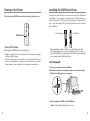
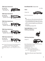
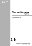
User’s Manual
Thank you for purchasing our product.
Carefully read this instruction manual
before using this unit.
Copyright 2004 T&D Corporation. All rights reserved.
2004.08 16004374040
Notices about this User’s Manual
In order to properly use this product, please carefully read this manual before
using.T&D Corporation accepts no responsibility for any malfunction of and/or
trouble with this product or with your computer that is caused by the improper
handling of this product and will deem such trouble or malfunction as falling
outside the conditions for free repair outlined in the attached warranty.
- All rights of this User’s Manual belong to T&D Corporation. It is prohibited to
use, duplicate and/or arrange a part or whole of this User’s Manual without
the permission of T&D Corporation.
- Microsoft and Windows are registered trademarks of Microsoft Corporation
USA and are binding in the USA and all other countries. Company names
and product names are trademarks or registered trademarks of each
company.
- Specifications, design and other contents outlined in this manual are subject
to change without notice.
- On screen messages in this manual may vary slightly from the actual
messages.
- Please notify the shop where you purchased this product or T&D Corporation
of any mistakes, errors or unclear explanations in this manual. T&D Corporation
accepts no responsibility for any damage or loss of income caused by the use
of our product.
- This product has been designed for private or industrial use only. It is not for
use in situations where strict safety precautions are necessary such as in
connection with medical equipment, whether directly or indirectly.
- We are not responsible for any malfunction or trouble caused by the use of
our product or by any problem caused by the use of measurement results
of our unit. Please be fully aware of this before using our product.
- Some of our products, which come under the category of strategic goods in
foreign trade law, need the permission of the Japanese government to be
exported outside of Japan.
- This User’s Manual cannot be reissued, so please keep it in a safe place.
- Please read the warranty and provisions for free repair carefully.
i
FCC Compliance Statement for American Users
This device complies with Part 15 of the FCC Rules.
Operation is subject to following two conditions: (1) this device may not
cause harmful interference. and (2) this device must accept any interference
received, including interference that may cause undesired operation.
Note: This equipment has been tested and found to comply with the limits for
a Class A Digital Device, pursuant to Part 15 of the FCC Rules. These limits
are designed to provide reasonable protection against harmful interference
in a residential installation. This equipment generates, uses and can radiate
radio frequency energy and, if not installed and used in accordance with the
instructions, may cause harmful interference to radio communications.
However, there is no guarantee that interference will not occur in a particular
installation. If this equipment does cause harmful interference to radio or
television reception, which can be determined by turning the equipment off
and on, the user is encouraged to try to correct the interference by one or
more of the following measures:
-- Reorient or relocate the receiving antenna.
-- Increase the separation between the equipment and receiver.
-- Connect the equipment into an outlet on a circuit different from that to which the
receiver is connected.
-- Consult the dealer or an experienced radio/TV technician for help.
Warning
This equipment has been verified to comply with the limits for a Class A
personal digital device, pursuant to Subpart B of Part 15 of FCC Rules. Only
peripherals (computer input/output devices, terminals, printers, etc.) certified
or verified to comply with the Class A or B limits may be attached to this
equipment. Operation with non-certified or non-verified personal computer
and/or peripherals is likely to result in interference to radio and TV reception.
The connection of a non-shielded equipment interface cable to this equipment
will invalidate the FCC Certification of this device and may cause interference
levels which exceed the limits established by the FCC for this equipment.
You are cautioned that changes or modifications not expressly approved by
party responsible for compliance could void your authority to operate the
equipment.
ii
Safety Precautions and Instructions
DANGERS
To ensure safety be sure to obey all of the following
warnings.
Do not take apart, repair or modify the main unit.
Doing so may cause fire or electrocution.
The following items should be strictly obeyed for the safe usage of this unit,
and for protecting yourself and other people from bodily harm and/or damage
to property. To ensure the proper use of our product, please read the following
carefully and fully understand the contents.
If water or a foreign body enters into this unit,
immediately remove the batteries and stop using.
Continued use may cause fire or electrocution.
■ Explanation of Symbols
Explanation of Warning Symbols
DANGER
CAUTION
These entries are actions that absolutely under no
circumstance should be taken. The taking of such an action
may cause serious personal physical damage or death.
These entries are actions that if taken may lead to physical
injury or damage to persons or things.
Explanation of Picture Symbols
Denotes an important warning or caution.
Denotes a forbidden action. Inside or near the symbol will appear
another symbol giving details.
stands for DO NOT TAKE APART)
(EX:
Denotes an action that you must take.
Do not use this unit in wet or humid places, such
as a bathroom.
Store main units, sensors, batteries and
communication cables out of the reach of children.
It is dangerous to touch or swallow batteries.
If any smoke or strange smells are emitted from
the unit, immediately remove the batteries and stop
using.
Continued use may cause fire or electrocution.
Do not drop the unit, or expose the unit to a strong
impact. If that happens to the unit, immediately
remove the batteries and stop using.
Continued use may cause fire or electrocution.
This device is designed to measure and record
temperature and humidity. Do not use it for
any other purpose than to measure and record
temperature and humidity.
This unit is not water-resistant.
If the unit gets dirty, wipe it with a clean cloth and a mild
detergent.
Do not expose the unit to harmful gases or
chemicals. It may cause corrosion and/or other
danger to the unit and to people handling the unit.
iii
iv
CAUTIONS
Do not use batteries other than specified. Doing so
may cause fire or damage.
Battery terminals may provide insufficient contact
due to age or vibration.
This may lead to data loss.
Condensation may occur if the unit is moved from
one environment to another where the difference in
temperature is great.
Use the unit in an environment where the ambient
temperature is from -10 to 60℃ and the humidity is
90% RH (no condensation) or less.
To prevent damage to the unit from static
electricity, remove static electricity from your body
by touching metal around you (door knob, window
frame) before touching the unit.
Static electricity may cause not only damage to the
unit, but may cause breaks in or a loss of data.
If the unit will not be used for period of time, for
safety reasons please remove the battery.
If left in the unit, it may leak and lead to malfunctioning.
Please take extra caution when plugging in and
pulling out the USB plug while another USB device
such as CD-RW/HDD is in operation.
It may cause problems to your CD-RW or other device.
CAUTIONS
Do not use any other batteries than those that are
specified in this User's Manual.
It may cause a fire or other trouble including
malfunction.
Do not use or store the Thermo Recorder in any
of the following places. Doing so may cause
electrocution, fire and/or other adverse effects to
the device and/or your computer.
- Areas exposed to direct sunlight
This will cause the inside of the device to become
overheated and may cause fire, deformation, and/or
other damage including malfunction.
- Areas prone to strong magnetic fields
This may cause damage including malfunction.
- Areas exposed to water leakage
This may cause electrocution or other damage
including malfunction.
- Areas exposed to excessive vibration
This may cause injury, malfunction, damage or loss of
proper electrical contact.
- Areas near fire or exposed to excessive heat
This may cause damage including malfunction and
deformation.
- Areas prone to smoke, dust and dirt
This may cause damage including malfunction.
We shall not guarantee the operation of our device
if you have connected it to your computer using a
USB hub or a USB extension cable.
Please do not insert your fingers or any foreign
objects into any of the devices’ jacks.
v
vi
Cautions about using the Sensors
Cautions about using the temperature sensor TR-0106
The possible temperature measurement range for
this sensor is -40 to 110℃ . Please use it within this
range.
Cautions about using the Sensors
[Handling the temperature/humidity sensor]
-
The temperature/humidity sensor should probably be changed after a
period of about one year. After removing the sensor from its package,
please change the temperature/humidity sensor after one year’s usage.
During use the temperature/humidity sensor will accumulate impurities (dirt)
on the surface of the sensor causing the sensor's accuracy and sensitivity
to decrease. If the sensor is being used in a bad environment (smoky or
dusty places) it may be necessary to change the sensor sooner.
-
When the temperature/humidity sensor is not being used, please place it in
the attached vinyl bag with the drying agent included and store it in a cool
dark place with a temperature of between 5 to 25℃ and a humidity of below
30% RH.
-
Attached to the temperature/humidity sensor are two stickers: a wetness
detection sticker and a temperature detection sticker. If either of the stickers
shows abnormality, you should change the old sensor to a new one
immediately.
It is possible to use just one extension cable per
temperature sensor.
Cautions about using
the temperature/humidity sensor TR-3100
The sensor can measure temperature within the
range of 0 to 50℃ and humidity within the range
of 10 to 95% RH. Only use the sensor within these
ranges.
If extremely severe temperature changes occur, the
humidity measurements may appear abnormal.
Once the sensor's temperature becomes stable, the
measurements will return to normal.
Wetness Detection
Sticker
Temperature Detection
Sticker
This sensor is not waterproof. Do not get wet.
The temperature/humidity sensor cable cannot be
extended.
When measuring with the temperature/humidity
sensor in an environment of 0 to 50℃ and less
than 30% RH, the measurements may sometimes
fluctuate. This is not abnormal.
-
Wetness Detection Sticker
Informs you that the sensor has been wet.
Normal:
Under normal conditions, black
dots will appear on a white
background.
-
Temperature Detection Sticker
Informs you that the sensor measured a temperature measurement over 60℃ .
60
vii
Abnormal:
Under abnormal conditions, it
will turn to red.
Normal:
Under normal conditions, the
number「60」will lightly appear on a
pinkish white background.
60
Abnormal:
Under abnormal conditions, the
number「60」will clearly appear on a
red background.
viii
Contents
Safety Precautions and Instructions -----------------------------------------iii
About Thermo Recorder TR-71U/72U --------------------------------------- 1
Package Contents ---------------------------------------------------------------- 3
Part Names and Functions ----------------------------------------------------- 5
Installing the Battery ------------------------------------------------------------- 7
Turning on the Power ------------------------------------------------------------ 8
Installing the USB Device Driver ---------------------------------------------- 9
Windows XP: --------------------------------------------------------------- 9
Windows 2000: ---------------------------------------------------------- 12
Windows Me: ------------------------------------------------------------ 16
Windows 98: ------------------------------------------------------------- 19
Starting Recording from Main Unit Switch-------------------------------- 27
Outline
TR-71U/TR-72U Thermo Recorders are data loggers capable of measuring,
displaying and recording temperature and humidity data. TR-71U has two
temperature channels and TR-72U has one temperature and one humidity
channel. The data recorded into the TR-71U/TR-72U units can then be
downloaded quickly via USB cable to your computer whereby with our
exclusive software you can easily process the data into graphs, tables, save to
files and/or print it out. Moreover, it is possible to connect more than one unit
at the same time.
Basic Functions
Temperature Measuring Range : -60 to 155℃ (TR-71U)
The TR-71U with the sensor included in this package can measure and
record in a range of -40 to 110℃ , but by purchasing one of our optional
sensors it is possible to measure and record in the wider range of -60 to
155℃ . Please take a look at our full range of optional sensors to find one
to match your application.
Humidity Measuring Range : 10 to 95% RH(TR-72U)
The TR-72U with the sensor included in this package can simultaneously
measure and record temperature in a range of 0 to 50℃ and humidity in a
range of 10 to 95% RH.
Data Recording Capacity : 8000 readings × 2 channels
Setting Recording Interval from Main Unit Switch ---------------------- 28
One channel can record and hold up to 8000 measurement readings. If set
at a recording interval of 1 hour, a unit can continuously record for about
one year.
If Installation Fails -------------------------------------------------------------- 29
1 Year of Operation with just 1 AA Alkaline Battery
Specifications -------------------------------------------------------------------- 31
Optional Accessories ---------------------------------------------------------- 32
Warranty ------------------------------------------------------------------- on back
ix
About Thermo Recorder TR-71U/72U
Our low energy consumption design gives you one year of continuous
operation with only one AA alkaline battery. This gives you the freedom to
use the data loggers in places where they can be left alone for long periods
of time, such as, in transportation or refrigeration.
Note: Battery life varies depending upon the type of battery, the
measuring environment, the frequency of communication, and the ambient
temperature in which it is used. Specifications and explanations used in
this User's Manual are based on operations carried out with a new battery
and are in no way a guarantee of your actual battery life.
1
Battery Life Warning Display
When the battery power becomes low, a battery life warning signal will
appear in the unit’s LCD display. If the battery power becomes even lower
the unit will automatically go into sleep mode in order to protect the data.
15 Recording Intervals
Package Contents
The following items are included in the package:
【TR-71U】
Select from 15 Recording Intervals (from 1 second to 1 hour) to meet your
needs. Select from 2 Recording Modes
One-time Mode :When the number of recorded readings reaches 8000,
FULL " will appear in the unit’s LCD display and recording
will automatically stop.
Endless Mode :When the number of recorded readings reaches 8000, the
oldest data reading will be overwritten and recording will
continue.
Backup Function
Thermo Recorder TR-71U × 1 unit
When battery power becomes low, a battery life warning signal will appear
in the unit’s LCD display and if the battery power becomes even lower the
unit will automatically go into sleep mode in order to protect the data. In
sleep mode all normal operations will stop and it will become impossible to
switch on the power of the main unit.
Note: If the main unit remains in sleep mode for about 1 month without
a change of battery, or if the battery is left out of the unit for more than 2
minutes, all recorded data will be lost.
Current Readings Monitoring Display
AA Alkaline Battery
(LR6) × 1
T&D Recorder for Windows
Software CD-ROM × 1
USB Communication Cable
US-15C × 1
Temperature Sensor
TR-0106 × 1
With our exclusive software, you cannot only monitor the current
measurements at a set interval, but can view those measurements in a
continually changing graph. You can simultaneously display the current
measurements and corresponding graphs for the number of units you have
connected.
Adjustment Function
Bt setting adjustment values beforehand, you can record and display
the post-adjusted measurement values. You can choose from two
adjustment methods: 1-point and 2-point. Adjustment will be carried out
using an adjustment equation of Y=aX + b ; where X is the pre-adjusted
measurement value and Y is the post-adjusted value.
2
Hardware User’s Manual (Warranty) × 1
Software User’s Manual × 1
3
Part Names and Functions
【TR-72U】
Part Names
[FRONT]
Thermo Recorder TR-72U × 1 unit
T&D Recorder for Windows
Software CD-ROM × 1
DISPLAY
button
AA Alkaline Battery
(LR6) × 1
USB Communication Cable
US-15C × 1
Temperature Sensor
TR-3100 × 1
Sensor Jack
(Channel 1)
Software User’s Manual × 1
REC/STOP
button
DISPLAY :Pressing this button will change the LCD display mode.
INTERVAL :Pressing this button will display the currently set recording
interval.
REC/STOP:Pressing this button will start or stop recording.
[RIGHT SIDE]
Hardware User’s Manual (Warranty) × 1
INTERVAL
button
Sensor Jack
(Channel 2)
Only for TR-71U
[LEFT SIDE]
USB Cable Jack
Serial Cable Jack ※ 1
POWER Switch
※ 1 : Serial Communication Cable is an Optional Accessory.
4
5
Installing the Battery
LCD Display
1.Remove the battery cover form the back of the unit.
②
③
④
⑤
⑥
2.Insert 1 AA alkaline battery, making sure that the + and – are in the
correct direction.
- Always use a new battery.
⑦
①
⑧
① Channel Mark
The channel number of the measurement being displayed will appear.
② Recording Mark
The recording condition will appear.
ON :Recording in progress. BLINKING:Waiting for programmed start.
③ Data Capacity Scale
After every 2000 readings the scale will be marked from left to right.
④ COM Mark
This will appear when data is being sent or received.
ON:USB cable is connected. BLINKING:In communication with computer.
⑤ Recording Mode
ONETIME: When the number of recorded readings reaches 8000, "FULL "
will appear in the unit’s LCD display and recording will
automatically stop.
ENDLESS: When the number of recorded readings reaches 8000, the oldest
data reading will be overwritten and recording will continue.
⑥ Battery Life Warning Signal
When the battery power becomes low, this will appear in the LCD display. If
the battery power becomes even lower, SLP will appear and normal
operations will stop. If the
signal appears, please change the battery as
soon as possible.
⑦ Unit of Measurement
The unit of measurement ( ゚C, ゚F, % ) for the display will appear.
⑧ Measurements and Messages Area
Current measurements or operational messages such as FULL or SLP will
appear.
6
3.Replace and close the battery cover.
[Changing the Battery]
1.When battery power becomes low, a battery life warning signal will
appear in the unit’s LCD display.
If, at this time you change the battery, recording will continue uninterrupted
and all data will be saved for downloading.
2.If the battery is not changed and power becomes even lower, SLP will
appear in the LCD display.
The unit will automatically go into sleep mode in order to protect the data
and all normal operations will stop.
If you change the battery at this point, it is still possible to download all
saved recorded data.
3.If the battery is further left unchanged, the display will automatically
shut off.
If all battery power is lost, all data will be lost as well.
Note:
If a unit is left without a battery for more than 2 minutes, all data will be lost,
so please work quickly when changing the battery.
7
Turning on the Power
Installing the USB Device Driver
1. By holding in the POWER switch at the left side, the unit will turn on.
You will need to install this driver in order to use the device with a USB cable
and Windows. It is necessary for communication via USB between your
computer and any TR-71U/72U device. After installing, your computer will be
able to detect and recognize TR-71U/72U devices that have been connected
with a USB cable.
To the Computer
To the Main Unit
POWER Switch
[Turning OFF the Power]
By holding in the POWER switch, the unit will turn off.
- During recording, the power cannot be turned off. Please stop recording first
and then turn off the power.
-
When installing the software [T&D Recorder for Windows], the USB
Device Driver will also be copied to your hard disc. So, even if you do not
have the CD-ROM but have already installed [T&D Recorder for Windows]
you can easily install the USB Device Driver.
- Even if the power has been turned off, the recorded data will be saved.
However, if the battery power is totally lost, all data will be lost, so please
download data as soon as possible to avoid losing any necessary data.
For Windows XP:
1.Turn on your computer and open Windows.
2.After Windows has been completely started up, connect the supplied
USB cable to a USB port on your computer.
3.Insert the attached CD-ROM in the CD-ROM drive.
Caution: If the Installation Window opens, close it.
8
9
4.By connecting a data logger to the USB cable already connected to your
computer, the [Add Hardware Wizard] will automatically open.
5.By checking [Install the Software automatically (Recommended)] and
clicking [Next], the software will automatically be installed.
Checking After Connecting
1.Open the [Control Panel] and double click on [System] ; the system
properties will be displayed.
2.Click the [Hardware] Tab, and click the [Device Manager] button in the
Device Manager Area.
「Hardware」Tab
Check
[Next]
button
Device Manager
6.After installation has been completed, click the [Finish] button.
[Device Manager]
button
3.In the Device Manager Window, check to see if [USB Recorder 1] is listed
under [USB Recorder COM].
[Finish]
button
Caution: If the Driver is not automatically detected, please search by
specifying the place as (CD-ROM [Device Driver]) and install manually
from there.
10
「USB Recorder1」
11
6.Check [Search for a suitable driver for my device (recommended)]
and click the [Next] button.
For Windows 2000:
1.Turn on your computer and open Windows.
2.After Windows has been completely started up, connect the supplied
USB cable to a USB port on your computer.
Check
[Next]
button
3.Insert the attached CD-ROM in the CR-ROM drive.
※ If the Installation Window opens, close it.
4.By connecting a data logger to the USB cable already
connected to your computer, the [Found New Hardware Wizard] will
automatically open.
7.Check [CD-ROM] and then click the [Next] button.
5.By clicking the [Next] button, a window will open where you can
choose how you wish to find the driver file.
Check
[Next]
button
[Next]
button
12
13
Checking After Connecting
8.By clicking the [Next] button, installation will begin.
1.Open the [Control Panel] and double click on [System]; the system
properties will be displayed.
2.Click the [Hardware] Tab, and click the [Device Manager] button in the
Device Manager Area.
「Hardware」Tab
[Next]
button
Caution: If the Driver is not automatically detected, please search by
specifying the place as (CD-ROM [Device Driver]) and install manually
from there.
Device Manager
[Device Manager]
button
9.After completing installation, click the [Finish] button.
3.In the Device Manager Window, check to see if [USB Recorder 1] is listed
under [USB Recorder COM].
[Finish]
button
「USB Recorder1」
14
15
6.After completing installation, click the [Finish] button.
For Windows Me:
1.Turn on your computer and open Windows.
2.After Windows has been completely started up, connect the supplied
USB cable to a USB port on your computer.
[Finish]
button
Caution: If the Driver is not automatically detected, please search by
specifying the place as (CD-ROM [Device Driver]) and install manually
from there.
3.Insert the attached CD-ROM in the CR-ROM drive.
※ If the Installation Window opens, close it.
4.By connecting a data logger to the USB cable already connected to
your computer, the [Add New Hardware Wizard] will automatically
open.
5.Check [Automatic search for a better dirver (Recommended)] and click
the [Next] button to begin installation.
Check
16
[Next]
button
17
Checking After Connecting
For Windows 98:
1.Open the [Control Panel] and double click on [System]; the system
properties will be displayed.
1.Turn on your computer and open Windows.
2.Click the [Device Manager] Tab, and the [Device Manager] Window will
appear.
2.After Windows has been completely started up, connect the supplied
USB cable to a USB port on your computer.
「Device Manager」Tab
3.Insert the attached CD-ROM in the CR-ROM drive.
「USB Recorder1」
※ If the Installation Window opens, close it.
4.By connecting a data logger to the USB cable already
connected to your computer, the [Add New Hardware Wizard] will
automatically open.
3.Check to see if [USB Recorder 1] is listed under [USB Recorder COM].
5.By clicking the [Next] button, a window will open where you can
choose how you wish to find the driver file.
[Next]
button
18
19
6.Check [Search for the best driver your device (Recommended)] and
click the [Next] button.
8.Click [Next] to start the installation.
Check
[Next]
button
7.Check [Specify a location] and click the [Browse] button. Select the
[Device Driver] in the CD-ROM drive and click [Next].
[Next]
button
9.After completing installation, click the [Finish] button.
Check
[Browse]
button
[Finish]
button
[Next]
button
Caution: If the Driver is not automatically detected, please search by
specifying the place as (CD-ROM [Device Driver]) and install manually
from there.
20
21
Checking After Connecting
1.Open the [Control Panel] and double click on [System]; the system
properties will be displayed.
Connecting the Sensor
Connecting the Sensor.
[TR-71U]
2.Click the [Device Manager] Tab, and the [Device Manager] Window will
appear.
「Device Manager」Tab
If a temperature sensor is connected to only the ch. 2 jack, the internal
sensor will be used to measure for ch. 1.
- To avoid poor connections, be sure to push the sensor connector securely
into the jack.
-
Note:If a sensor extension cable is being used with the data logger
connected by USB to your computer, electromagnetic waves may cause
large errors in measurements.
「USB Recorder1」
[TR-72U]
3.Check to see if [USB Recorder 1] is listed under [USB Recorder COM].
Caution:When using the temperature/humidity sensor in environments
where the temperature is 0 to 15 and humidity under 30 RH, there may
occur changes in measurement readings. This is not a malfunction.
-
22
To avoid poor connections, be sure to push the sensor connector securely
into the jack.
23
[Handling the temperature/humidity sensor]
-
The temperature/humidity sensor should be changed after a period of about
one year. After removing the sensor from its package, please change the
temperature/humidity sensor after one year’s usage.
During use, the temperature/humidity sensor will accumulate impurities
(dirt) on the surface of the sensor causing the sensor's accuracy and
sensitivity to decrease. If the sensor is being used in a bad environment
(smoky or dusty places) it may be necessary to change the sensor sooner.
-
When the temperature/humidity sensor is not being used, please place it in
the attached vinyl bag with the drying agent included and store it in a cool
dark place with a temperature of between 5 to 25℃ and a humidity of below
30% RH.
-
Attached to the temperature/humidity sensor are two stickers: a wetness
detection sticker and a temperature detection sticker. If either of the sticker
shows abnormality, you should change the old sensor with a new one
immediately.
Wetness Detection
Sticker
-
Temperature Detection
Sticker
Wetness Detection Sticker
Informs you that the sensor has been wet.
Normal :
Under normal conditions, black
dots will appear on a white
background.
-
Abnormal :
Under abnormal conditions, it
will turn to red.
Temperature Detection Sticker
Informs you that the sensor measured a temperature measurement over
60℃ .
60
24
Normal :
Under normal conditions, the
number「60」will lightly appear on a
pinkish white background.
60
Starting Recording from Main Unit Switch
By pressing the REC switch on the main unit you can start a recording
session immediately.
Caution: If you wish to make changes to the device name, channel name,
recording mode or to any other recording conditions, you must make those
settings by connecting the device to your computer.
[Starting a Recording Session]
Press in the [REC/STOP] button on the front of the unit until the REC mark
appears in the display. When displayed, recording has begun.
REC mark lights up
Note:
- By starting a new recording session, all data currently saved in the unit will
be erased.
- Even if the unit is waiting for a programmed start, by pressing the [REC/
STOP] button until the REC mark appears, you can start a new recording
session immediately.
[Stop Recording]
You can stop a recording session by pressing the [REC/STOP] button
until the REC mark disappears from the display. When it has disappeared,
recording has stopped.
REC mark disappears
Abnormal :
Under abnormal conditions, the
number「60」will clearly appear on a
red background.
25
Setting Recording Interval from Main Unit Switch
If Installation Fails
You can make or change recording interval settings from the "INTERVAL"
switch on the front of the TR-71U/72U main unit.
If, during USB device driver installation, some trouble occurs that results in
a failure to install properly, the following display will appear in the Device
Manager.
1.Press in the [INTERVAL] button on the front of the device until the
recording interval appears in the display.
2.With each pressing of the [INTERVAL] button the recording
interval time will change. Press until the desired setting appears.
If this occurs, please re-install from the[USB Device]properties.
How to Re-install
《15 minutes》
《15 seconds》
1.In the Device Manager Window, right click on [USB Device] under
[Other Devices] to display the USB Device Properties.
3.When the desired recording interval appears, stop pressing the
[INTERVAL] button. Within a few seconds, the current measurement
readings will return to the display and the setting will be finished.
- By pressing the [INTERVAL] button during recording or while waiting for a
programmed recording to start, the currently set recording interval will be
displayed.
2.In the USB Device Properties Window, click on the [Reinstall Driver]
button to display the Installation Window. Follow the directions to
install.
[Reinstall Driver]
button
26
27
Specifications
Device Type
Optional Accessories
Temperatue Sensors(For TR-71U)
TR-71U
TR-72U
No. of Measurement
Channels
2 Channels
(Select from ch1. internal /
ch.2 external)
2 Channels
(1 Temperature / 1 Humidity)
Measurement Items
Temperature
Temperature
Humidity
Internal Temperature
Sensor
-10 to 60℃
-10 to 60℃
-
Attached Sensor
-40 to 110℃
0 to 50℃
10 to 95% RH
Optional Temp. Sensor
Measuring Accuracy
(with Attached Sensor)
-60 to 155℃
※1
Recording Interval
Recording Capacity
Recording Modes
LCD display
Power
± 5% RH
(at 25℃ 50% RH)
0.1℃
1% RH
Thermistor
Macromolecular
Humidity Sensor
Select from 15 choices: 1・2・5・10・15・20・30 seconds
1・2・5・10・15・20・30・60 minutes
8000 readings × 2 channels
Endless Mode / One-time Mode
(Ch1 only, Ch2 only, alternating display)Measurements,
Recording Status, Battery Life Warning, Amount of Recorded Data,
Unit of Measurement
AA alkaline battery (LR6)
About 1 year ※ 2
Battery Life
Data Backup
Interface
Activated when battery power is low or when switch is off (About 1 year)
USB Communication Cable (option: RS-232C)
USB Communication
Time
When downloading (1 unit of full data-about 8 seconds)
Dimensions /
Weight of Main Unit
H55 × W78 × D18 ㎜ / about 62 g (including one AA battery)
Working Environment
for Main Unit
Attached Sensors
Accessories included in
package
Temperature: -10 to 60℃
Humidity: under 90%RH (without condensation)
TR-0106 × 2
unit : millimeters
Cable Length : 0.6m
Thermal-Constant Time :
In the air : Approx. 15 Sec.
In agitated water : Approx. 2 Sec.
-
Average ± 0.3℃ (-20 to 80℃ )
Average ± 0.5℃ (-40 to -20 / 80 to 110℃ )
Measuring /
Display Resolution
Sensor
-40 to 110℃
TR-1106 Teflon-Shielded Sensor
TR-3100 × 1
TR-1220 Stainless Protection Sensor
Cable Length : 2.0m
Thermal-Constant Time :
In the air : Approx. 36 Sec.
In agitated water : Approx. 7 Sec.
TR-1320 Stainless Protection Sensor
Cable Length : 2.0m
Thermal-Constant Time :
In the air : Approx. 12 Sec.
In agitated water : Approx. 2 Sec.
Materials: ① Thermistor ② Stainless pipe(SUS316) ③ Teflon Compaction Tube
④ Teflon Resin(FEP) Shielded
Possible Measurement Range : -60 to 155℃ Sensor Temperature Durability : -70 to 180℃
Water Resistance : Splash Proof (Sensor and Cable)
Measurement Accuracy : Average ±0.3℃ (-20 to 80℃ )・Average ±0.5℃ (-40 to -20℃ /80 to 110℃ )
Average ±1.0℃ (-60 to -40℃ /110 to 155℃ )
unit : millimeters
TR-0106 TPE resin-Shielded Sensor
Cable Length: 0.6m
Thermal-Constant Time :
In the air : Approx. 75 Sec.
AA alkaline battery (LR6) × 1 / User's Manual (Warranty) × 1
USB cable × 1 (US-15C ; length 1.5 m)
Software set × 1 / User's Manual (Warranty) × 1
*1 : There are two types of temperature sensor for TR-71U depending on measurement
range. For details see Optional Accessories on p.29.
*2 : Battery life depends upon the measuring environment, recording interval, and quality
of the battery being used.
28
29
TR-0206 Stainless Protection Sensor
Sensor Extension Cable(Temp Sensor Only)
Cable Length : 0.6m
Thermal-Constant Time :
In the air : Approx. 75 Sec.
TR-1C30
unit : millimeters
Cable length : 3.0m
TR-0306 Stainless Protection Sensor
Cable Length : 0.6m
Thermal-Constant Time:
In agitated water : Approx 18 Sec.
Materials: ① Vinyl Coated Electrical Wire
※ Only stainless section is water resistant
TR-0406 Stainless Protection Sensor
Cable Length : 0.6m
Thermal-Constant Time :
In agitated water : Approx 20 Sec.
※ Only stainless section is water resistant
Note:
- Only one cable per sensor. When using the extension cable there will be
a +0.3℃ at normal temperature and at -50℃ a gap of +0.5℃ may occur.
- If a sensor extension cable is being used with the data logger connected
by USB to your computer, electromagnetic waves may cause large errors
in measurements.
- Do not use the Extension Cable with TR-72U.
Temp / Humidity Sensors(For TR-72U)
TR-0506 Stainless Protection Sensor
TR-3100 Temp / Humidity Sensor
Cable Length : 0.6m
Thermal-Constant Time :
In agitated water : Approx 20 Sec.
※ Only stainless section is water resistant
TR-0706 Stainless Protection Sensor
TR-3110 Temp / Humidity Sensor
Cable Length : 0.6m
Thermal-Constant Time :
In agitated water : Approx 18 Sec.
Cable length : 1m
※ Only stainless section is water resistant
Materials: ① Thermistor ② TPE resin-shielded sensor ③ TPE resin-shielded wire ④ M3Screw Hole
⑤ Compacion Tube ⑥ Stainless pipe(SUS304) ⑦ Stainless pipe(SUS316)
Possible Measurement Range : -40 to 110℃ Sensor Temperature Durability: -50 to 115℃
Measurement Accuracy : Average ±0.3℃ (-20 to 80℃ )・Average ±0.5℃ (-40 to -20℃ /80 to
110℃ )
Materials: ① Temperture/humidity sensor ② Polypropylene resin ③ Vinyl Coated Electrical Wire
Possible temperature measurement range : 0 to 55℃
Possible humidity measurement range : 10 to 95% RH
Sensor temperatur resistance : -10 to 55℃
humidity measurement accuracy : ± 5% RH(At 25℃ 50% RH)
Service life : 1 year (under normal operational conditions)
Operational conditions : Without dew condensation, water leakage or effect from
corrosive gas or organic solvents.
Note: An Extension Cable cannot be used with Temperature/Humidity
Sensors.
30
31
Serial Communication Cable (for TR-71U/72U)
TR-07C Serial Communication Cable
Cable Length:about 1.0 m
Connector Type:Specialized Connector
D-sub9pin
For communication with computer
TR-4C10 Serial Communication Cable
Cable Length:about 1.0 m
Connector Type:Specialized Connector
D-sub9pin
For communication with RTR-57C
Wall Attachment(for TR-71U/72U)
unit : millimeters
TR-07K2 Wall Attachment
Included: screws × 2
double-sided tape × 1
Compatible Devices:TR-71U/72U
75
52
3
For product information or questions contact us at:
Provisions for Free Repair
5652-169, Sasaga, Matsumoto City, Nagano, 399-0033 Japan
Tel: +81-263-27-2131
Fax: +81-263-26-4281
E-mail: [email protected]
Office Hours :Monday to Friday 9:00-12:00/13:00-17:00
(GMT +9:00 Tokyo Time)
[Home Page]
We have opened an English Homepage called "T&D Online" for your
convenience. Here you can find information about our company, news,
products, upcoming events, software and user’s guides downloads, as well
as, other support. Please stop by and see what we have to offer.
h t t p : / / www.tandd.jp/
1. If the unit does not work properly despite the fact that the customer
used it properly and in line with the User's Manual, the unit shall be
repaired free of charge through the distributor which sold the unit.
2. If the customer requests free repair because of trouble within the
warranty period, bring or send the unit along with the warranty to the
dealer. A service charge may be added if a repairperson must be sent
out to the place of use for repair.
3. If you have moved after purchasing, or the product was received as
a gift, or there are difficulties contacting the shop from which you
purchased the unit, please contact T&D directly for service.
4. Free repair is not available in the following cases even though it is
within the warranty period:
1. Trouble or damage was caused by careless operation, natural
disaster, fire, public pollution, or use of a power source other than
specified.
2. If repair, adjustment, disassembly or modification of the unit
has been carried out by a person other than a T&D authorized
engineer.
3.Trouble or damage was caused by transportation, movement or
dropping of the unit after purchase.
Thermo Recorder TR-71U/TR-72U User's Manual
Published by T&D CORPORATION
Copyright 2004 T&D Corporation. All rights reserved.
This is printed on 100% recycled paper.
4.Failure to submit the Warranty or failure to fill in all items required
in the Warranty.
5. The Warranty cannot be reissued.
This Warranty only promises customers free repair within the period
and conditions clarified in this Warranty. Therefore, the customer's
legal rights will not be limited by this Warranty. For further information
on repair and others service questions after the termination of the
warranty period, contact your dealer.