1
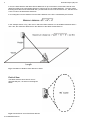
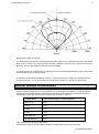
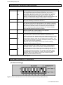
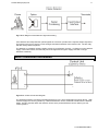
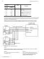
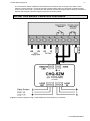
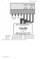
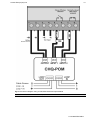
IFD-E Flame Detector User Manual 2 Hochiki Europe (UK) Ltd General Description The flame detector is designed for use where open flaming fires may be expected. It responds to the light emitted from flames during combustion. The detector discriminates between flames and other light sources by responding only to particular optical wavelengths and flame flicker frequencies. This enables the detector to avoided false alarms due to such factors as flicking sunlight. Electrical Considerations The flame detector can be connected in many different electrical configurations depending on the application. The detector requires a 24Vdc (14Vmin. to 30Vmax.) supply to operate. The detector can be connected as a two-wire loop powered device increasing its supply current to signal that a flame has been detected. See Fig 8. The supply connections to the detector are polarity sensitive. Also available are volt free contacts from two internal relays RL1 (Fire) and RL2 (Fault or pre-alarm). Using the relay contacts connected in a four-wire configuration the detector status can be signalled back to control equipment. See Fig 9. Removing the detector front cover provides accesses the detector terminals and configuration DIL switch. See Fig.4. Alarm Response Modes The detector is normally configured to latch into an alarm state when a flame is detected. The supply to the detector has to be broken in order to reset the detector. The configuration DIL switch within the detector can be set to place the detector into a non-latching mode. The detector can then also produce proportional analogue current alarm signals, in other words, 8-28mA or 4-20mA. In non-latching mode the detector only produces an alarm signal when a flame is in view resetting itself to normal when the flame has gone. 2-3-0-808/ISS4/JAN14 Hochiki Europe (UK) Ltd 3 Application for Flame Detectors Flame detectors are used when detection is required to be: Unaffected by convection currents, draughts or wind Tolerant of fumes, vapours, dust and mist Responsive to a flame more than 25m away Fast reacting The detector is capable of detecting the optical radiation emitted by burning material even noncarbonaceous materials. e.g. Hydrogen Numerous other potential fire sources can be detected such as: Liquids Solids Gases ● Aviation Fuels (kerosene) ● Coal ● Butane ● Ethanol ● Cotton ● Fluorine ● Methylated Spirits ● Grain & Feeds ● Hydrogen ● n-Heptane ● Paper ● Natural Gas ● Paraffin ● Refuse ● Off Gas ● Petrol (gasoline) ● Wood ● Propane Typical applications examples are: ● Agriculture ● Coal handling plant ● Pharmaceutical ● Aircraft hangars ● Engine rooms ● Power plants ● Atria ● Generator rooms ● Textiles ● Automotive industry ● Metal fabrication ● Transformer stations - spray booths ● Paper manufacture ● Waste handling - parts manufacture ● Petrochemical ● Woodworking Applications and Locations to Avoid: ● ambient temperatures above 55°C ● large IR sources – heaters, burners, flares ● close proximity to RF sources ● obstructions to field of view ● exposure to severe rain and ice ● sunlight falling directly on the detector optics ● large amounts of flickering reflections ● spot lighting directly on the detector optics Quantities Required and Positioning of Detectors The number of detectors required and their position depends on: the anticipated size of the flame the distance of the flame from the detector the angle of view of the flame detector The flame detector is designed to have a class 1 performance as defined in BS EN54-10:2002 on the high sensitivity setting. That is the ability to detect an n-heptane (yellow) fire of 0.1m² or methylated spirit (clear) fire of 0.25m² at a distance of up to 25m within 30 seconds. The detector can be set to have to a lower sensitivity setting equivalent to class 3 performance. Class 3 performance is defined as detecting the same size fires as for class 1 but at a distance of only 12m. 2-3-0-808/ISS4/JAN14 4 Hochiki Europe (UK) Ltd In fact, the flame detector will detect fires at distances of up to 40 metres, but the flame size at such distances needs to be proportionally greater in order to be sure of reliable detection. Thus the yellow flickering flame that can be detected at 25m, provided that its size is not less than 0.1m², will have to be 0.4m² in order to be detected at 40metres. In a rectangular room the distance from the flame detector to the fire is calculated by the formula: In the example shown in Fig 1 the room in which the flame detector is to be installed measures 20m x 10m x 5m; the maximum distance from the detector to the flame will therefore be: Fig 1 Calculation of distance from detector to flame Field of View The flame detector has a field of view of approximately 90°, as shown in the diagram below. Fig 2 Conical field of view of the flame detector 2-3-0-808/ISS4/JAN14 Hochiki Europe (UK) Ltd 5 Fig 3 Detector Field of View Plot The flame detector should be positioned at the perimeter of the room, pointing directly at the anticipated flame or at the centre of the area to be protected. If the detector cannot ‘see’ the whole of the area to be protected, one or more additional detectors may be required. The flame detector is not affected by normal light sources but should be positioned so that sunlight does not fall directly onto the viewing window. To meet the requirements of EN54:10 clause 5.4, where the ratio of the response points Dmax:Dmin should not exceed 1.41. The horizontal and vertical viewing angles α max should not exceed ±30°. Detector Window Contamination It is important to keep the detector window clean and checks should be carried out at regular intervals – determine locally according to the type and degree of contamination encountered – to ensure optimal performance of the flame detector. Although the IR detectors can detect flames when the window is contaminated, there may be a reduction of sensitivity as shown in Table 1. Contamination Typical percentage of normal response Water spray 75% Steam 75% Smoke 75% Oil film 86% Salt water film 86% Dry salt deposits 86% Table 1 IR Detector window contamination UV/IR detectors are more susceptible to window contamination and must be kept clean 2-3-0-808/ISS4/JAN14 6 Hochiki Europe (UK) Ltd Detector Interior IR Optics (IR optical flame sensors and filters) Supply ON (Green) (steady if detector functioning correctly) Fire (Red) (indicates a FIRE detected) Test (Yellow) (indicates detector in test mode) DIL Switch (select detector functions) Connection Terminals Fig 4 Detector with Front Cover removed Electrical Connections The flame detector has eight connection terminals as show in Fig 5. Removing the front cover of the flame detector accesses the connections. The cable is passed through the gland holes in the base of the detector. Note – When the IFD-E is used on a Conventional system a Fire Resistor will be required across the FLAME relay, the value of this resistor will be dependent on Control Panel, check with manufacturer. Fig 5 Electrical Connection Terminals (for Conventional system) 2-3-0-808/ISS4/JAN14 Hochiki Europe (UK) Ltd 7 Connection Terminal Descriptions Terminal No. Mnemonic Function 1 +IN Power Supply +V. +IN is the power supply input to the flame detector and is normally 24Vdc with respect to terminal 2. The current consumption of detector can be monitored to determine the detector status (Fault, Normal, Pre-alarm, Fire). If the detector is in latching mode then this supply line must be broken in order to reset the detector. A thermal fuse within the detector will blow and break the +IN connection if the detector operating temperature is exceeded. 2 -IN Power Supply 0V. –IN is the return path for the detector supply current. -IN is also internally connected to terminal 4. 3 +R Remote Detector Test Input +V. No connection to +R is necessary if the detector optical and circuit test feature is not required. If 24Vdc is applied to terminals 3 and 4 the detector internal optical test sources will activate to simulate a flame. The detector yellow test LED will flicker to indicate an optical test is progress. The detector will then alarm indicating that the test was successful. 4 -R Remote Detector Test Input 0V. No connection to -R is necessary if the detector optical and circuit test feature is not required. -R is internally connected to terminal 2. RL1 Flame Relay RL1. This volt free contact is normally open (N/O) and only closes when a flame has been detected. If the detector is in latching mode (see DIL switch settings) the contact will remain closed once a flame has been detected. Only when the detector supply +IN is broken will the detector reset and the contact open once again. The contact can be changed to a normally closed (N/C) state by moving the link on JP1 in the rear of the detector. Maximum relay contact ratings: Power=3W, Current=0.25Amp, Voltage=30Vdc. Resistive loads only. RL2 Fault or Pre-alarm Relay RL2. This volt free contact is normally closed (N/C) if the detector has no faults and the supply voltage between terminals +IN and –IN is the correct value. If the detector mode is changed (see DIL switch settings) this relay can be de-energised to reduce the detector current consumption. Alternatively RL2 can be set to provide a pre-alarm fire signal. The normal contact state can be changed state by moving the link on JP2 in the rear of the detector. Maximum relay contact ratings: Power=3W, Current=0.25Amp, Voltage=30Vdc. Resistive loads only. 5 6 7 8 Table 2 Connection Terminal Descriptions Selectable Detector Functions (DIL Switch Settings) Fig 6 DIL Switch with Detector Front Cover Removed (Normal factory settings shown) 2-3-0-808/ISS4/JAN14 8 Hochiki Europe (UK) Ltd Selectable Functions DIL Switch Settings Relay RL2 Function: 1 2 RL2 off (No fault relay) – For lowest detector current consumption. 0 0 RL2 off, or UV pre-alarm, flame or electrical sparks detected. 1 0 RL2 energised on IR pre-alarm 0 1 RL2 detector fault relay (Energised if detector powered and no faults) 1 1 Detector Supply Current (Detector Status): [-/ = see Output Mode below] 3 4 Low current mode, 3mA / 9mA (RL1 Only), 8mA / 14mA (RL1 & RL2) 0 0 Two-wire current signalling only. No relays operating. 4-20mA, 4/20mA 1 0 Two-wire current signalling 8-20mA, 8/20mA and both relays operating. 0 1 Two-wire current signalling 8/28mA and both relays operating. 1 1 Output Mode: (-) Proportional analogue supply current. (/) Step change, supply current. 5 Non-latching fire alarm signalling. (-) 0 Latching fire alarm signalling. (/) 1 Response Time: Faster response times reduce the optical interference immunity. 6 7 Slowest ≈ 8s 0 0 Medium ≈ 4s 1 0 Fast ≈ 2s 0 1 Very Fast ≈ 1s 1 1 Sensitivity: See EN 54-10 8 Note: Meets EN54-10:2002 at Class 1 only Low Class 3 0 High Class 1 1 denotes Factory settings Table 3 DIL Switch Settings Theory of Operation The detector responds to low-frequency (1 to 15 Hz.) flickering IR radiation emitted from flames during combustion. IR flame flicker techniques enable the sensor to operate through a layer of oil, dust, water vapour, or ice. Most IR flame sensors respond to 4.3µm light emitted by hydrocarbon flames. By responding to 1.0 to 2.7µm light emitted by every fire all flickering flames can be detected. Gas fires not visible to the naked eye e.g. hydrogen may also be detected. The triple (IR³) IR photoelectric detector, responding to neighbouring IR wavelengths, enables it to discriminate between flames and spurious sources of IR radiation. The combination of filters and signal processing allows the sensor to be used with little risk of false alarms in difficult situations characterised by factors such as flickering sunlight. Signal Processing The detector views the flame at particular optical wavelengths. The more differing optical wavelength signals available the better the detector is at discriminating between flames and false optical sources. The detector processes the optical signal information to determine if a flame is in view. This is achieved by comparing the signals with known flame characteristics stored within the detector. 2-3-0-808/ISS4/JAN14 Hochiki Europe (UK) Ltd 9 Fig 7 Block Diagram of the Detector Signal Processing If the detector has interpreted the optical signals as a fire then it produces the required output responses. This will be in the form of supply current changes and the illumination of the red fire LED. The fire relay will also change state if required. The detector is constantly checking itself to ensure it is performing correctly. If a fault occurs the detector supply current will reduce, the fault relay will de-energise and the green supply LED will no longer illuminate constantly. Basic Connection Information Fig 8 Basic 2 Wire Connection Diagram The simplest method of connecting the flame detector is in a 2-wire configuration as shown above. With a 24Vdc supply the current (i) drawn by a detector/detectors can be monitored to determine the detector status. The DIL switches within the detector can be set to produce different current values (i) to suit control systems. 2-3-0-808/ISS4/JAN14 10 Hochiki Europe (UK) Ltd Detector Supply Current i @ 24Vdc DIL Switch Setting Comment Normal Quiescent Current Alarm (Fire) Current 3mA 9mA 0 0 0 0 4mA 20mA 0 0 1 0 For 4-20mA systems, no relays 8mA 14mA 1 1 0 0 8mA 20mA 1 1 0 1 For 4-20mA systems & relays 8mA 28mA 1 1 1 1 Fire control panels 1 2 3 4 Lowest power configuration, RL1 only Lowest power configuration & relays Table 4 Detector Supply & Alarm Currents If the detector supply current falls below the normal quiescent current consumption then a fault is present. This could be simply an open circuit cable fault or a fault within the detector possibly due to the detector being taken over its rated temperature. Detectors can be connected in parallel increasing the overall quiescent current required. The alarm current signal will remain the same with the additional quiescent current drawn from other detectors. Fig 9 Basic 4 Wire Connection Diagram NOTE 1 Screened cable should be used with one end of the screen connected to earth. Also care should be taken not to run the detector cable next to power cables. NOTE 2 NOTE 3 R = To indicate fire to control unit or interface. For example, 470R EOL = End of line device required by some control units. This is required to monitor the cable to the detectors and prevent fault indications on the control unit. 2-3-0-808/ISS4/JAN14 Hochiki Europe (UK) Ltd 11 The circuit shown above enables the flame detectors to interface with most type of fire alarm control systems. The fire relay RL1 is used to switch the required alarm load ‘R’ to generate a fire alarm signal. An end of line device ‘EOL’ mounted in the last detector provides the system with the ability to monitor the detector fault relay RL2 and the integrity of the interconnecting cables. Hochiki CHQ Module Connection Information Fig 10 Connection Diagram using a CHQ-SZM Single Zone Monitor (or CHQ-MZ) 2-3-0-808/ISS4/JAN14 12 Fig 11 Connection Diagram using a CHQ-DIM Dual Input Module (or CHQ-S) 2-3-0-808/ISS4/JAN14 Hochiki Europe (UK) Ltd Hochiki Europe (UK) Ltd 13 Fig 12 Connection Diagram using a CHQ-POM Powered Output Module NOTE: The CHQ-POM has a variable output, this should be set at 30mA. 2-3-0-808/ISS4/JAN14 14 Fig 13 Connection Diagram using a CHQ-DZM Dual Zone Monitor (or CHQ-Z) 2-3-0-808/ISS4/JAN14 Hochiki Europe (UK) Ltd Hochiki Europe (UK) Ltd 15 Installation It is important that the detectors are installed in such a way that all terminals and connections are protected to at least IP20 with the detector cover fitted. The earth bonding terminals are provided for convenience where continuity of a cable sheath or similar if required. Adjustable mounting brackets and weather shields are available as shown below in Figs 14 and 15. Fig 14 Stainless Steel Adjustable Mount Fig 15 Stainless Steel Weather Shield Functional Testing When 24Vdc power is applied to the detector the green supply on indicator LED will illuminate. The fault relay RL2, if selected with the DIL switch, will energise and the contact between terminals 7 and 8 will close. If 24Vdc is applied to terminals 3 and 4 or terminal 3 is linked to terminal 1 the detector will perform a self-test. It does this by causing internal optical test sources to simulate the behaviour of flames and the detector will alarm. Alternatively a portable flame sensor test unit is available to generate simulated flame behaviour and test the detector a few metres in front of the detector. See Fig 16. Finally, provided it is safe to do so, carry out a flame test using a flickering flame source, such as a portable Bunsen burner. See Fig 17. A still non-flickering flame will not produce a response from the detector Fig 16 Portable Flame Detector Test Unit Fig 17 Portable Bunsen Burner 2-3-0-808/ISS4/JAN14 16 Hochiki Europe (UK) Ltd Service & Repairs Servicing of the fire protection system should be carried out by competent persons familiar with this type of system, or as recommended by the local regulations in force. Only the manufacturer or equivalent authorised body may carry out repairs to the flame detectors. In practical terms this means that flame detector may be repaired only at the manufacturer’s factory. Hochiki Europe (UK) Ltd Grosvenor Road, Gillingham Business Park, Gillingham, Kent, ME8 0SA, England Telephone: +44(0)1634 260133 Facsimile: +44(0)1634 260132 Email: [email protected] Web: www.hochikieurope.com Hochiki Europe (UK) Ltd. reserves the right to alter the specification of its products from time to time without notice. Although every effort has been made to ensure the accuracy of the information contained within this document it is not warranted or represented by Hochiki Europe (UK) Ltd. to be a complete and upto-date description. Please check our web site for the latest version of this document. 2-3-0-808/ISS4/JAN14