1
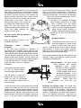
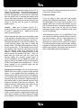
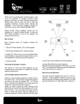
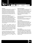
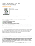
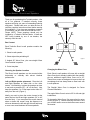
Pantent No. US 7,543,681 B2
User Manual - Ghost In-wall Speakers
Thank you for purchasing this TruAudio product. Like
all of our products, if installed correctly, these
speakers will bring you years of outstanding listening
enjoyment. Please make sure you take the time to
read the complete instruction manual before starting
the installation. If you have any questions, concerns
or comments, call our main office at 888-858-1555.
Please NOTE: These speakers should only be
installed by a TruAudio Certified Dealer. If these are
NOT being installed by one of our dealers, the
warranty could be void.
GPW-6
GPW-8
CENTER
25º
25º
Box Content
Each TruAudio Ghost In-wall speaker contains the
following:
1. Ghost In-wall speaker
2. Ghost-style white paintable grill
25º
3. Angled 25° Wave Cone, plus one straight Wave
Cone installed in speaker
25º
Figure 1
4. Cutout template
Choosing the Speaker Location
Changing the Wave Cone
The Ghost In-wall speakers can be mounted either
horizontally or vertically with almost identical
performance.
Each Ghost in-wall speaker will come with a straight
Wave Cone that is already installed with the speaker,
plus an additional angled Wave Cone set at 25°.
These Wave cones are designed to improve the front
soundstage that has always been a draw back with
in-wall speakers.
Left and Right speaker placement: Place the Left
and Right speakers on either side on the video
screen. You should try to place the tweeters as close
to ear level as possible (36" - 44" off the floor). Also
keep the speakers 6 to 12 feet apart and at least 16"
away from the wall. (Figure 1)
Ideally you want to place the center channel at the
same level as the left and right speakers (36" to 44"
from the floor). If you must place the center channel
above or below the screen, keep the distance to a
minimum between the left and right this will help keep
a more even sound between the three speakers.
The Straight Wave Cone is designed for Center
Channel installation.
The angled Wave Cone is set at a 25° for left and right
installations.
To change the Wave Cone, first remove the four outer
screws (Figure 3). Before removing the Wave Cone
you will also need to remove the three screws around
the tweeter.
Now pull the tweeter off the Wave Cone and set to the
side, being very careful not to damage the tweeter.
Do not disconnect the wires on the tweeter. Remove
the Wave Cone from the front of the speaker and
replace it with the new Wave Cone. Secure the new
Wave Cone with the four screws and place the
tweeter back on the Cone. There are
different screw holes for the tweeter on
the angled and straight Wave Cones.
Make sure that the tweeter sits
properly into place with the tabs on the
Wave Cone before fastening the
tweeter screws. Figure 3
Be very careful with the tweeter to
avoid any damage!
Speaker Installation
Now the speaker is ready to be
installed into the wall.
Preparation
before
Speaker
Installation
If the home was pre-wired for speakers at
construction time, TruAudio rough-in kits nay have
been used prior to drywall at each speaker location.
(There should also be speaker cable at this location).
After the drywall is installed and the hole is cut, the
speaker is then easily installed. Once the hole is cut
in the drywall, the pre-wired speaker cable should be
in the wall near the hole. If rough-in speaker
rings were used, move on to “Speaker
Installation”.
If the speaker hole has not been
cut from the drywall please
read the following instructions:
Find the location to where the
speaker wire was pre-wired to.
Check the area for obstructions
such as plumbing, heating ducts or
electrical wiring.
Figure 2
cut a small hole in the center of your outline. This will
allow you to check for obstructions. If there are no
problems with your mounting location, proceed and
cutout the outlined hole. At this point, you should be
able to see or find the speaker cable. Pull the
cable through the hole.
If the wall is not insulated, we suggest
using TruAudio model FE-24, an in-wall
foam enclosure that will greatly
improve the speakers sound. Other
options for sound dampening material
would include typical insulation or
Dacron. If this material has a foil layer,
position the foil away from the speaker
magnet.
Figure 3
Locate the wood studs or joists nearest the desired
location and make sure they will not interfere with
speaker location. Use the supplied speaker cutout to
get the recommended dimension of the hole needed
for that particular speaker. Position the cutout in the
desired location and outline the speaker opening to
be cut. If you are not sure of possible obstructions,
These speakers are mono so you will
need two speakers for stereo sound,
one for the right channel and one for
the left. There should be a two conductor speaker
cable pre-wire to each of the speaker locations.
Make sure you find each of the speaker cables and
pull them though the cut speaker holes.
Remove the speaker from the box and inspect for any
damage. If there is any damage, contact TruAudio
immediately at 888-858-1555.
Backbox Option: The Ghost In-wall
series speakers offer optional
backboxes
(part
number
BB-GW6 for GPW-6 speakers,
or part number BB-GW8 for
GPW-8 speakers) that can be
purchased separately. If you
are using the backboxes, now is
the time to attach them to the
speakers.
Please follow the
instructions that come with the
backbox.
Preparing the speaker cable: You should have
located the speaker cable by now, so it’s time to prep
it for connection to the speaker. Strip back the
outside insulation so the individual conductors are
showing. Depending on the cable, there should be
two or four separate conductors. Strip back the
insulation on each conductor to show the bare copper
wire. We suggest stripping enough so that 3/8” of
copper wire is showing. Push down each post and
insert the speaker cable. The posts will be located on
the back of the speaker on the crossover. Make sure
that only BARE wire is touching the speaker post
once it slides back into place. All TruAudio products
feature gold push binding posts which are quick and
simple to use and also are great for conducting
speaker signal.
Caution: Make sure to observe polarity, R +
(positive) from the amp or volume control to speaker
R + and R – (negative) to R –. Make sure to do the
same for the left channel.
When connecting the other end of the speaker cable
to the amplifier or receiver make sure to observe the
same polarity as you did at the speaker connection.
To prepare the speaker for the actual installation, turn
all the mounting toggles (dog ears) in toward the
speaker frame. This will allow the speaker to easily fit
into the precut hole. Put the speaker into the hole
(the speaker cable should be connected) and make
sure the speaker cable stays connected to the
speaker. Carefully tuck the speaker cable up into the
hole as you put the speaker into place. Hold it in
place with one hand and with your other hand
carefully tighten the mounting screws evenly to
secure the speaker. As you tighten the screws, the
dog ears will flip into position to grip into the drywall.
DO NOT over tighten the mounting screws. This will
cause damage to the mounting toggle and the
speaker will not stay in place.
Adjust the Level Control: Some of the Ghost series
models offer level control to adjust the high and low
output. If your speaker offers this functionality, the
switches are located on the front face of the speaker.
You can adjust these controls to get more or less high
frequency and more or less bass. Adjust the switch to
each setting until you get the desired amount of high
frequency and then do the same for the bass. We
suggest starting at -3dB and then from there you can
increase or decrease the desired level.
The
adjustments are -6dB, -3dB and 0dB.
Grill installation: Remove the grill from the box and
install it onto the speaker. Align the grills edges to the
outer edge of speaker and allow magnets to attach
grill to speaker, then carefully push the grill on. Make
sure to check all the way around the grill to ensure its
sitting on the speaker evenly.
Painting the Grills
If you are going to paint your grills, we suggest
painting the grills before Installation. This is one of
the advantages of the Ghost series speakers - the
speaker itself does not need to be painted, only the
grill. The Ghost series is a frameless speaker and will
save time on labor since the grill can be painted
beforehand and be ready for installation at the same
time as the speakers.
When painting the grills, it is very IMPORTANT that
you remove the cloth-like material (Dacron) from the
grill before painting. Paint the grills lightly and be
careful not to clog the holes. Depending on the
thickness of the paint, you may want to thin it slightly.
This will help prevent clogging the grill holes. Another
suggestion is finding a spray paint that will match and
paint the grill with that. Do not paint the grill while it’s
still on the speaker, paint them separately.
GPW-6
GPW-8
Specs: In-Wall, 2 Way
Woofers: 6 1/2" White Polypropylene
Tweeters: 1” silk soft dome
Power: 5 - 100 watts
Impedance: 8 ohm
Frequency Range: 45 - 20kHz.
Sensitivity: 89dB (2.83 volts @ 1 meter)
EQ Adj: Tweeter & Woofer 0, -3, -6
Grill: Ghost Style, Frameless
Finish Dimensions: 12" 7/8 (326mm) H,
9 1/8" (233mm) W, 3 3/4" (96.5mm) D
Cutout Dimensions: 8" (203mm) H,
11 5/8” (295mm) W
Specs: In-Wall, 2 Way
Woofers: 8" White Polypropylene
Tweeters: 1” silk soft dome, swivel
Power: 5 - 125 watts
Impedance: 8 ohm
Frequency Range: 40 - 20kHz.
Sensitivity: 90dB (2.83 volts @ 1 meter)
EQ Adj: Tweeter & Woofer 0, -3, -6
Grill: Ghost Style, Frameless
Finish Dimensions: 14 5/8" (370mm) H,
10 3/8" (264mm) W, 3 7/8" (98.56mm) D
Cutout Dimensions: 9 1/4" (234mm) H,
13 3/8” (340mm) W
SoundVision Technologies dba TRUAUDIO
PRODUCT WARRANTY
All in-wall, in-ceiling, outdoor speakers, volume controls and freestanding loudspeakers have a limited lifetime warranty.
This warranty includes lifetime parts and repair labor on all components. Powered subwoofers and active electronics
have a one (1) year limited warranty. This warranty includes one (1) year parts and repair labor on all components.
TRUAUDIO’s obligation under these warrantees is limited to repairing or replacing any component found defective in
material or workmanship under normal conditions of use. These warrantees shall not apply to products which have
been abused, modified, disassembled, or repaired by anyone other than TRUAUDIO or one of its appointed service
centers. Products to be repaired under this warranty must be returned to the factory or designated service center with
all transportation and insurance charges pre-paid.
It is the policy of TRUAUDIO to continuously incorporate improvements into our products. All specifications are subject to change
without notice. If you have any questions regarding this or any other TRUAUDIO products, please call 1-888-858-1555, Monday –
Friday, 7:00 am – 6:00 pm MST.
TRUAUDIO Speaker Systems, St. George, Utah, 84790
Office: 435.986.1574 Fax: 435.251.9815