1
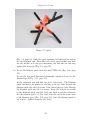
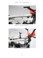
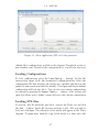
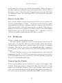
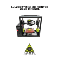
AO-101 User Manual
Aleph Objects, Inc.
TM
LulzBot
AO-101 User Manual
by Aleph Objects, Inc.
c 2012 Aleph Objects, Inc.
Copyright Permission is granted to copy, distribute and/or modify this document under the terms
of the Creative Commons Attribution-ShareAlike 3.0 Unported license (CC BY-SA 3.0).
Published by Aleph Objects, Inc., 123 SW 12th Street, Loveland, Colorado, 80537 USA.
For more information, call +1-970-377-1111 or go to www.LulzBot.com and
www.AlephObjects.com.
ISBN: 978-1-300-41435-3
20121120
Contents
WARNINGS
Safety Information
·
·
·
·
·
·
·
·
·
Read Me First! · · · · · · · · · · · · · · · · · · · · · · · · · · ·
Hazards and Warnings · · · · · · · · · · · · · · · · · · · · · · ·
1 Unpacking Your Printer ·
2 Setup Your Printer
3 3D
3.1
3.2
3.3
3.4
·
·
·
·
·
·
·
·
·
11
·
·
·
·
·
·
·
15
Printer Software
·
·
Software Overview · · · · · · ·
Slic3r · · · · · · · · · · · · · · ·
Printrun · · · · · · · · · · · · ·
CAD and 3D Modeling Software
4 Loading Filament
·
5 Your First 3D Print
5.1 Set Temperature ·
5.2 Load Filament · · ·
5.3 Home Printer · · ·
5.4 Z Print Height · · ·
5.5 Remove Part · · · ·
·
·
·
·
·
·
6 Maintaining Your
6.1 Overview · · · ·
6.2 Smooth Rods ·
6.3 PET Sheets · ·
6.4 Hobbed Bolt · ·
6.5 Software · · · ·
6.6 Belts · · · · · ·
6.7 Hot End · · · ·
·
·
·
·
·
·
·
·
·
·
·
·
·
· ·
· ·
· ·
· ·
·
·
·
·
·
·
·
·
·
·
·
·
·
·
·
·
·
·
·
·
·
·
·
·
·
·
·
·
·
·
·
·
·
·
·
·
·
· ·
· ·
· ·
· ·
· ·
·
·
·
·
·
·
·
·
·
·
·
·
·
·
·
·
·
·
·
·
·
3D Printer
· · · · · · · ·
· · · · · · · ·
· · · · · · · ·
· · · · · · · ·
· · · · · · · ·
· · · · · · · ·
· · · · · · · ·
·
·
·
·
·
·
·
·
·
·
·
·
·
·
·
·
·
·
·
·
·
·
·
·
·
·
·
·
·
·
· ·
· ·
· ·
· ·
· ·
· ·
· ·
·
·
·
·
·
·
·
·
·
·
·
·
·
·
·
·
·
·
·
·
·
·
·
·
·
·
·
·
·
·
·
·
·
·
iii
·
·
·
·
·
·
·
·
·
·
·
·
·
·
·
·
·
·
·
·
·
·
·
·
·
·
·
·
·
·
·
·
·
·
·
·
·
·
·
·
vii
viii
viii
·
·
·
·
·
·
·
·
·
·
·
·
·
·
·
·
·
·
·
·
·
·
·
·
·
·
·
·
·
·
·
·
·
·
·
·
·
·
·
·
·
·
·
·
·
·
·
·
·
·
·
·
·
·
·
·
·
·
·
·
·
·
·
·
·
·
·
·
·
·
·
·
·
·
·
·
·
·
·
·
·
·
·
·
25
26
26
28
32
35
·
·
·
·
·
·
37
38
38
39
41
42
·
·
·
·
·
·
·
43
44
44
44
44
45
45
45
·
CONTENTS
7 Advanced Usage ·
·
·
7.1 Intro · · · · · · · · · · · ·
7.2 Changing nozzles · · · · ·
7.3 ABS/Acetone Glue · · · ·
7.4 Using 1.75mm Filament · ·
·
·
·
·
·
·
·
·
·
·
·
·
·
·
· ·
· ·
· ·
· ·
·
·
·
·
·
· ·
· ·
· ·
· ·
·
·
·
·
·
·
·
·
·
·
·
·
·
·
·
8 Hardware and Software Source Code
·
·
·
·
·
·
·
·
·
·
·
·
·
·
·
·
·
·
·
·
·
·
·
·
·
·
·
·
·
·
·
·
·
47
48
48
49
49
53
9 3D Printer Support ·
·
·
·
·
·
·
·
·
9.1 LulzBot · · · · · · · · · · · · · · · · · · · · · · · · · · · ·
9.2 Community · · · · · · · · · · · · · · · · · · · · · · · · · ·
55
56
56
10 Contact Information
·
·
·
10.1 Support · · · · · · · · · · · · · · · ·
10.2 Sales · · · · · · · · · · · · · · · · · ·
10.3 Websites · · · · · · · · · · · · · · · ·
57
58
58
58
Index
·
·
·
·
·
·
·
iv
·
·
·
· · · · ·
· · · · ·
· · · · ·
·
·
·
·
·
· · · · · · ·
· · · · · · ·
· · · · · · ·
·
·
·
59
List of Figures
1.1
1.2
1.3
Orange Zip Ties · · · · · · · · · · · · · · · · · · · · · · · · · ·
Red Shipping Clamps · · · · · · · · · · · · · · · · · · · · · · ·
Using a wrench to pry off the shipping clamps · · · · · · · · ·
12
13
14
2.1
2.2
2.3
2.4
2.5
2.6
2.7
2.8
2.9
2.10
2.11
2.12
2.13
Axes movement directions · · · · · · · · ·
X and Z end stop locations · · · · · · · · ·
Y end stop location · · · · · · · · · · · · ·
Power supply and USB receptacles · · · ·
Power supply plug · · · · · · · · · · · · ·
The power supply and USB plugs correctly
Spool · · · · · · · · · · · · · · · · · · · · ·
Spool mount · · · · · · · · · · · · · · · · ·
Spool mounted · · · · · · · · · · · · · · ·
Filament Guide · · · · · · · · · · · · · · ·
Filament Guide Nuts · · · · · · · · · · · ·
Filament Guide Setting · · · · · · · · · · ·
SDRAMPS · · · · · · · · · · · · · · · · ·
· · · · · ·
· · · · · ·
· · · · · ·
· · · · · ·
· · · · · ·
plugged in
· · · · · ·
· · · · · ·
· · · · · ·
· · · · · ·
· · · · · ·
· · · · · ·
· · · · · ·
·
·
·
·
·
·
·
·
·
·
·
·
·
·
·
·
·
·
·
·
·
·
·
·
·
·
·
·
·
·
·
·
·
·
·
·
·
·
·
·
·
·
·
·
·
·
·
·
·
·
·
·
·
·
·
·
·
·
·
·
·
·
·
·
·
16
17
17
18
19
19
20
21
22
22
23
23
24
3.1
3.2
3.3
3.4
Slic3r application, STL to Gcode generator
Printrun application for 3D printer control
Printrun controls · · · · · · · · · · · · · ·
Printrun viewer · · · · · · · · · · · · · · ·
·
·
·
·
·
·
·
·
·
·
·
·
·
·
·
·
·
·
·
·
·
·
·
·
27
29
30
32
4.1
Filament spool direction · · · · · · · · · · · · · · · · · · · · ·
36
5.1
5.2
5.3
5.4
5.5
Extruder idler bolts
Extruder feed hole
Nozzle height · · ·
Z endstop trigger ·
First layer adhesion
·
·
·
·
·
·
·
·
·
·
·
·
·
·
·
·
·
·
·
·
·
·
·
·
·
·
·
·
·
·
·
·
·
·
·
v
·
·
·
·
·
·
·
·
·
·
·
·
·
·
·
·
·
·
·
·
·
·
·
·
·
·
·
·
·
·
·
·
·
·
·
·
·
·
·
·
·
·
·
·
·
·
·
·
·
·
·
·
·
·
·
·
·
·
·
·
·
·
·
·
·
·
·
·
·
·
·
·
·
·
·
·
·
·
·
·
·
·
·
·
·
·
·
·
·
·
·
·
·
·
·
·
·
·
·
·
·
·
·
·
·
38
39
40
40
41
WARNINGS
Safety Information
WARNING!
Read Me First!
READ THIS MANUAL COMPLETELY BEFORE UNPACKING AND
POWERING UP YOUR PRINTER.
Hazards and Warnings
Before you unpackage or use your printer: this 3D printer has motorized
and heated parts. When the printer is in operation always be aware of
possible hazards.
Electric Shock Hazard
Never touch the electronics board when the printer is powered on. Before
touching or removing any wires from the electronics board always power
down the printer and completely turn off and unplug the power supply and
allow the power supply to discharge for at least 1 minute.
Burn Hazard
Never touch the extruder nozzle or heater block without first turning off the
extruder heat and allowing it to completely cool down. The hot end can
take up to twenty minutes to completely cool. Also, never touch recently
extruded plastic. The plastic can stick to your skin and cause burns. Also
beware of the heated bed which can reach high temperatures capable of
causing burns.
Fire Hazard
Never place flammable materials or liquids on or near the printer when
powered or in operation. Liquid acetone and vapours are extremely
flammable.
Pinch Hazard
When the printer is in operation take care to never put your fingers in the
moving parts including the belts, pulleys, or gears. Also, tie back long hair
or clothing that can get caught in the moving parts of the printer.
viii
HAZARDS AND WARNINGS
Static Charge
Make sure to ground yourself before touching the printer, especially the
electronics. Electrostatic charge can burn up electronic components. To
ground yourself touch a grounded source.
Age Warning
For users under the age of 18, adult supervision is recommended. Beware
of choking hazards around small children.
ix
Unpacking Your Printer
Unpacking Your Printer
Figure 1.1: Orange Zip Ties
1. Remove the plastic bag containing instructions, cords, and small parts.
2. Remove the top foam padding.
3. Slowly remove the two smaller foam pads. One of these pads will
contain the plastic filament spool and plastic filament guide. The
other pad will contain the 5lb coil of ABS plastic filament. With the
two small foam pads remove and set aside these items.
4. Remove the white power supply box and the black tool bag. These
items are along opposite sides of the printer.
5. Grab the top of the wrapped printer on the top center where you
will feel two lengths of square aluminum tubing. Holding the top two
tubes, SLOWLY pull the printer upwards out of the box. The two
large side foam pads should fall off when the printer is out of the box.
6. Set you printer on a stable level surface.
7. Gently unwrap the pink ESD plastic covering the printer. Remove
the rolled sheet of PET tape from below the print bed. Gently lift
the printer to slide the plastic wrapping from under the printer.
12
LulzBot
TM
AO-101 User Manual
8. Find the item list attached to the plastic bag of parts. Before you
move on to setting up your printer make sure all of the items on the
list are in your package.
9. Using scissors or wire cutters, cut and remove the two ORANGE
plastic zip ties (Fig. 1.1, page 12) . One zip tie is located on the
bottom front of the printer on the print bed. The other zip tie is
wrapped around the extruder carriage and X axis. Make sure to not
cut any of the surrounding wires or belts.
Figure 1.2: Red Shipping Clamps
10. Remove the four red shipping clamps above and below the x-end motor
mount and idler (Fig. 1.2, page 13).
11. Loosen and remove the wing nut and screw on each of the four clamps.
Remove each of the four clamps by popping them off of the smooth
rod. Use a screwdriver or wrench to pry open and remove the clamps
if you have trouble removing them by hand (Fig. 1.3, page 14). Keep
the clamps and hardware for future use if you need to ship or transport
your printer.
13
Unpacking Your Printer
Figure 1.3: Using a wrench to pry off the shipping clamps
12. Remove the blue tape from the sides of the print surface. Make sure
to not remove the green PET tape on the glass print surface. The
PET tape helps keep the print attached to the print surface during
printing.
14
Setup Your Printer
Setup Your Printer
1. Your printer has been pre-calibrated and tested; however, after
unpacking you will need to double check that everything is in order
before you print.
2. You should set your printer on a stable, flat, and level surface large
enough for extra space around the printer. Make sure your printer
work space is clear of anything that could obstruct the movement of
the printer. Make sure there are no flammable fabrics or liquids near
the printer space. It is also best to not put your printer near a drafty
window or air conditioner vent.
3. Check that the three mechanical end stops are aligned to contact with
the respective ends. The mechanical end stops are small switches
located at the home point of each axis. (Fig. 2.1, page 16; Fig. 2.2,
page 17; Fig. 2.3, page 17).
Figure 2.1: Axes movement directions
4. Unwrap the power supply and USB cable.
MAKE SURE THE POWER SUPPLY IS COMPLETELY UNPLUGGED BEFORE MOVING ON TO THE NEXT STEP.
16
LulzBot
TM
AO-101 User Manual
Figure 2.2: X and Z end stop locations
Figure 2.3: Y end stop location
17
Setup Your Printer
5. Locate the power supply and USB receptacles along the bottom of
the RAMBo electronics enclosure (Fig. 2.4, page 18).
Figure 2.4: Power supply and USB receptacles
6. Plug in the USB cable, B plug (square plug) side, into the USB
receptacle on the printer electronics. Plug the other end of the USB
cable, A plug side, into your computer.
7. Make sure the printer power switch is turned off (the circle side should
be depressed). The LED on the power supply should not be lit. Plug
in the black power supply plug from the power supply into the power
supply receptacle on the printer. The power supply plug must be
aligned correctly with the flat side of the plug facing outwards from
the printer. (Fig. 2.5, page 19; Fig. 2.6, page 19). Now you can plug
in the AC power plug from the power supply into an AC power outlet.
8. Locate the plastic filament spool (Fig. 2.7, page 20).
9. Remove the large wing nut from the back of the spool. Take off one
washer leaving the other two on the spool mounting bolt. Now locate
the spool mount arm on the top right facing the rear of the printer
18
LulzBot
TM
AO-101 User Manual
Figure 2.5: Power supply plug
Figure 2.6: The power supply and USB plugs correctly plugged in
19
Setup Your Printer
Figure 2.7: Spool
(Fig. 2.8, page 21). Slide the spool mounting bolt through the hole in
the spool mount arm. From the back of the spool mount arm slide
the one washer on to the spool mounting bolt and turn on and snug
tighten the wing nut (Fig. 2.9, page 22).
10. Locate the filament guide with attached PTFE tube (Fig. 2.10, page
22).
Locate the top most horizontal aluminum extrusion closest to the
filament spool (Fig. 2.11, page 23).
In the extrusion you will find two loose t-slot nuts. The filament
guide attaches to the printer by screwing in the two bolts through the
filament guide into the t-slot nuts. First thread the two bolts through
the filament guide into the t-slot nuts. Leave the bolts loose enough
so the filament guide can slide back and forth across the extrusion.
Set the filament guide 1.5-2cm away from the end of the lower arms
of the filament spool (Fig. 2.12, page 23). Once the filament guide is
set in place, tighten down the two bolts.
20
LulzBot
TM
AO-101 User Manual
Figure 2.8: Spool mount
11. Insert the micro SD card into the micro SD card slot, found on the
top of the RAMBo electronics enclosure, shown in Figure 2.13, page
24.
21
Setup Your Printer
Figure 2.9: Spool mounted
Figure 2.10: Filament Guide
22
LulzBot
TM
AO-101 User Manual
Figure 2.11: Filament Guide Nuts
Figure 2.12: Filament Guide Setting
23
Setup Your Printer
Figure 2.13: SDRAMPS
24
3D Printer Software
3D Printer Software
3.1
Software Overview
Aleph Objects, Inc., the maker of the LulzBot AO-101 completely supports
free/libre hardware and software. Along with the AO-101 being a free/libre
hardware design, it has been tested to work with 100% free/libre software.
To operate your desktop 3D printer you will need to install a few software
packages onto your PC. You will need a 3D printer host, an .STL to .gcode
generator, and optional CAD or 3D modeling software.
All of the following free/libre software is available for GNU/Linux,
Windows, and Macintosh. However, we highly recommend using these
softwares on GNU/Linux.
The required software can be found in the Support/Downloads section
at www.LulzBot.com. You will also find instructions there for installing
each program onto your PC. Make sure to select the software version that
corresponds with the AO-101 3D printer and the operating system you are
using.
3.2
Slic3r
Website: www.slic3r.org
The Slic3r software is the first tool in the chain of 3D printing software
(Fig. 3.1, page 27).
Slic3r uses commonly used .STL (stereolithography) files to create .gcode
files. Gcode files contain instructions for the 3D printer on where, when,
and how fast to make movements. However, Gcode programming is not
very suitable for CAD and 3D design. This is where Slic3r and the .STL file
comes into use. The .STL file is a 3D model file that can be exported by all
common CAD and 3D modeling software. The Slic3r software then slices
the .STL 3D model into layers and print paths to create a 3D printable
.gcode file.
To launch Slic3r navigate to the Slic3r directory and launch the
slic3r.pl file. On GNU/Linux operating systems you may need to set the
slic3r.pl file as executable. On other operating systems it may be called
slic3r.exe.
Slic3r includes very simple settings that allow you to easily refine prints.
You can create multiple configurations for changing printer setups including
nozzle sizes and desired print resolution. For ease of use we have pre-
26
3.2. SLIC3R
Figure 3.1: Slic3r application, STL to Gcode generator
defined Slic3r configurations available in the Support/Downloads section at
www.LulzBot.com. Download the configurations to your Slic3r directory.
Loading Configurations
To load configurations press the Load Config... button. In the file
browser that opens, locate the downloaded configuration files. Select the
configuration file that matches the nozzle size currently installed on the
printer (0.5mm nozzle is installed by default). Press Open and the pre-defined
configuration will load into Slic3r. You can also save custom configurations
for yourself by pressing the Export Config... button. A file browser will
open that allows you to define a name and save your custom configuration.
Loading STL files
To load an .STL 3D model file into Slic3r, activate the Plater tab and click
the Add... button. In the file browser navigate to the .STL you wish to
load and click Open. The silhouette of the model will appear in the Plater
diagram. To print more than one copy of the model at a time select the
27
3D Printer Software
model name from the list and click the More button. With each press of
the More button an additional copy of the model will be added to Plater.
To remove a copy of the model select the model name again and click Less.
To completely remove the model from Plater select the model name and
click Delete.
Export Gcode files
Once you have finished setting your part(s) in Plater you can generate the
Gcode by clicking Export G-Code.... In the file browser navigate to where
you would like to save the .gcode file and list a name to save the file as.
Click Save and Slic3r will begin generating the .gcode file. When Slicer is
finished you will receive a prompt. If you have created a plate with multiple
model designs you can also use the Export STL... function to save an
.STL file for quickly reproducing the same plate of models.
3.3
Printrun
Website: github.com/kliment/Printrun
The host software, Printrun, is used to start up and control your 3D
printer (Fig. 3.2, page 29). The host controls include: setting the extruder
and print surface temperatures, manual control of each axis, and manual
extrusion. The host is also where you will push print files (.gcode) to
the 3D printer or load print files from the SD card for printing out model
designs.
To launch Printrun, navigate to the Printrun directory and launch the
pronterface.py file. On GNU/Linux operating systems you may need to
set the pronterface.py file as executable. On other operating systems the
file may be called pronterface.exe.
Connecting the Printer
To start up the printer, first you will need to connect to the printer with
Printrun. Make sure you have connected the USB cable from your PC to the
printer before launching Printrun. If not, close Printrun, connect the USB
cable, and relaunch Printrun. In the top left Port pull down menu select
the correct port for the printer (generally /dev/ACM0). On other operating
28
3.3. PRINTRUN
Figure 3.2: Printrun application for 3D printer control
systems the port may be named such as COM1 or tty.usbserial-USB-ID.
If you only have one printer connected there will only be one port available
to select. Make sure the port baud rate is set to 115200 in the pull down
menu to the right of the port selection. You can refresh the USB ports, by
clicking the Port button.
Now, to connect to the printer click the Connect button. In the text
output window you will see multiple return lines. If you see Printer is
now online you have succesfully connected to the printer. The printer
control buttons on the left will also darken and become clickable after
connecting. When you need to disconnect the printer simply press the
Disconnect button.
Printer Controls
All of the printer controls can be found on the left side of the Printrun
interface (Fig. 3.3, page 30). To set the hot end and print surface
temperature first click the Monitor Printer check box on. This will enable
the printer temparature bars and graph. The hot end and print surface
controls are labeled Heater and Bed. Select the temperature setting by
29
3D Printer Software
Figure 3.3: Printrun controls
using the pull down menu for pre-defined temperature settings. You can
also set custom temperature settings by typing into the temperature box.
To turn on the hot end and/or printer surface click the respective Set
button. The Set button will highlight orange when the temperature is set
to on for that component. When the hot end or print surface is set to on
you will see the temperature bar and graph display the set temperature and
the current temperature. When both components have reached the correct
temperature, the printer is ready for printing. Clicking the Off button will
turn off that component and highlight the Off button blue.
Below the temperature controls are the manual extrusion controls. There
you can manually extrude plastic through the hot end and retract the plastic
filament from the hot end. The Extrude button will feed the amount of
plastic, set to the right in mm, through the hot end. The rate at which the
plastic is fed is set below the extrusion length (mm/min). The Reverse
button will perform the opposite of Extrude, pulling the plastic filament
back out of the hot end.
The large pattern of buttons above the temperature controls are the
axes manual controls. These functions allows you to manually move each
of the three axes of the printer. The circular pattern of four quadrants
30
3.3. PRINTRUN
controls the X and Y axes. The top and bottom quadrants move the Y axis;
the top in the positive direction (forward) and the bottom in the negative
direction (back). The left and right quadrants move the X axis; the left in
the negative direction (left) and the right in the positive direction (right).
Each quadrant is split into four sections that control the length of
movement of 0.1mm, 1mm, 10mm, or 100mm. The innermost section moves
the axis 0.1mm with each section outwards a larger movement with the
outside section moving the axis 100mm.
The linear control bar to the right controls the Z axis. The Z axis is also
seperated into multiple movement lengths; 0.1mm, 1mm, and 10mm. The
upper three buttons move the Z axis up and away from the printer surface;
the three lower buttons move the Z axis closer to the print surface.
The four triangular buttons around the circular pattern are the axes
home buttons. Each home button will move that axis in the negative
direction until the end stop is activated. There is a home button for the X,
Y, and Z axes. There is also a white home all button that homes all of the
axes at once.
The Motors off button will deactivate all motors allowing all of the
axes to be moved by hand.
Caution: when homing, the axis will continue to move in the negative
direction until the end stop switch is activated. If the printer is ever
transported make sure the end stop switches are in the correct position
before printing. The end stops should be aligned so they will be activated
by the axes. If an axis has missed an end stop and is continuing to try to
move in the negative direction, immediately turn the power switch to the
off position. If a print file was running pause the print by clicking the Pause
button. Realign the end stop and try homing again.
Loading Print Files
To load a .gcode file into Printrun click the Load file button. Navigate
to the .gcode file in the file browser and click Open. You will now see a 2D
images of the first layer of your model design in the Gcode viewer (Fig. 3.4,
page 32). Click the Gcode viewer window to see a more detailed version
of the sliced model. In the pop-up Gcode viewer you can zoom in using
the mouse scroll wheel and flip through layers with the up and down arrow
keys. The lines shown in the Gcode viewer represent the path the extrusion
nozzle will follow to print the model.
31
3D Printer Software
Figure 3.4: Printrun viewer
For more information on using Printrun see the Printrun page in the
Support/Downloads section at www.LulzBot.com. Instructions for running
a print can be found in the Starting the First Print section in this manual.
3.4
CAD and 3D Modeling Software
Currently LulzBot is not distributing a CAD or 3D modeling software
package. However, there are multiple free/libre software packages available.
Other common non-free CAD and 3D modeling software are also capable of
exporting the required .STL files.
On some CAD and 3D modeling software you will need to select
millimeters as the output unit. If possible it is best to build your 3D
design in metric units rather than emperial units. Slic3r requires .STL files
sized in millimeters. If an .STL with inches as units is loaded into the Slic3r,
the model will be scaled much smaller than expected. The software listed
below outputs millimeters as the unit by default.
32
3.4. CAD AND 3D MODELING SOFTWARE
FreeCAD
Website: free-cad.sourceforge.net
Although still in development, FreeCAD is a great free/libre CAD
application. Containing a full GUI for building CAD models, FreeCAD is
capable of creating simple to complex designs. STL files can also easily be
exported for use with 3D printing. FreeCAD is available for GNU/Linux,
Windows, and Mac. The latest development version is recommended.
OpenSCAD
Website: openscad.org
OpenSCAD is another free/libre CAD software; however, different than
FreeCAD, it is script based. Rather than using a GUI to generate CAD
designs, OpenSCAD CAD designs are created using script based renderings.
Users with programming experience would find this very useful. Also,
OpenSCAD uses a simple script language that is easy to learn for users
with little or no programming experience.
Blender
Website: blender.org
The most widely used Free/Libre 3D modeling software, Blender is well
documented with tutorials available on the Blender.org website. Numerous
video tutorials can be also found online.
33
Loading Filament
Loading Filament
Figure 4.1: Filament spool direction
1. Loosen the three wing nuts on the upper arms of the filament spool.
2. Turn the upper arms 90 degrees upwards away from the printer.
3. Remove the 5lb coil of filament from the plastic packaging, leaving
the twist ties on.
4. Slide the coil over the spool upper arms. Make sure the filament coil
direction is counter clock wise (from the rear of the printer) when
placing the coil on to the spool (Fig. 4.1, page 36).
5. Lower the three upper arms and re-tighten the wing nuts.
6. The twist ties can now be removed. Keep the twist ties for future
use if you ever need to remove the filament to change to a different
filament.
7. Feed the end of the filament through the filament feed tube.
8. If it is loose, slide the opposite end of the filament through one of the
holes in hub of the filament spool. This will keep the filament from
unwinding from the spool.
36
Your First 3D Print
Your First 3D Print
5.1
Set Temperature
Make sure to first read the instructions for using the Printrun software.
Connect to the printer as described in the Printrun software section (page
28). Set the hot end and print surface for ABS plastic and turn both on.
The temperature settings should be set at 230◦ C for the hot end and 100◦ C
for print surface. If you have not already, make sure the axes end stops
are aligned to be triggered when each axis homes. Click the Motors Off
button.
5.2
Load Filament
Once the hotend is heated to the correct temperature you will now need to
load the plastic filament into the extruder. Loosen the two idler bolts (turn
the black plastic knobs by hand) to take pressure off of the idler springs
(Fig. 5.1, page 38). Pull both idler screws upwards to release the idler.
Figure 5.1: Extruder idler bolts
The idler can be turned downwards allowing access to the hobbed bolt and
filament feed hole. Feed the end of the plastic filament into the filament
38
5.3. HOME PRINTER
feed hole (Fig. 5.2, page 39). Now you can push the filament through the
Figure 5.2: Extruder feed hole
extruder by slowly pushing the filament down into the hot end.
Once the filament extrudes a small amount out of the nozzle raise the
idler and slide the two idler bolts and springs back into place. Tighten
the two idler bolts so that the knobs are distanced 20mm away from the
extruder body. Now use the Extrude button in Printrun to test that the
extruder is working properly.
5.3
Home Printer
Use the home buttons to home the X axis and then the Y axis. Next home
the Z axis. When the Z axis is at home the nozzle tip should be sitting
right against the glass (Fig. 5.3, page 40). The image to the right, in figure
5.3, is the correct nozzle height. The nozzle should not be pushing down on
the print surface. To lower or raise the Z home height adjust the Z end stop
trigger. The end stop trigger is on the far left of the printer near the print
surface (Fig. 5.4, page 40). The end stop trigger can be lowered by turning
clockwise and raised by turning counter-clockwise. Once you have homed
39
Your First 3D Print
Figure 5.3: Nozzle height
Figure 5.4: Z endstop trigger
40
5.4. Z PRINT HEIGHT
the axes and the hotend and bed have reached the correct temperature it is
time to print!
5.4
Z Print Height
Load the bedcalib.gco file.
This file can be found at:
http://download.lulzbot.com/AO-101/objects/calibration/bedcalib.gco
The .gcode pattern should appear in the Printrun G-Code viewer. Press
the Print button to begin the print. When the print starts make sure the
first layer is not printing too close or too far from the print bed. Note Figure
5.5, page 41, as an example of a good first layer adhesion. From left to right:
Figure 5.5: First layer adhesion
very low, low, perfect, high, very high. If the first layer is too high or low
you can pause the print by pressing the Pause button. Adjust the Z end
stop trigger. After making adjustments you can home the axes and press
Restart to restart the print.
41
Your First 3D Print
5.5
Remove Part
After the part is finished printing, the heated bed will automatically cool
down to 60◦ C. If you are printing PLA you will need to turn the heated
bed off. Once the bed cools you can you pop the finished part off of the
printed surface. To remove the printed part, use the clam knife included in
your printer kit. Leather gloves are suggested to protect your hands from
the clam knife blade. It is also safe practice to not place your hand behind
the direction you are pushing the clam knife. Using the side of the clam
knife blade pry up one side of the printed part. If your part is large you
may need to pry at multiple points to pop the part off of the print surface.
When removing parts take caution to not damage the PET film. If the film
is cut or ripped it will peel from the glass and need to be replaced. Make
sure to reset the heated bed to the correct temperature and allow it to heat
up to the needed temperature before starting the next print.
42
Maintaining Your 3D Printer
Maintaining Your 3D Printer
6.1
Overview
There is little maintenance needed in keeping your AO-101 3D printer
running. Depending on your rate of use you will want to perform a quick
check of your printer every 2-4 weeks. The following maintenance guide
lines will keep your printer printing quality parts.
6.2
Smooth Rods
Wipe the smooth steel rods with a clean rag or paper towel. The linear
bushings leave a solid lubricant that builds up over time. If you begin
hearing squeaking noises while the printer is printing, this is likely a sign
that the smooth rods need to be cleaned. NOTE: never apply any lubricant
to the smooth rods; the bushings are self lubricating.
6.3
PET Sheets
After repeated use, the PET sheet print surface will begin to wear. To
replace the PET print surface, remove the glass sheet from the printer. Peel
off the worn PET sheet from the glass sheet. If there is any glue or plastic
residue left on the glass surface, clean it with acetone or an alcohol based
glass cleaner. Using the green PET sheet from the printer kit lay down
the PET sheet onto the glass sheet. Use a credit card or driver’s license
to smooth down and push out any trapped bubbles under the sheet. For
additional replacement PET sheets visit the LulzBot.com store.
6.4
Hobbed Bolt
The plastic filament is pulled through the extruder by a hobbed bolt. After
repeated use, the teeth of the hobbed bolt can become filled with plastic.
Using the brush or pick from the printer kit clean out the hobbed bolt
teeth. If an extruder jam ever occurs, remove the plastic filament from the
extruder and clean out the hobbed bolt.
44
6.5. SOFTWARE
6.5
Software
Every quarter LulzBot will release new stable version of the software. It
is best to update the software every time a new version is released. The
software is as important in printing quality parts as the hardware. Each
quarterly software update can bring advances in print quality. The files
are available at http://download.lulzbot.com/AO-101/ . You can also
updated software versions in the Support/Downloads section of LulzBot.com.
6.6
Belts
Periodically you will need to retighten the belts on the AO-101 3D printer.
For the X axis, using the 2.5mm hex driver, loosen one of the belt clamps.
The belts clamps are located on the X axis carriage. To loosen the belt
clamp, loosen the M3 screws on each side of the clamp. Using the needle
nose pliers, pull the belt tight. While holding the belt tight, tighten down
both M3 screws. Y axis belt can be tightened using the Y idler tensioner.
Located on the lower front of the printer, the Y idler tensioner has an
adjustable bolt at the top of the tensioner. Turn the bolt clockwise to push
the top of the Y idler tensioner away from the aluminum frame and tighten
the belt.
6.7
Hot End
The hot end should be kept clean of extruded plastic by removing melted
plastic strands with the tweezers. If melted plastic builds up on the hot end
nozzle it can be cleaned with a paper towel soaked with acetone. Make sure
the hot end is completely cool before attemping to clean the nozzle with
acetone.
45
Advanced Usage
Advanced Usage
7.1
Intro
After becoming fimiliar with printing with the AO-101 3D printer with the
default settings there are a few advanced techniques that may help in getting
better and more consistent prints. Some of this instructions include items
and materials not included with the AO-101. With any of these additional
items or materials, follow safety and usage guidelines as instructed by the
manufacturer.
7.2
Changing nozzles
To achieve higher resolution parts you can change to a smaller sized nozzle,
included in the printer kit. Using the 0.25mm or 0.35mm nozzles you can
print at smaller layer heights to create smoother parts.
In most cases the nozzle is best changed when the hot end is completely
cool. NEVER try to remove the nozzle when the hot end is at extrusion
temperature. At higher temperatures the threaded extension expands in
the nozzle causing the nozzle to bind if turned.
To change the nozzle you will need the 18mm and 13mm wrench from
the printer tool kit. Slide the 18mm wrench onto the rectangular aluminum
heater block.
Using the 13mm wrench turn the nozzle counter clock-wise. Make sure
the nozzle is turning off of the threaded aluminum extension that runs up
through the heater block. Do not allow the heater block to turn. This can
put strain on and possibly damage the wiring. If the threaded aluminum
extension is turning with the nozzle, retighten the nozzle until it touches
against the heater block again.
To loosen a stuck nozzle off of the threaded extension, heat the hot end
to 90-100◦ C. This will soften the plastic inside the hot end and allow the
nozzle to be turned off of the threaded extension. Take care when removing
the nozzle while the hot end is hot. Wear leather gloves or use a towel to
turn the nozzle off of the hot end.
Once you have removed the nozzle you can then thread on the other
nozzle size you would like to use. Make sure the nozzle has threaded correctly
onto the threaded extension before trying to turn it with the wrench. Turn
the nozzle clock-wise until it tightens against the heater block.
48
7.3. ABS/ACETONE GLUE
After installing the new nozzle you may need to adjust your Z home
trigger setting before printing again. Refer to the Printing Your First Print
section (page 37) for calibrating the Z home trigger setting.
If you will be changing nozzles frequently we suggest reapplying a small
amount of high temperate anti-seize to the inside threads of the nozzles.
You will need an anti-seize capable of temperature of at least 250◦ C.
7.3
ABS/Acetone Glue
Acetone is not included or required with the AO-101 3D printer. An acetone
safety label is included for the HDPE bottle.
Acetone can cause skin irration when prolonged skin contact occurs. It
is recommended to use acetone safe gloves when applying the ABS/acetone
glue. Use the ABS/acetone glue in a well ventilated space. Leave the
mixture bottle closed except when applying a small amount to the wiping
towel. Acetone liquid and vapours are highly flammable. Keep acetone
away from open flames and high temperature sources, including the 3D
printer. Read the warnings label on your purchased acetone packaging for
additional warnings.
You may find that during printing, printed parts lift off of the print
surface on the corners. If you are seeing this problem you can make an
ABS/acetone glue to apply to the print surface. Using the HDPE acetone
safe bottle included in the printer kit, fill the bottle 3/4 full with acetone.
Now cut eight, 75mm lengths of ABS filament and put them in the bottle
with the acetone. Allow the ABS filament to dissolve for 2 hours.
To apply the acetone/ABS mixture put a small amount onto a paper
towel. Now, rub the towel onto the PET print surface to apply a thin layer
of ABS. Generally only one thin layer of the acetone/ABS solution is needed.
However, if needed you can apply multiple coats.
7.4
Using 1.75mm Filament
This procedure is highly advanced and involves disassembling parts of the
printer, including the hot end. We recommend using 3mm plastic filament
as we have yet to see major advantages to using 1.75mm filament. If you
would still like to use 1.75mm filament make sure to follow the instructions
49
Advanced Usage
carefully. If the instructions are not followed correctly you will run the risk
of damaging the printer and possibly voiding your warranty.
The AO-101 3D printer is set up to use 3mm plastic filament by default.
Although we recommend using 3mm filament, the AO-101 is also capable
of printing 1.75mm filament. To print with 1.75mm filament you will need
to change the PTFE tube inside the Budaschnozzle hot end. Included in
the printer kit is a 25mm PTFE tube with a 1.8mm inside diameter.
To change out the PTFE tube:
1. Remove the plastic filament from the extruder if there is any currently
loaded.
2. Unwrap the black wiring wrapping leading from the extruder to the
electronics.
3. Using the Printrun manual controls, raise the Z axis to 80mm.
4. Using a 3mm hex driver loosen and remove the two 4mm screws from
the bottom of the extruder X axis carriage. This will allow you to lift
the extruder body off of the hot end and carriage. Set the extruder
body aside. Lift the hot end up and out of the X axis carriage.
5. The hot end now has to be partially disassembled to replace the PTFE
tube for 1.75mm filament. Along with the following instructions,
you can see an instructional video on how to replace the PTFE at
http://youtu.be/7ExD5lY4-pI.
6. Using the 2.5mm hex driver, remove the three 3mm screws from the
top of the hot end. Remove the printed mounting plate.
7. Note the path of the wires through the three strain relief slots in the
wooden top plate. Gently remove the wires from the strain relief slots.
Remove the top wooden plate.
8. With the top wooden plate removed the white PTFE tube should
now be visible. The PTFE tube is set through an aluminum heat sink.
Remove the heat sink from the hot end.
9. The PTFE can generally be pushed out of the aluminum heat sink by
hand. Although, you may need to use the 4mm hex driver to push
the PTFE tube through and out of the aluminum heat sink. Place
aside the PTFE tube for 3mm filament.
50
7.4. USING 1.75MM FILAMENT
10. Push the PTFE tube for 1.75mm filament through the aluminum heat
sink. The PTFE tube should be approximately centered in the heat
sink with equal links of the PTFE tube sticking out of the heat sink.
11. Replace the aluminum heat sink and PTFE tube back into the hot end.
Lightly push down on the PTFE tube to make sure it is completely
set into the hot end.
12. Replace the top wooden plate. Make sure to line up the strain relief
slots on the side of the wires.
13. Place the printed mounting bracket on top. Screw in and lightly
tighten the three 3mm screws through the mounting bracket and top
wooden plate. Do not overtighten these screws as you can crack the
wooden plates.
14. Wrap the wires through the strain relief slots in the correct path of
all four wires, snaking through each slot together.
15. Place the hot end back down into the X axis carriage. Make sure the
wires are facing the rear of the printer
16. Place the extruder body back on top of the hot end and X axis carriage.
Line up the two mounting holes. Push the two 4mm screws through
the bottom of the X carriage, through the hot end, and into the
extruder body. Thread the screws using the 3mm hex driver but leave
loose for now.
17. Rewrap the wire wrap around the extruder and hot end wires.
18. Finally, push 1.75mm filament through the extruder and into the hot
end. This will align the filament travel space. Tighten the two 4mm
screws from the bottom of the X axis carriage.
Before printing with 1.75mm filament, make sure to make the needed
changes in Slic3r for 1.75mm filament. You will need to reslice any previously
sliced files with the new settings for 1.75mm filament.
51
Hardware and Software Source Code
Hardware and Software Source Code
TM
The LulzBot AO-101 3D printer is a free/libre hardware design. All
of the source files are available at http://download.lulzbot.com/AO-101
including:
• The latest version of this document, with LATEX source code.
• 3D models and print files for all of the printed parts in .stl, .gcode,
and other original source files.
• 3D calibration objects and random novelties.
• Production file for calculating large print runs.
• Design files for all electronics and machined parts.
– PCB Heatbed
– RAMBo
– SDRAMPS
– Various spec sheets
• Bill of materials including every part needed to build the printer.
– AO-101
– Budaschnozzle
• Drawings of components.
– Aluminum extrusions
– Budaschnozzle
– Y plates
• Software binaries and source code for GNU/Linux and others. Also
includes known good configuration files.
– Slic3r
– Printrun
– Marlin
54
3D Printer Support
3D Printer Support
9.1
LulzBot
For technical support for your AO-101 3D printer please e-mail our support
team at [email protected]. Please completely read this manual
before contacting for support questions or help. The latest version of
this information guide is also available at http://download.lulzbot.com.
You can also find more information including images, videos, and updated
versions of this manual in the Support section of LulzBot.com.
9.2
Community
Community Support and Resources
• IRC chat rooms on the irc.freenode.net server.
– #reprap: Highly active community chat room where help can
easily be found
– #slic3r: Slic3r chat room where Slic3r developers and users can
give help
• RepRap.org forums: forums.reprap.org
56
Contact Information
Contact Information
10.1
Support
Email: [email protected]
Phone: +1-970-377-1111
10.2
Sales
Email: [email protected]
Phone: +1-970-377-1111
10.3
Websites
Aleph Objects, Inc., the makers of LulzBot 3D Printers:
www.AlephObjects.com
LulzBot 3D Printers and parts:
www.LulzBot.com
58
Index
Symbols
1.75mm filament, 49
E
electronics, viii, 54
electronics receptacles, 16
end stops, 16, 31
extrude, 30
extruder, viii, 28
extruder jam, 44
extrusion, 28
A
ABS, 49
acetone, 44, 45, 49
advanced techniques, 48
aluminum extrusions, 54
anti-seize, 49
axes, 30
F
feed tube, 36
filament, 38
filament guide, 12
filament spool, 12, 36
foam padding, 12
forums, 56
FreeCAD, 33
Freenode, 56
B
baud rate, 28
belts, 45
bill of materials, 54
Blender, 33
blue tape, 13
bottle, 49
Budaschnozzle, 54
burns, viii
bushings, 44
G
gcode, 26, 28, 31, 54
glass, 44
GNU/Linux, 26, 28, 33
C
CAD, 26, 32
calibration, 54
community support, 56
configuration, 27
connecting, 28
H
hardware, 54
hazards, viii
heater block, viii, 48
high resolution, 48
hobbed bolt, 44
D
download, 26, 45, 54
59
INDEX
home, 31
hot end, 29, 30, 38, 45, 48
I
idler, 13
instructions, 12
IRC, 56
L
latex, 54
load files, 31
lubricant, 44
M
Macintosh, 26, 33
maintainence, 44
manual controls, 30
Marlin, 54
motors, 31
N
novelties, 54
nozzle, 48
O
OpenSCAD, 33
operating system, 26
P
PCB Heatbed, 54
PET sheet, 13, 44, 49
plater, 27
pliers, 18
port, 28
power supply, viii, 12, 16
power switch, 18
printed parts, 54
Printrun, 28, 29, 31, 54
pronterface, 28
PTFE tube, 20, 49
R
RAMBo, 18, 54
RepRap, 56
resolution, 26
S
SD card, 28
SDRAMPS, 54
shipping clamps, 13
Slic3r, 26, 54
smooth rods, 44
software, 26, 32, 45, 54
source code, 54
spool, 18, 36
static, ix
STL, 26, 27, 32, 54
T
technical support, 56
temperature, viii, 28, 30, 38
threaded extension, 48
tool bag, 12
U
USB cable, 16, 28
W
warnings, viii
warping, 49
Windows, 26, 33
wing nuts, 36
wires, viii
wrench, 18, 48
X
X axis, 30
x-end motor mount, 13
Y
Y axis, 30
60
INDEX
y plates, 54
Z
Z axis, 30
61
Colophon
Created with 100% Free/Libre Software
GNU/Linux
EX Memoir
LAT