1
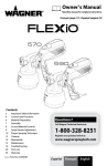
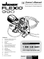
Owner’s Manual Read this manual for complete instructions Français (page 21) / Español (página 41) Contents 2 4 5 6 7 8 9 10 12 16 17 18 61 68 Important Safety Information Controls and Functions Overview Setup Preparing to Spray Power and Material Controls Spray Pattern Adjustment Proper Spraying Technique Cleanup Maintenance Troubleshooting Control Finish Nozzle Setup Parts List Warranty 0215 • Form No. 0529403C Questions? Call Wagner Technical Service at: 1-800-328-8251 Register your product online at: www.wagnerspraytech.com Español Français English Important Safety Information Read all safety information before operating the equipment. Save these instructions. Indicates a hazardous situation which, if not avoided, could result in death or serious injury. To reduce the risks of fire or explosion, electrical shock and the injury to persons, read and understand all instructions included in this manual. Be familiar with the controls and proper usage of the equipment. Grounding Instructions This product must be grounded. In the event of an electrical short circuit, grounding reduces the risk of electric shock by providing an escape wire for the electric current. This product is equipped with a cord having a grounding wire with an appropriate grounding plug. The plug must be plugged into an outlet that is properly installed and grounded in accordance with all local codes and ordinances. warning - Improper installation of the grounding plug can result in a risk of electric shock. If repair or replacement of the cord or plug is necessary, do not connect the green grounding wire to either flat blade terminal. The wire with insulation having a green outer surface with or without yellow stripes is the grounding wire and must be connected to the grounding pin. Check with a qualified electrician or serviceman if the grounding instructions are not completely understood, or if you are in doubt as to whether the product is properly grounded. Do not modify the plug provided. If the plug will not fit the outlet, have the proper outlet installed by a qualified electrician. This product is for use on a nominal 120 volt circuit and has a grounding plug that looks like the plug illustrated below. Make sure that the product is connected to an outlet having the same configuration as the plug. No adapter should be used with this product. WARNING - To reduce the risk of fire or explosion: 1. Do not spray flammable or combustible materials near an open flame, pilot lights or sources of ignition such as hot objects, cigarettes, motors, electrical equipment and electrical appliances. Avoid creating sparks from connecting and disconnecting power cords. 2. For use with only water-based or mineral spirit-type materials with a minimum flash point of 100º F (38ºC) — Do not spray or clean with liquids having a flash point of less than 100º F (38ºC). Flash point is the temperature at which a fluid can produce enough vapor to ignite. 3. Verify that all containers and collection systems are grounded to prevent static discharge. 4. Connect to a grounded outlet and use grounded extension cords (electric models only). Do not use a 3 to 2 adapter. 5. Keep spray area well ventilated. Keep a good supply of fresh air moving through the area to keep the air within the spray area free from accumulation of flammable vapors. 6. Do not smoke in the spray area. 7. Do not operate light switches, engines, or similar spark producing products in the spray area. 8. Keep area clean and free of paint or solvent containers, rags, and other flammable materials. 9. Know the contents of the paint and solvents being sprayed. Read all Material Safety Data Sheets (MSDS) and container labels provided with the paints and solvents. Follow the paint and solvent manufacture’s safety instructions. 10. Fire extinguisher equipment shall be present and working. Grounded Outlet Grounding Pin Cover for grounded outlet box 2 English © Wagner Spray Tech - All Rights Reserved Important Safety Information WARNING - To reduce the risk of injury: 1. Always wear appropriate gloves, eye protection, clothing and a respirator or mask when painting. Hazardous vapors – Paints, solvents, insecticides, and other materials can be harmful if inhaled or come in contact with body. Vapors can cause severe nausea, fainting or poisoning. 2. Do not operate or spray near children. Keep children away from equipment at all times. 3. Do not overreach or stand on an unstable support. Keep effective footing and balance at all times. 4. Stay alert and watch what you are doing. 5. Do not operate the unit when fatigued or under the influence of drugs or alcohol. 6. Never aim spray gun at any part of the body. 7. Follow all appropriate local, state, and national codes governing ventilation, fire prevention, and operation. 8. The United States Government Safety Standards have been adopted under the Occupational Safety and Health Act (OSHA). These standards, particularly part 1910 of the General Standards and part 1926 of the Construction Standards should be consulted. 9. Use only manufacturer authorized parts. User assumes all risks and liabilities when using parts that do not meet the minimum specifications and safety devices of the turbine manufacturer. 10. Power cord must be connected to a grounded circuit. 11. Do not spray outdoors on windy days. WARNING - To reduce the risk of electric shock: 1. Always remove turbine before cleaning. 2. Power cord must be connected to a grounded circuit. 3. Never submerge electrical parts in liquids. 4. Never expose the equipment to rain. Store indoors. 5. Keep electrical cord plug and spray gun trigger free from paint and other liquids. Never hold the cord at plug connections to support the cord. Failure to observe may result in an electrical shock. 6. The electrical cord has been specially designed to safely carry the electrical load of this system. Do not use other non FLEXIO 990 HVLP turbines in conjunction with this unit. Important Electrical Information Use only a 3-wire extension cord that has a 3-blade grounding plug and a 3-slot receptacle that will accept the plug on the product. Make sure your extension cord is in good condition. When using an extension cord, be sure to use one heavy enough to carry the current your product will draw. An undersized cord will cause a drop in line voltage resulting in loss of power and overheating. A 14 gauge or 12 gauge, 25-foot 300V cord is recommended. If an extension cord is to be used outdoors, it must be marked with the suffix W-A after the cord type designation. For example, a designation of SJTW-A would indicate that the cord would be appropriate for outdoor use. IMPORTANT: Household use only. Intended for indoor/outdoor use ONLY with materials having flashpoint above 100ºF (38ºC). Thank you for your purchase! Thank you for purchasing the Wagner FLEXiO sprayer with best-in-class features that are designed for spraying residential paint, un-thinned, indoors or out. Only the FLEXiO sprayers have the power of the X-Boost® turbine and versatility of the iSpray nozzle that will help you finish projects fast and professionally. They are easy to use right out of the box and with low overspray and less clogging you will enjoy the flexibility to tackle all the painting projects on your list. We appreciate your feedback, so please visit our website and write a review on the FLEXiO handheld sprayer so we can continue to learn and improve our products. Just click on www.wagnerflexio.com If you have any questions about your FLEXiO sprayer, please call Technical Service at 1-800-328-8251. See www.wagnerspraytech.com in the “Contact Us” section for Technical Service hours. © Wagner Spray Tech - All Rights Reserved English 3 Controls and Functions Suction tube Filter housing (both sides) Suction tube holder / paint can X-Boost™ turbine attachment bracket X-Boost™ power dial Material flow control ON / OFF switch Belt clip attachment Spray nozzle Adjustment ring Spray width lever Turbine power cord To p ai hos nt e 2-Stage trigger Paint hose Fluid pump To pow turbin e er (14 cord .5 ft ) Spray Process With this spray system, the fluid pump delivers material through the paint hose to the spray nozzle. At the spray nozzle, the material is atomized (sprayed) by the air provided by the turbine. For a more detailed outline of the sprayer controls, refer to pages 8-9. Fluid Pump: ON/OFF Switch: The fluid pump delivers material from the material container to the spray nozzle via the spray hose. The ON/OFF switch on the fluid pump turns power to the system on and off. X-Boost Turbine: The X-Boost Turbine supplies the air that forces the material out of the spray nozzle. When plugged in, power to the turbine is provided by pulling the trigger. 4 English © Wagner Spray Tech - All Rights Reserved Overview Note: Follow the steps below to unpackage your sprayer and prepare the system. 1. Pull the suction tube (a) from the suction tube holder. Pull the yellow handle (b) away from the pump and unhook it. Pull it backwards over the pump to free the clear paint hose (c) and electrical cable from the suction tube holder. 2. Once the clear paint hose and electrical cable are removed from the suction tube holder, replace the yellow handle (d) back into the pump as shown, just above the suction tube holder. 3. On the other side of the pump, fold up the black bracket (e) and remove the spray gun from the pump. Completely unwind the paint hose. Nozzle Selection 1 b 1 a c 2 2 d Note: Your unit includes two spray nozzles. See below to determine the correct nozzle for your spraying project. • Direct Feed iSpray Nozzle - used for broad surface coating. Designed for spraying thicker materials, such as latex paints and stains. Spraying with this nozzle will leave a slightly coarser finish that is between a roller and fine-finish sprayer. 3 e • Control Finish Nozzle - used for small projects and fine finishing. Designed for spraying thinner materials, such as water- and oil-based stains and thinned paints. The Control Finish Nozzle leaves a smooth finish. If planning to use the Control Finish Nozzle, refer to pages 18-21 for setup and use instructions. Note: These two spray nozzles have different spray pattern / width controls. Make sure to familiarize yourself with the controls on each spray nozzle. See the “Controls” section, page 8-9. © Wagner Spray Tech. - All Rights Reserved English 5 Setup Before you begin Watch Setup: www.flexio990/setup 1 NEVER point the spray gun at any part of the body. IMPORTANT: Make sure the power cord is unplugged. Setup Note: Make sure the system is placed in a level, clean surface. Follow these instructions for both one-gallon and five-gallon containers. 1. Lift up the suction tube holder as far as it will go. 2. Position the material container next to the pump assembly as shown. The container handle (a) should be vertical and placed in between the two suction tube guides. Slide the suction tube holder (b) down until it touches the top of the material container. The container is now secured to the pump and the entire unit can be carried by the container handle. 2 b a important: The container handle must be placed between the two suction tube guides, or the container will tip when carried due to the added weight of the pump assembly. 3. Place the suction tube back into position in the suction tube guide. Make sure the tube reaches the bottom of the material container. Note: If working on a ladder, use the belt clip. This accessory provides 1) a place to hook the sprayer to free your hands and 2) a place to attach the spray hose to reduce the pull on your arm. 3 4. Guide the cord (c) behind the tab (d) on the clip (the paint hose does not need to be secured, as it is attached to the cord). The cord should be attached near the turbine plug (e). 5. Attach the belt clip to yourself (it is recommended that it be secured to waistband of your pants). 6. If necessary, hook the spray gun into the belt clip with the attachment (f). 4 5 6 e 6 f d c English © Wagner Spray Tech. - All Rights Reserved Preparing to Spray Note: Before spraying, you will need to prime the system (deliver material from the container to the spray nozzle via the paint hose). Follow the steps below. 1 You Will Need: • Waste bucket • Drop cloths to protect floors and furnishings from overspray Preparing to Spray 1. Point the spray nozzle into the side of an empty waste container. Squeeze and hold the trigger for the next steps. 2 Note: Point the sprayer to the side of the waste container to minimize overspray. 2. Turn the ON/OFF switch to ON. Material will begin to flow from the container into the paint hose. Air will blow from the spray nozzle. 3. Continue to squeeze the trigger until the material is flowing freely from the spray gun. The system is now primed and you are ready to spray. Note: If the sprayer has been used before, some cleaning solution may be left in the paint hose from previous cleanings. Squeeze the trigger until all air and cleaning solution is purged from the hose and material is spraying from the nozzle. ON 3 Note: The fluid pump will cycle ON and OFF while spraying to regulate pressure. This is normal. © Wagner Spray Tech - All Rights Reserved English 7 Power and Material Controls Watch Painting: www.flexio990/painting Material Flow Control Spray performance will depend upon a number of factors: material thickness, air power, spray pattern selected, and material flow. Testing different variations of the control settings will help you achieve the desired results. See descriptions and suggested Power and Material Settings Guide below to help with your project. The material flow control determines the amount of spray material that is sprayed from the spray gun. Set the material flow by turning the knob on the body of the spray nozzle (iSpray) or the knob on the back of the trigger (Control Finish). iSpray Control Finish X-Boost™ Power Dial The X-Boost™ power dial adjusts the level of air pressure produced by the turbine. The X-Boost™ power dial is factory-set at maximum out of the box. • A high air power level will result in faster coverage and a smoother finish with thicker materials. • Lowering the air power will result in larger drops of material being sprayed from the gun, and will create a slightly rougher finish. • For thicker materials, it is recommended that you start with the material flow setting (5) and then gradually increase the flow to suit your particular spraying needs. • For thinner materials, it is recommended that you start with a low material flow setting (1), and then gradually increase the flow to suit your particular spraying needs. • The higher the flow setting, the quicker you will have to work in order to avoid drips and sags in your spray pattern. + - Tip: The thicker the material you are spraying, the higher the turbine power you will need. Thick materials will spray on coarse and smooth out as it dries. Tip: For fine-finish work with thinner materials, you may want to decrease the air power. Spraying a thinner material at high air power will result in more overspray. Overspray is sprayed material that does not stick to the spray surface and bounces back. Tip: Spraying with the control set too high will result in a spray pattern that runs and sags (too much material). Tip: Spraying with the control set too low will result in a spray pattern that does not cover (not enough material). Tip: To ensure desired results are achieved with the controls, test your spray pattern on the spray poster or a scrap piece of wood or cardboard. Power and Material Settings Guide iSpray Nozzle Coating Control Finish Nozzle Material Flow Air Power Material Flow Air Power Transparent / semi-transparent stains, sealers 1-3 3-4 Med/Heavy min-3 Lacquers (water based) 1-4 3-4 Med/Heavy min-3 Solid stains 3-7 4-7 Med 4-7 Polyurethane 5-8 4-7 Med/Heavy 4-7 Oil enamels 9-10 6-9 Heavy 6-9 Latex paints plus primers, Latex paints 9-10 7-max Heavy* 7-max* Oil or latex primers 9-10 7-max Heavy* 7-max* * Thinning may be necessary to speed up spraying. 8 English © Wagner Spray Tech - All Rights Reserved Spray Pattern Adjustment Adjust Spray Shape - both nozzles Adjust Spray Width - iSpray only The spray pattern shape is adjusted by turning the adjustment ring to either the vertical or horizontal positions. The positions of the air cap and the corresponding spray pattern shapes are illustrated below. Test each pattern and use whichever pattern is suitable for your application. The spray width lever on the iSpray nozzle determines the width of the spray pattern. Spray width lever never trigger the gun while adjusting the ears on the air cap. NEVER point the spray gun at any part of the body. iSpray Wide pattern Control Finish Adjustment ring Air cap ears Narrow pattern = Horizontal= pattern = = Vertical pattern = = Round pattern* = = Use ‘up and down’ spraying motion For coating large surfaces Use higher air power Use higher material flow For coating smaller areas, corners and edges Use lower air power Use lower material flow Note: Make sure the width lever is firmly set in either one of these positions. If it is between positions, the spray pattern will be disrupted. Tips: Use ‘side to side’ spraying motion Use ‘up and down’ or ‘side to side’ spraying motion Use lower air power / material flow For coating smaller areas, corners and edges 1. Start with a fan pattern for painting trim work (1-5” width) and larger surfaces like doors and walls (>5” width). 2. Adjust Material & Air Flow settings as shown in chart based on coating, fan pattern width, and nozzle. 3. Fine tune the Material and Air Power settings to achieve the best results for your application. 4. Pull trigger slightly to start the turbine before pulling all the way to spray material. 5. Use narrow pattern for detailed work, touch up. 6. Recommended settings for Material and Air Power may change if the coating is thinned. IMPORTANT: When changing the spray pattern, = make sure the black retaining ring is not loosened. *Note: The air cap can be set diagonally on the Control Finish nozzle only. To achieve a round pattern with the iSpray nozzle, see the “Adjust Spray Width” section. © Wagner Spray Tech - All Rights Reserved English 9 Proper Spraying Technique The room you are spraying must be properly STOP masked in order to prevent overspray from covering woodwork, floors or furnishings. Make sure you have properly masked the room per the instructions on the enclosed “Taping Guide”. If spraying with an paint sprayer is new or unfamiliar to you, it is advisable to practice on a piece of scrap wood or cardboard before beginning on your intended workpiece and/or test with water. can get closer to the spraying surface. • Spray parallel to the surface with smooth passes at a consistent speed as illustrated below. Doing this will help avoid irregularities in the finish (i. e. runs and sags). Even coat throughout 6 to 8 inches Keep Container Filled! Periodically check the material container to make sure the suction tube and inlet filter is submerged in the material. If your spray job requires more than one container of material, it is recommended that the new container be poured into the container that is secured to the unit. This will keep the inlet filter submerged and prevent air from entering the system. If you accidentally run out of material, you will need to follow the “Preparing to Spray” instructions on page 7 to re-prime the system. Spray Poster A spray poster is included with your unit. The spray poster can be adhered to a spraying surface and can be used for practice. Follow the guidelines on the poster. Surface Preparation All objects to be sprayed should be thoroughly cleaned before spraying material on them. Areas not to be sprayed may, in certain cases, need to be masked or covered. Correct Keep stroke smooth and at an even speed • Always apply a thin coat of material on the first pass and allow to dry before applying a second, slightly heavier coat. • When spraying larger surfaces, overlap each spray pass by at least 50% This will ensure full coverage. • When spraying, always trigger the spray gun after spray pass has begun and release trigger before stopping the pass. Always keep the gun pointed squarely at the spray surface and overlap passes slightly to obtain the most consistent and professional finish possible. Light coat Heavy coat Light coat Incorrect Spray Area Preparation The spray area must be clean and free of dust in order to avoid blowing dust onto your freshly sprayed surface. How to Spray Properly It is important to keep your arm moving STOP whenever the gun is being triggered. If you pause or linger in one spot too long, too much material will be sprayed to the surface. Partially pulling the trigger will start STOP the turbine, but no material will spray until the trigger is pulled fully. It is recommended that the trigger first be pulled partially in order to start the turbine before a spray pass is made. • Position the spray gun perpendicular to and six (6) to eight (8) inches from the spray surface, depending upon the spray pattern size desired. With reduced material flow and air power, you 10 English Do not flex wrist while spraying. During a project, periodically wipe the STOP nozzle tip with a cloth to remove any dried paint. Note: When you quit spraying for any length of time, switch off the pump / unplug the sprayer. When you restart, wipe the nozzle with a damp cloth to remove any dried paint. © Wagner Spray Tech - All Rights Reserved Proper Spraying Technique Pattern Examples Use the images and guidelines below in order to assist you in achieving the desired spray pattern for your project. These are meant to be general starting points - you may have to slightly modify certain controls on the system in order to get the exact performance you need. Note: It is recommended that the trigger first be pulled partially in order to start the turbine before a spray pass is made. Small Surface Projects Generally, low material flow and air power are needed for spraying smaller surface areas, such as corners, lattice, or spindles. For this type of project, reduce power, material flow and switch to a narrow width when using the iSpray nozzle. The Control Finish Nozzle provides an even narrower pattern for smaller surface projects and fine finishing. Moving closer to the spray surface narrows the fan and moving farther away widens it. During a project, periodically wipe the STOP nozzle tip with a cloth to remove any = dried paint. Large Surface Projects OR Generally, high material flow and air power are needed for spraying large surface areas, such as walls and decks. The iSpray nozzle is ideal for these applications and is designed for broad coverage in either horizontal or vertical spraying. = = • If you feel the material is going on too thin, increase the material flow. • If you feel the material is going on too thick, decrease the material flow even further or move the spray gun further away from the surface. Note: If after following the guidelines on these two pages you are still not getting the spray performance you need, refer to the ‘Troubleshooting’ section on page 15. • The air cap position will determine the movement direction of the spray gun. Besides adjusting the controls, other factors that should be considered when spraying: • Distance from the spray object - if you are too far from the spraying surface, the material will go on too thin, and vice versa. • Material thickness - if the spray pattern runs and/or is too splotchy, the material may need to be thinned. Note: Only thin the material if absolutely necessary to improve spray performance. Optimal spray performance should be acheived simply by adjusting the various controls on the unit. If the material needs to be thinned, dilute the material in steps of 5% - 10% until the desired spray pattern is acheived. • Spray gun movement - moving the gun too quickly will cause the spray pattern to be too thin and excess overspray. Moving the gun too slowly will cause the spray pattern to be too coarse or thick. © Wagner Spray Tech - All Rights Reserved English 11 Cleanup Watch Cleanup: www.flexio990/cleanup Purging the Paint Hose Before you begin IMPORTANT: Make sure a drop cloth is placed underneath the pump and material container to catch any drips. Note: Follow the cleanup steps in this manual if you used the Direct Feed iSpray nozzle only. If you used the Control Finish nozzle, follow the cleaning instructions on pages 19-20 in this manual. 1 To Purge the Paint Hose 1. Turn the ON/OFF switch to OFF. Lift the suction tube holder up a few inches. Allow the suction tube to come up so that it is no longer submerged in the material, but leave it in place within the suction tube holder. 2. Push the tab below the trigger (a), twist and separate the nozzle from the turbine. Wipe the exterior of the nozzle until clean. Open the velcro strap at the paint hose and separate the power cord from the hose at about a length of 3 feet from the turbine. 2 a Do not submerge or allow the turbine to come into contact with any liquids. 3. Turn the material flow control knob to 12. Pull the trigger backwards and pull out the trigger stop (b). Note: The material flow control knob must be set to 12 in order for the trigger stop to move out. 3 4. Using the belt clip attachment, hook the nozzle onto the empty suction tube holder (the one that does not currently have the suction tube in it) as shown. The front of the nozzle should be pointing directly into the material container. 5. Turn the ON/OFF switch to ON. Allow the pump to run until all paint is purged from the spray hose. Turn the pump OFF. Leave the trigger stop in place for the next steps. 4 12 English b 5 © Wagner Spray Tech - All Rights Reserved Cleanup (continued) Flushing the Nozzle Before you begin 1 • If you sprayed using latex materials, you will need a 1- to 5-gallon container filled with warm, soapy water. • If you sprayed oil-based materials, you will need a bucket filled with approximately 1 quart of mineral spirits. Special cleanup instructions for use with flammable solvents (must have a flashpoint above 100ºF (38ºC): • • • • Always flush spray gun outside. Area must be free of flammable vapors. Cleaning area must be well-ventilated. Do not submerge turbine! To Flush the Direct Feed iSpray Nozzle 2 1. Remove the material container from the pump (you may have to lift up the suction tube holder to make room). 2. Replace the material container with a bucket of the appropriate cleaning solution (see “Before you begin”, above). Lower the suction tube holder and submerge the suction tube into the cleaning solution. cleaning solution Note: The spray nozzle should now be pointed directly into the container of cleaning solution. Turn the pump ON and allow cleaning solution to circulate for approximately 5 minutes. 3. After 5 minutes, while pump is running, remove suction tube from the cleaning solution and allow the solution to purge from the nozzle and paint hose. Turn the pump OFF. 4. Repeat steps 2 and 3 twice using new cleaning solution each time. At the end of the third flushing, remove the suction tube from the holder, and raise it up so it is vertical. This will allow all fluids to be purged. Keep the pump running for the next step. Note: The suction tube may no longer be clear due to residual spray material. This is normal and will not affect future performance of the unit. 5. Empty the paint hose of cleaning solution: a. Starting as close to the pump as you can, lift the paint hose above the level of the nozzle. b. “Walk” the hose through your elevated hands until you reach the nozzle. This allows gravity to fully drain the hose of all liquids. c. Shut the pump OFF. 6. Make sure to push the trigger stop back into the trigger to release the trigger. © Wagner Spray Tech - All Rights Reserved 3 4 x2 cleaning solution English 13 Cleanup (continued) Cleaning the Regulator 1 Note: Removing and cleaning the regulator is necessary to keep your sprayer from clogging or from producing an irregular spray pattern. To Clean the Regulator 1. Remove the paint hose (a) from the nozzle and remove the cover (b). 2. Pull out the red catch and remove the pressure reducer (c). 3. Remove the valve (d) and clean thoroughly. 4. Clean the openings in the pressure reducer using a brush and water. Replace the valve removed in step 3. 5. Replace the pressure reducer into the spray nozzle and secure with the red catch. a b 2 Note: Make sure the red seal (e) is in place prior to reinstallation. 6. Place the cover onto the spray nozzle and replace the paint hose. c 3 4 d 5 6 2 1 14 English e © Wagner Spray Tech. - All Rights Reserved Cleanup (continued) Cleaning the Nozzle To Clean the Nozzle 1 1. Remove the adjustment ring (a) carefully from the connecting nut (b). Loosen the connecting nut. 2. Remove the parts as shown. The nozzle seal (c) may become stuck inside the iSpray nozzle when the nozzle is removed. If this occurs, make sure to pull it out. Clean all parts with a cleaning brush and the appropriate cleaning solution. 3. Clean the rear of the nozzle (d) with the appropriate cleaning solution. Use a thin layer of petroleum jelly to lubricate the O-ring (e). 4. Reassemble the nozzle parts. Install the nozzle seal* (1) with the groove (f) (slot) facing toward the nozzle (away from the front end assembly). 5. Insert the nozzle (2). Make sure to align the groove (g) and notch (h) and align the nozzle opening with the needle. 6. Put the air screen (i) in the air cap (j). Put both (3) on the nozzle (2) and secure with the connecting nut (4). b a 2 Note: This step is easier if the iSpray nozzle is facing up. C 7. Snap the adjustment ring (5) into the connecting nut (4), enabling the adjustment lever (k) on the peg (l) to be positioned in the air cap. Note: Make sure that the two recesses on the adjustment ring are engaged in the air cap tabs. 5 8. Reattach the nozzle to the turbine. 3 e 4 1 g f d 6 j i 4 3 2 © Wagner Spray Tech. - All Rights Reserved 7 k 5 l 2 h ** It is important that the nozzle seal inside the nozzle be re-installed properly. Make sure the cup side of the seal (the side with the groove) is facing out towards the front of the nozzle. Improper installation will cause leakage and damage to the turbine. Groove 4 English 15 Maintenance Cleaning the Filters 1 important: Before every use, you should inspect the air filters in the turbine to see if it is excessively dirty. If it is dirty, follow these steps to replace it. important: Never operate your unit without the air filters. Dirt could be sucked in and interfere with the function of the unit. (a) 1. Unplug the spray gun. Push the snap levers (a) on the two turbine covers and remove them. Remove the dirty filters and rub them between your hands to remove collected paint. If this does not help, replace with new ones. The smooth side of the air filter must be placed toward the turbine. Secure the covers back onto the turbine. (a) Cleaning the Air Valve Tube (Control Finish Nozzle) Note: If paint has entered the air tube, proceed as follows. 1. Pull the air tube (a) at the top from the nozzle. Screw off the valve cover (b). Remove the valve seal (c). Clean all the parts carefully. Make sure to remove any material from valve seal housing area (d). IMPORTANT: The air tube and valve seal (c) are only solvent-resistant to a limited extent. Do not immerse in solvent, only wipe. 1 a b c 2. Place the valve seal (c) in the valve cover (b) with the pin facing into the tube. Note: Installing the valve seal into the valve cover will be much easier if the valve cover is inverted. 3. Turn the nozzle upside down and screw on the valve cover (with valve seal inside) from underneath. d 2 Note: Turning the nozzle upside down will prevent the valve seal from falling out of the valve cover during reinstallation. b 4. Place the air tube on the valve cover and on the nipple at the nozzle. 3 16 English c 4 © Wagner Spray Tech - All Rights Reserved Troubleshooting PROBLEM CAUSE Problem A: Little or no material flow Both Nozzles 1. 2. 3. 4. Nozzle clogged. Material flow setting too low. Air filter clogged. Spray material too thick. SOLUTION 1. 2. 3. 4. Clean. Increase material flow setting. Change Thin*. Control Finish Nozzle only 1. Suction tube clogged. 2. Air vent on suction tube blocked. 3. Suction tube loose. 4. Air valve tube not functioning. 5. Nozzle seal missing. Problem B: Material leaking 1. Clean. 2. Clean (see page 15) 3. Remove and replace as tightly as possible. 4. Make sure both ends of the tube are connected and the valve seal is in place. 5. Replace. Both Nozzles 1. Nozzle loose. 2. Nozzle worn. 3. Material build-up on air cap and nozzle 1. Tighten. 2. Replace. 3. Clean. Control Finish Nozzle only 1. Nozzle seal missing or worn. Problem C: Spray pattern too thick, runs and sags 1. Replace (extras provided). Both Nozzles 1. Material flow setting too high. 2. Air power setting too low. 3. Applying too much material. 4. Nozzle clogged. 5. Air filter clogged. 6. Spray material too thick. 1. Decrease material flow setting. 2. Increase air power setting. 3. Adjust material flow or increase movement of spray gun. 4. Clean. 5. Change. 6. Thin*. Control Finish Nozzle only 1. Too little pressure build-up in container. Problem D: Spray jet pulsates 1. Tighten container. Both Nozzles 1. Material in container running out. 2. Air filter clogged. 1. Refill. 2. Change. Control Finish Nozzle only 1. Air valve tube disconnected. 1. Reconnect both ends of the air tube. Problem E: Too much overspray 1. Gun too far from spray object. 2. Air power setting too high. 1. Reduce distance (6”-8” is ideal). 2. Decrease air power setting. Problem F: Pattern is very light and splotchy 1. Moving the spray gun too fast. 1. Adjust material flow or decrease movement of spray gun. 2. Increase material flow setting. 3. Decrease air power setting. 2. Material flow setting too low. 3. Air power setting too high. Have you tried the recommendations above and are still having problems? In the United States, to speak to a customer service representative, call our Technical Service at 1-800-328-8251. See www.wagnerspraytech.com in the “Contact Us” section for Technical Service hours. © Wagner Spray Tech. - All Rights Reserved English 17 Control Finish Nozzle Setup Note: Follow the steps below in order to set up the sprayer for use with the Control Finish Nozzle. 1. Unplug the turbine power cord from the pump cord. Push the tab below the trigger, twist and separate the nozzle from the turbine. 2. Unscrew the cup from the Control Finish nozzle. Align the suction tube a. If you are going to be spraying in a downward direction, the angled end of the suction tube should be pointing toward the front of the gun. b. If you are going to be spraying in an upward direction, the angled end of the suction tube should be pointing toward the rear of the gun. Note: Make sure the suction tube is inserted as far as it will go to ensure a tight fit. 1 2 a IMPORTANT: Never tip the sprayer at more than a 45° angle. Material could get into the turbine and damage the sprayer. 3. After the material has been properly thinned and strained, fill the container to desired level. Carefully screw the cup back onto the nozzle assembly. Tighten firmly. 4. Align the arrow on the nozzle with the “unlock” symbol on the turbine. 5. Insert and twist the nozzle into the turbine toward the “lock” symbol on the turbine. The tab below the trigger will lock the two pieces into place. 6. Plug the turbine power cord into a properly grounded extension cord. Plug in the extension cord. The turbine will be activated by pulling the trigger. b 3 Note: For detailed instructions regarding the spray controls and proper spraying technique, refer to pages 8-11 in this manual. For Cleanup, refer to pages 19-20 in this manual. 4 18 English 5 © Wagner Spray Tech. - All Rights Reserved Cleanup (Control Finish Nozzle only) Flushing the Unit Before you begin: 1 When cleaning, use the appropriate cleaning solution (warm, soapy water for latex materials; mineral spirits for oil-based materials) 1/2 important: Never clean air cap or air holes in the nozzle with sharp metal objects. Do not use solvents or lubricants containing silicone. PULL Special cleanup instructions for use with flammable solvents (must have a flashpoint above 100ºF (38ºC): • • • • Always flush spray gun outside. Area must be free of flammable vapors. Cleaning area must be well-ventilated. Do not submerge turbine! 1. Unplug the power cord. Loosen the material container by 1/2 turn, but do not remove it. This will relieve any pressure left over in the system. Pull the trigger so that the material inside the spray nozzle drains back into the container. 2. Unscrew the container and remove. Empty any remaining material back into the material container. Pour a small amount of the appropriate cleaning solution into the cup (Water=1/2 full. Mineral spirits=1/4 full). 3. Attach the cup to the nozzle and plug in the sprayer. Spray the cleaning solution into a safe area. While spraying, gently shake the spray gun. This slight agitation will help break up smaller particles of spray material. 4. Unplug the power cord. Loosen the material container by 1/2 turn, but do not remove it. This will relieve any pressure left over in the system. Pull the trigger so that the material inside the spray nozzle drains back into the container. important: If you cleaned the sprayer using mineral spirits, repeat steps 1-4 using warm, soapy water. Move on to “Cleanup - Cleaning the Nozzle”, next page. 2 3 4 1/2 PULL © Wagner Spray Tech. - All Rights Reserved English 19 Cleanup - continued (Control Finish Nozzle only) Cleaning the Nozzle 1. Make sure power cord is unplugged. Push the tab below the trigger, twist and separate the nozzle from the turbine. Wipe the exterior of the cup and nozzle until clean. 2. Unscrew the nut and remove the air cap and nozzle. 3. Remove the parts as shown*. Clean all parts with a cleaning brush and the appropriate cleaning solution. Reassemble all parts when clean**. 4. Clean the air vent (c) on the suction tube with a soft bristled cleaning brush. 5. Clean the rear of the nozzle (d) with the appropriate cleaning solution. Use a thin layer of petroleum jelly to lubricate the O-ring (e). * The red nozzle seal may become stuck inside the spray nozzle when the nozzle is removed. If this occurs, make sure to pull it out. ** It is important that the nozzle seal inside the nozzle be re-installed properly. Make sure the cup side of the seal (the side with the groove) is facing out towards the front of the nozzle. Improper installation will cause leakage. 1 2 Note: Once cleanup steps are complete, see “Maintenance” section in the main unit instruction manual. 3 4 5 e d (c) * ** Groove 20 English © Wagner Spray Tech. - All Rights Reserved Parts List • Liste de pièces • Lista de piezas 3 1 Replacement parts available by calling customer service 2 On peut obtenir des pièces de rechange en appelant le Service à la clientèle. Los repuestos están disponibles llamanado al servicio a clientes. 1-800-328-8251 4 5 6 8 7 English Description Français Description Español Descripción X-Boost Turbine (includes items 2-4) Turbine de X-Boost (inclut les pièces 2 à 4) Turbina de X-Boost (incluye los articulos 2-4) 1 9 # Part No. Nº de piéce Pieza No. 1 --------- 2 2331571 Filter Filtre Filtro 2 3 2332974 Filter cover, right Couvercle du filtre, à droite Cubierta del filtro, derecha 1 4 2332973 Filter cover, left Couvercle du filtre, à gauche Cubierta del filtro, izquierda 1 5 2354701 Suction tube Tube d’aspiration Tubo de succión 1 6 2350680 Filter body Corps du filtre Cuerpo del filtro 1 7 2350681 Filter Filtre Filtre 1 8 2350211 Belt clip Agrafe Sujetador 1 9 0514209 Cleaning brush Brosse de nettoyage Cepillo de limpieza 1 © Wagner Spray Tech. - All Rights Reserved Español Français English Qty. Qte. Cant. 61 Parts List • Liste de pièces • Lista de piezas Direct Feed iSpray Nozzle • Buse de iSpray Direct Feed • Boquilla de iSpray Direct Feed 1 2 3 4 5 6 7 Replacement parts available by calling customer service 8 On peut obtenir des pièces de rechange en appelant le Service à la clientèle. Los repuestos están disponibles llamanado al servicio a clientes. 1-800-328-8251 # Part No. Nº de piéce Pieza No. 1 0529437 English Description Français Description Español Descripción Qty. Qte. Cant. Spray gun assembly (includes items 1-7) Ensemble de pistolet (inclut des pièces 1 à 7) Ensamblaje de pistola (incluye los articulos 1-7) 1 2 0417465 Nozzle seal Joint d’étanchéité de buse Sello de boquilla 1 3 0529224 FLEXiO air cap kit Trousse de chapeau d’air de FLEXiO Juego de tapa de aire de FLEXiO 1 4 0529225 Spray jet kit Trousse de buse de pulvérisation Kit de chorro de pulverización 1 5 2350214 Regulator seal Joint de régulateur Sello de regulador 1 6 2353700 Regulator assembly (includes item 5) Ensemble de régulateur (inclut l’article 5) Conjunto del regulador (incluye el elemento 5) 1 7 2344789 Regulator cover Capot de régulateur Cubierta del regulador 1 8 2346152 Paint hose assembly Ensemble de tuyau de pulvérisation Ensamblaje del manguera de rociadora 1 2352619 Velcro straps (not shown) Bandes Velcro (non illustré) Correas de velcro (no se muestran) 12 62 English Français Español © Wagner Spray Tech - All Rights Reserved Parts List • Liste de pièces • Lista de piezas Control Finish Nozzle™ • Buse de Control Finish™ • Boquilla de Control Finish™ 1 2 4 3 5 9 7 8 6 # Part No. Nº de piéce Pieza No. English Description Français Description Español Descripción 1 Qty. Qte. Cant. 0417233 Control Finish Nozzle assembly (includes items 1-8) Ensemble de buse de Control Finish (inclut des pièces 1 à 8) Ensamblaje de boquilla de Control Finish (incluye los articulos 1-8) 2 0417706 Nozzle seal Joint d’étanchéité de buse Sello de boquilla 1 3 2305131 Nozzle Buse Boquilla 1 4 2305129 Air cap Chapeau d’air Tapa de aire 1 1 5 0417319 Connecting nut Écrou d’assemblage Tuerca de conexión 1 6 0529005 Tube / Valve seal Tube / Joint de clapet Tube / Junta de la válvula 1 7 0417358 Container seal Joint d’étanchéité de réservoir Sello de recipiente 1 8 0417357 Suction tube Tube d’aspiration Tubo de succión 1 9 0413909 Material container (800 ml) Réservoir de liquide (800 ml) Recipiente (800 ml) 1 © Wagner Spray Tech - All Rights Reserved Español Français English 63 Accessories • Accessoires • Accesorios Part No. Nº de piéce Pieza No. English Description Français Description Español Descripción 0529014 iSpray nozzle assembly Ensemble de buse de iSpray Ensamblaje del boquilla de iSpray 0529013 Detail Finish Nozzle™ assembly Ensemble de buse de Detail Finish™ Ensamblaje del boquilla de Detail Finish™ 2331571 X-Boost® turbine filters Filtres de turbine de X-Boost® Filtros de turbine de X-Boost® 64 English Français Español © Wagner Spray Tech - All Rights Reserved Notes • Remarques • Notas Manufacturing Code Location • Emplacement du code de fabrication • Ubicación del código de fábrica This unit contains no servicable electrical parts. Do not attempt to service yourself. Store indoors with the cord wrapped around the pump and secured with the straps. Cet appareil n’a aucune pièce électrique utilisable. Ne tentez pas d’effectuer vous-même l’entretien. Rangez à l’intérieur en veillant à ce que le cordon d’alimentation autour de la pompe et fixé avec des sangles. © Wagner Spray Tech - All Rights Reserved Esta unidad no contiene piezas eléctricas que se puedan reparar. Almacene bajo techo con el cordón de alimentación envuelto alrededor de la bomba y asegurado con las correas. Español Français English 65 Garantie limitée Pulvérisateur de peinture HVLP Cet article fabriqué par Wagner Spray Tech Corporation (Wagner) est garanti contre tout défaut de fabrication et de matériaux pour une période d’un an suivant la date d’achat, à condition qu’il soit utilisé conformément aux recommandations et aux instructions écrites de Wagner. La garantie ne couvre pas les dommages résultant d’un mauvais emploi, d’un accident, d’une négligence de la part de l’utilisateur ou de l’usure normale de l’article. Elle ne couvre pas non plus les défauts ou les dommages découlant de services d’entretien ou de réparations assurées par tout autre établissement qu’un centre de service après-vente agrée de Wagner. TOUTE GARANTIE TACITE RELATIVE AUX QUALITÉS MARCHANDES OU À L’UTILISATION DE CE PRODUIT DANS UN BUT PARTICULIER N’EST VALABLE QUE POUR UNE PÉRIODE D’UN AN À COMPTER DE LA DATE D’ACHAT. WAGNER NE SAURAIT ÊTRE TENU RESPONSABLE DES DOMMAGES FORTUITS OU INDIRECTS QUELS QU’ILS SOIENT, QUE CE SOIT POUR INOBSERVATION DE LA PRÉSENTE GARANTIE OU POUR TOUTE AUTRE RAISON. LA GARANTIE NE COUVRE PAS LES ACCESSOIRES. CET ARTICLE A ÉTÉ CONÇU EXCLUSIVEMENT EN VUE D’UN USAGE DOMESTIQUE. LA GARANTIE NE SERA VALABLE QUE POUR 30 JOURS À COMPTER DE LA DATE D’ACHAT DE L’ARTICLE EST UTILISÉ À DES FINS COMMERCIALES OU DE LOCATION. Tout article comportant des défauts de fabrication ou de matériaux au cours de la période de garantie applicable peut être retourné en port payé à un centre de service après-vente agrée de Wagner, accompagné de la preuve d’achat (une liste des centres de service après-vente accompagne cet article). Le centre de service après-vente agrée de Wagner vous renverra l’article en port payé, après l’avoir réparé ou remplacé (ce choix étant à la discrétion de Wagner). COMME LES LIMITES DE TEMPS RELATIVES À UNE GARANTIE TACITE OU À L’EXCLUSION DES DOMMAGES DE NATURE FORTUITE OU INDIRECTE N’ONT PAS NÉCESSAIREMENT COURS DANS TOUTES LES PROVINCES, IL SE PEUT QUE LESDITES LIMITES OU EXCLUSIONS NE VOUS CONCERNENT PAS. CERTAINS DROITS PARTICULIERS VOUS SONT DÉVOLUS EN VERTU DE LA PRÉSENTE GARANTIE ET PEUVENT S’ACCOMPAGNER D’AUTRES DROITS EN FONCTION DE LA PROVINCE OÙ VOUS RÉSIDEZ. Vous avez de questions? Appelez les services techniques de Wagner : 1-800-328-8251 Consultez le site www.wagnerspraytech. com afin de connaître les heures des services techniques dans la section « Contact Us » (Communiquez avec nous). 66 Français Enregistrement du produit Enregistrez votre appareil aujourd’hui à l’adresse : www.wagnerspraytech.com/registration Nous apprécions votre opinion. Pour remplir votre évaluation, veuillez visiter le site Web : www.wagnerspraytech.com/reviews © Wagner Spray Tech - Tous droits réservés Garantía limitada Equipo de atomización de pintura HVLP Este producto, fabricado por la Wagner Spray Tech Corporation (Wagner), está garantizado contra defectos de materiales y de mano de obra por un año a partir de la fecha de compra siempre y cuando se utilice de acuerdo con las recomendaciones e intrucciones impresas de Wagner. Esta garantía no cubre daños ocasionados por el uso incorrecto, accidentes, negligencia por parte del usario o el desgaste normal. Esta garantía no cubre cualquier defecto o daño ocasionado por el servicio o las reparaciones llevadas a cabo fuera de un Centro de Servicio Wagner Autorizado. CUALQUIER GARANTÍA IMPLÍCITA RFERENTE AL POTENCIAL COMERCIAL O ADAPTABILIDAD pARA UN USO PARTICULAR SE LIMITA A UN AÑO A PARTIR DE LA FECHA DE COMPRA. WAGNER EN NINGÚN CASO SERÁ RESPONSABLE DE CUALQUIER DAÑO DIRECTO O INDIRECTO DE CUALQUIER TIPO, YA SEA POR VIOLACIÓN DE ESTA GARANTÍA O CUALQUIER OTRA RAZÓN. ESTA GARANTÍA NO SE APLICA A LOS ACCESORIOS. ESTE PRODUCTO ESTÁ DISEÑADO PARA SER UTILIZADO EN EL HOGAR ÚNICAMENTE. SI SE UTILIZA PARA PROPÓSITOS COMERCIALES O DE ALQUILER, ESTÁ GARANTÍA ES VÁLIDA ÚNICAMENTE DURANTE 30 DÍAS A PARTIR DE LA FECHA DE COMPRA. Si cualquier producto está defectuoso con respecto a los materiales o mano de obra, regréselo porte pagado junto con el recibo de compra a cualquier Centro de Servicio Wagner Autorizado (la lista de Centros de Servicio se adjunta con este producto). El Centro de Servicio Wagner Autorizado reparará o reemplazará el producto (a la discreción de Wagner) y se lo regresará porte pagado. ALGUNOS ESTADOS, DEPARTAMENTOS O PROVINCIAS NO PERMITEN LIMITACIONES EN CUANTO AL PERÍODO DE VALIDEZ DE UNA GARANTÍA IMPLÍCITA NI LA EXCLUSIÓN DE DAÑOS DIRECTOS O INDIRECTOS. POR LA TANTO, LA LIMITACIÓN Y LA EXCLUSIÓN ANTERIOR PUEDEN NO APLICARSE A USTED. ESTA GARANTÍA LE OTORGA DERECHOS LEGALES ESPECÍFICOS Y USTED TAMBIÉN PUEDE TENER OTROS DERECHOS QUE VARÍAN DE UNA LOCALIDAD A OTRA. ¿Preguntas? Llame al servicio técnico de Wagner al: 1-800-328-8251 Consulte la sección “Contact Us” (Comuníquese con nosotros) en www. wagnerspraytech.com para conocer los horarios del Servicio Técnico. © Wagner Spray Tech - Reservados todos los derechos Registro del producto Registre su producto hoy en: www.wagnerspraytech.com/registration Valoramos su opinión. Para completar la evaluación, visite: www.wagnerspraytech.com/reviews Español 67 Limited Warranty HVLP paint spray equipment This product, manufactured by Wagner Spray Tech Corporation (Wagner), is warranted against defects in material and work-manship for one year following date of purchase if operated in accordance with Wagner’s printed recommendations and instructions. This warranty does not cover damage resulting from improper use, accidents, user’s negligence or normal wear. This warranty does not cover any defects or damages caused by service or repair performed by anyone other than a Wagner Authorized Service Center. ANY IMPLIED WARRANTY OF MERCHANTABILITY OR FITNESS FOR A PARTICULAR PURPOSE IS LIMITED TO one year FOLLOWING DATE OF PURCHASE. WAGNER SHALL NOT IN ANY EVENT BE LIABLE FOR ANY INCIDENTAL OR CONSEQUENTIAL DAMAGES OF ANY KIND, WHETHER FOR BREACH OF THIS WARRANTY OR ANY OTHER REASON. THIS WARRANTY DOES NOT APPLY TO ACCESSORIES. THIS PRODUCT IS DESIGNED FOR HOME USAGE ONLY. IF USED FOR COMMERCIAL OR RENTAL PURPOSES, THIS WARRANTY APPLIES ONLY FOR 30 DAYS FROM DATE OF PURCHASE. If any product is defective in material and/or workmanship during the applicable warranty period, return it with proof of purchase, transportation prepaid to any Wagner Authorized Service Center. (Service Center listing is enclosed with this product.) Wagner’s Authorized Service Center will either repair or replace the product (at Wagner’s option) and return it to you, postage prepaid. SOME STATES DO NOT ALLOW LIMITATIONS ON HOW LONG AN IMPLIED WARRANTY LASTS OR THE EXCLUSION OF INCIDENTAL OR CONSEQUENTIAL DAMAGES, SO THE ABOVE LIMITATION AND EXCLUSION MAY NOT APPLY TO YOU. THIS WARRANTY GIVES YOU SPECIFIC LEGAL RIGHTS, AND YOU MAY ALSO HAVE OTHER RIGHTS WHICH VARY FROM STATE TO STATE. Questions? Call Wagner Technical Service at: 1-800-328-8251 See www.wagnerspraytech.com in the “Contact Us” section for Technical Service hours. 68 English Product Registration In order to register your product today, visit: www.wagnerspraytech.com/registration We value your opinion. To complete your review, please visit: www.wagnerspraytech.com/reviews © Wagner Spray Tech. - All Rights Reserved