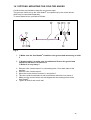
1
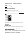
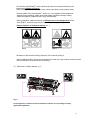
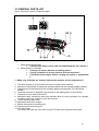
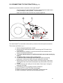
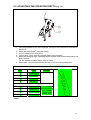
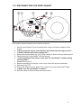
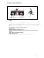
User manual and parts book Verti-Quake® Redexim REDEXIM BV INTERNATIONAL TRADING KWEKERIJWEG 8 3709 JA ZEIST HOLLAND TEL (31) 30 6933227 FAX (31) 30 6933228 Model: 2510/2516/2521 [email protected] WWW.REDEXIM.COM Serial number: ATTENTION: TO ENSURE SAFE USE OF THIS MACHINE AND TO BE ABLE TO ACHIEVE THE BEST RESULTS, IT IS OF THE UTMOST IMPORTANCE TO READ THIS USER MANUAL THOROUGHLY BEFORE USING THE VERTIQUAKE®. 1113 English 915.120.202 FORWARD Congratulations on your purchase of the Verti-Quake®. To ensure the long and safe use of this Verti-Quake®, it is of the utmost importance for all those who will be using it to read and understand this user manual. Without full knowledge of its contents, it is not possible to safely work with this machine. The Verti-Quake® is not an independently operating machine. It is the user’s responsibility to use the right tractor. The user must also make sure the tractor/Verti-Quake® combination is provided with safety aspects such as noise reduction, user instructions, and risk analysis. The Verti-Quake® is solely intended for use on lawns and other areas where grass could grow. On the next page, you will first find the general safety instructions. Every user must know these and be able to apply them. After this, a registration card is included. This card should be returned in order to be able to follow up on any claims at a later stage. This user manual offers many instructions, which are numbered in sequence. This sequence should be followed. An asterisk * indicates a safety instruction. An ‘at’-sign @ indicates a tip or note. WARRANTY CONDITIONS THIS VERTI-QUAKE® IS DELIVERED WITH A WARRANTY AGAINST DEFECTS IN MATERIALS. THIS WARRANTY IS VALID FOR A PERIOD OF 12 MONTHS FROM DATE OF PURCHASE. VERTI-QUAKE® WARRANTIES ARE SUBJECT TO THE “GENERAL CONDITIONS FOR SUPPLY OF PLANT AND MACHINERY FOR EXPORT, NUMBER 188”, WHICH ARE PUBLISHED UNDER THE AUSPICES OF THE UNITED NATIONS ECONOMIC COMMISSION FOR EUROPE. REGISTRATION CARD For your own information, please fill in the table below: Serial number machine Dealer name Date of purchase Remarks 2 SAFETY INSTRUCTIONS Fig. 1 ! The design of the Verti-Quake® allows for safe use. But this is only possible if the user completely follows all safety instructions as described in this manual. Read and understand (Fig. 1) the manual before beginning to use the Verti-Quake®. If the machine is not used as described in the manual, injury and/or damage to the Verti-Quake® may result. (1) The Verti-Quake® is solely intended for the treatment of lawns or other areas where grass should grow. Any other use is considered incorrect use. The manufacturer accepts no liability whatsoever with regard to damage resulting from such incorrect use. Any resulting risks are completely for the account of the user. Correct use also includes following the manufacturer’s instructions for usage, maintenance and repair. Before using the Verti-Quake®, inspect the area to be treated. Remove any loose obstacles and avoid irregularities. (2) The Verti-Quake® was constructed according to the latest technological knowledge and is safe to use. If the machine is used, maintained or repaired by inexpert persons, this may result in injury to both the user and third parties. This should be avoided! Always use the Verti-Quake® in combination with the proper tractor as described in the technical data. (3) All persons whom the owner assigns to operate, maintain or repair the VertiQuake® must read and have completely understood the operating manual and in particular the Section Safety Instructions. The user is responsible for a safe tractor/ Verti Quake® combination. This entire unit must be tested in terms of noise, risk, and user convenience. In addition, user’s instructions must be prepared. (4) The user is obliged, before using the Verti-Quake®, to check it for visible damage and defects. Any changes in the Verti-Quake® (including its functioning) that may affect its safety must be corrected immediately. For reasons of safety, any modifications or additions to the Verti-Quake® (with the exception of those approved by the manufacturer) are not permitted in principle. If any modifications have been made to the Verti-Quake®, the present CE certificate becomes null and void and the person who made the modifications should himself make sure a new CE certificate is granted. 3 Before each use, inspect the Verti-Quake® for loose bolts/nuts/parts. If present, inspect the hydraulic hoses regularly and replace these if they are damaged or show signs of wear. The replacement hoses must meet the manufacturer’s technical specifications. Always relieve the pressure from the hydraulic installation, if present, before carrying out any work on it. NEVER use de Verti-Quake® if its protective covers and safety decals are missing. NEVER crawl underneath the Verti-Quake®. If you need to access the bottom, tilt the Verti-Quake®. NEVER step off the tractor while the engine is still running. When carrying out maintenance, adjustments or repairs, make sure the VertiQuake® is blocked from sagging/moving/sliding. Before carrying out any maintenance, adjustments or repairs, always switch off the tractor engine first, remove the tractor key from the ignition, and disconnect the PTO (Fig. 2). Fig. 2 When carrying out any maintenance or repairs, make sure to use original VertiQuake® parts only. This will ensure continued safety of the machine and its user. Only authorised technical personnel may carry out adjustments and repair work to the Verti-Quake®. Keep a log of all repairs. (5) In addition to the instructions in this user manual, the generally applicable health and safety guidelines must be followed. When used on public roads, the relevant traffic regulations apply. Transport of persons is not permitted! Do not use the Verti-Quake® when it is dark, during heavy rain/ storms, or on slopes with a gradient greater than 20 degrees. (6) Before embarking on any job, all persons operating the VertiQuake® must be familiar with its functions and operating elements. 4 Connect the Verti-Quake® to the vehicle that will pull it exactly according to the instructions (Danger of injury!) Before driving off, make sure you have a clear view both nearby and far away. On both sides of the Verti-Quake®, decals (Fig. 5) are applied to the sideboard showing these warnings. Make sure these safety decals are always clearly visible and legible. Replace them if they are damaged. During operation, make sure there are NO persons in the danger area of the Verti-Quake®, because they may be injured by rotating parts. (Fig. 3) Keep a distance of at least 4 metres! (Fig. 4) Fig. 3 Fig. 4 Be aware of the maximum lifting capacity of the vehicle pulling it. Wear suitable clothing. Wear sturdy shoes with a steel tip, long trousers, keep long hair tied up and wear no loose articles of clothing. (7) Placement of safety decals. (Fig 5.) Fig. 5 Used oil/grease is harmful to the environment; dispose of it according to locally applicable regulations. 5 CONTENTS Section Description Page Preface 2 Warranty conditions 2 Registration card 2 Safety instructions 3 1.0 Technical data 7 2.0 First installation, removing the machine from the pallet 8 2.1 Prepare machine for operation 9 3.0 General parts list 10 4.0 The PTO 11 4.1 Length of the PTO 11 4.2 Operation of the PTO 12 4.3 PTO information and maintenance 12 5.0 Connecting to the tractor 13 6.0 Adjusting the operating depth 14 7.0 Driving speed 15 8.0 Start/stop procedure 9.0 10.0 15 Operation of the Verti-Quake ® 16 Transportation of the Verti-Quake 11.0 Disconnecting the Verti-Quake 12.0 Troubleshooting 13.0 Maintenance ® ® 16 17 18 19 ® 13.1 Cleaning the Verti-Quake 19 13.2 Replacing/mounting the knives 20 14.0 Options: Undeep Aerating Kit 21 14.1 Options: Mounting the coulter knives 22 15.0 EU certificate 23 6 1.0 TECHNICAL DATA Model 2510 2515 2521 Operating width 1.1 m (43”) 1.6 m (63”) 2.1 m (82.7”) Operating depth 250 mm (9.8”) 250 mm (9.8”) 250 mm (9.8”) Tractor speed measured at 540 rev/min on PTO. 0.5 - 1.5 Km/h 0.5 - 1.5 Km/h 0.5 - 1.5 Km/h 0.3 - 0.9 mph 0.3 - 0.9 mph 0.3 - 0.9 mph PTO speed (rpm): (max.) Weight 540 540 540 470 Kg 575Kg 690 Kg 1189 lbs 1355 lbs 1521 lbs 12 18 24 Number of knife discs 4 6 8 Distance between knife discs Knife thickness 260 mm (10.2”) 260 mm (10.2”) 260 mm (10.2”) 12 mm (0.47”) 12 mm (0.47”) 12 mm (0.47”) 30-45 hp 35-55 hp 650 Kg /1432 lbs 750 Kg /1653 lbs 850 Kg /1873 lbs 1650 m2/h 2400 m2/h 3150 m2/h 17760 ft2/h 25833 ft2/h 33906 ft2/h 1,28x0,83x1,50m 1,78x0,83x1,50m 50”x32.7x59” 70.1”x32.7x59” 2,30x0,83x1,50 m Number of knives Recommended tractor 20-30 hp Minimum lifting capacity Hydraulic connection Maximum treatment capacity Shipping measurements 90.6”x32.7”x59” Three-point connection Gearbox oil Cat. 1 & 2 Cat. 1 & 2 Cat. 1 & 2 SAE 90 SAE 90 SAE 90 Lubricant EP2 EP2 EP2 Standard parts -Knives 12 mm (0,47”) -Knives 12 mm (0,47”) -Knives 12 mm (0,47”) -Back roller -Back roller -Back roller -Integrated adjustable -Integrated adjustable -Integrated legs legs adjustable legs -PTO with Cam-PTO with Camclutch clutch -PTO with Camclutch Options -Coulter knives -Coulter knives -Coulter knives -Undeep Aerating Kit -Undeep Aerating Kit -Undeep Aerating Kit 7 Position 1 Position 2 Position 3 1 2 Fig. 6 2.0 FIRST INSTALLATION, REMOVING THE MACHINE FROM THE PALLET The machine is located vertically on the pallet. To remove the pallet and lay the machine horizontally, carry out the following steps (fig. 6): *!! DO NOT CRAWL UNDER THE MACHINE !! 1. Mount a cable to the lifting points at both sides of the machine. (fig. 6 Position 1) * Make sure that the cable/crane/lift can lift at least 2000 kg (4400 lbs) (for the models 2516 and 2521) 2. Raise the machine, including the pallet, 50 mm from the ground. 3. Make sure that the machine is on the point of the pallet. (fig. 6 Position 2) 4. Gently lower the machine, in a controlled way, until it fully rests upon the ground. (fig. 6 Position 3) *!! BE CAREFUL – KEEP YOUR DISTANCE – THE MACHINE MAY SHIFT !! 5. Remove the Top three-point pins 1 6. Remove the bottom three-point pins 3 and remove the pallet. 8 2 1 3 1 4 5 6 Fig. 7 2.1 PREPARING THE MACHINE FOR OPERATION 1. Loosen the bolts 1. Remove the access hatches 2. (fig. 7) 2. Remove the loose parts, which were supplied with the machine, from it. *!! Be careful – the knives are sharp !! 3. Couple the machine to a tractor. See Section 5.0. * Use the correct tractor. See the specifications. 4. 5. 6. 7. 8. Raise the machine off the ground. *!! Ensure that the tractor is well blocked and cannot start moving by itself!! *!! Switch off the tractor before getting off !! Lower the adjustable legs 4 of the machine and secure them using the handles 3. Carefully lower the machine onto the adjustable legs 4. *!! BEFORE GETTING OFF THE TRACTOR, MAKE SURE THAT THE TRACTOR AND THE VERTI-QUAKE® ARE FIRMLY PLACED ON THE GROUND AND CANNOT SAG OR SLIDE !! Fig.8 9. Loosen bolts 5 & 6 10. Mount the knives with the sharp edge pointing towards the back roller of the machine. *!! Be careful – the knives are sharp !! Tighten bolts 5 & 6 well. 11. Mount the bleeder, which was included in the delivery, onto the top of the gearbox. 12. Mount the access hatches 2 and secure these by tightening bolts 1. (fig. 7) 13. Set the tractor’s stabiliser to 50 mm lateral movement. 14. Determine the length of the PTO according to Section 4. 9 3.0 GENERAL PARTS LIST Figure 9 shows a number of important parts: Fig. 9 1. Safety decal 900.280.402: *!! Before use, make sure to read and understand the user manual !! 2. Safety decal 911.280.402: *!! Danger of injuries because of rotating parts !! *!! Keep a distance of at least 4 metres from the machine !! *!! Stop the tractor engine before carrying out repairs or adjustments !! * !! Make sure all decals are clearly visible on the machine and are understood !! 3. The serial number is on the bottom left on the outside of the machine. 4. Adjustment mechanism to adjust the operating depth and the operating-depth indicator. 5. Dragging legs for adjustment of the operating depth and integrated Turf Hold Down system. 6. Inspection hatches for inspection and access to the rotating parts of the machine. 7. Container for user manual and tools. 8. Adjustment legs, intended to secure the machine when it is not in operation, for example to enable work to be carried out onto the machine. 9. Terrain-following back roller. 10. Adjustable back-roller scraper. 11. Bottom three-point connecting pins. 12. Top three-point connecting pin. 13. PTO input shaft. The safety side (with the cam-clutch) of the PTO has to be mounted to this shaft. 10 4.0 THE PTO The PTO is a very important part. It takes care of the drive from the tractor and ensures safe use of the machine – if installed, used, and maintained correctly. The PTO has its own CEcertificate. Make sure to read the PTO manual. It is located on the PTO itself. Fig. 10 4.1 LENGTH OF THE PTO (fig. 10) The length of the PTO is very important. If it is too long, it may damage the drive of the tractor and/or the Verti-Quake®. If the overlapping length of the sleeves is, at any time, shorter than 150 mm, the PTO may be damaged. *!! The length will vary when the machine is raised or if another tractor is used !! To make sure the length of the PTO is correct, after purchase or when using another tractor, carry out the following steps: 1. Connect the Verti-Quake® to the tractor, as described in Section 2.1. 2. * !! Switch off the tractor and make sure the tractor is properly blocked and cannot start moving by itself !! 3. Lower the Verti-Quake® to the ground until the knives are almost touching the ground and the dragging legs are parallel with the ground. 4. Measure the distance between the PTO connection of the tractor and that of the VertiQuake®, from one furrow to the next. 5. Measure the distance B of the PTO at its shortest position, from locking pin to locking bolt. 6. Divide the PTO up into two parts and remove the protective cover from both ends. 7. Both the sleeve ends and the cover ends have to be shortened: (B-A) + 75 mm (3”). 8. Deburr, grease, then assemble all parts. 9. Mount the PTO with the cam-clutch side facing the Verti-Quake®. 10. Mount the other end of the PTO to the tractor. 11. Check the overlap of the sleeves. * !! Never use the machine if the protective cover of the PTO is damaged. Replace it first. !! 11 4.2 OPERATION OF THE PTO To ensure correct operation of the PTO, check the following items: 1. During operation of the Verti-Quake®, the angle between the points of rotation may not exceed 30 degrees. 2. The rotating points should be aligned. 3. The overlap of the sleeves must be at least 150 mm. 4. Never use the machine if the protective cover of the PTO is damaged. 4.3 PTO INFORMATION AND MAINTENANCE The PTO intended for use with your Verti-Quake® machine is provided with a cam-clutch safety device, which protects the Verti-Quake® against overloading. *!! If the cam-clutch is activated, the PTO has to be put off, the machine to be lifted out of the ground and the start procedure has to be repeated!! Summarised PTO maintenance schedule. Periodic maintenance: Grease the lubricating points after every 100 hours of operation or when the PTO was not used for a while. Check the PTO for signs of damage to the protective covers and replace these if necessary. Make sure all safety decals are present on the PTO and that they are undamaged. Annual maintenance: Remove the PTO from the machine. Carefully check all parts of the PTO. Replace all parts that are damaged. Put down all parts and check them carefully. If any parts show signs of damage or wear, replace these. Clean all parts that interlock or engage. Reassemble the parts. Grease both sleeves and reassemble the two PTO halves. Reassemble the PTO and mount it to the machine. For further information concerning maintenance and assembly of the PTO, please refer to the manual included with the PTO. @ If the PTO was shortened incorrectly, or if another tractor was used, the gearbox may be overloaded. This may result in damages. 12 5.0 CONNECTING TO THE TRACTOR (Fig. 11) Inspection procedure before connection of the Verti-Quake®: Visually inspect the Verti-Quake® for signs of damage and repair these if they endanger a safe operation of the machine. Make sure that all nuts and bolts are properly tightened. Fig. 11 The Verti-Quake® is connected to the tractor by means of the three-point connection. This is done as follows: (fig.11) 1. Remove the three-point pins 1 and 2 2. Mount the PTO with the cam-clutch side facing the PTO shaft of the Verti-Quake®. 3. Drive the tractor carefully in reverse so that the low connection arms can be connected to the frame. 4. *!! Ensure that the tractor is well blocked and cannot start moving by itself !! 5. *!! Switch off the tractor before getting off !! 6. Connect the lower connecting arms to the three-point connecting plates pins 1 and secure these using the safety pins included. 7. Mount the top rod of your tractor and pull it out by turning it until it has reached the same level as the three-point stop connection of the VertiQuake®. 8. Connect the top rod 3 with pin 2 to the frame. Secure pin 2 using the safety pin included. 9. Push the top rod in by turning in order to tension it. 10. Mount the PTO to the PTO shaft of the tractor. 11. Start the tractor and raise the Verti-Quake® from the ground. 12. Slide out handles 4 and slide up the adjustable legs 5. 13 6.0 ADJUSTING THE OPERATING DEPTH (Fig. 12) Fig. 12 1. If the Verti-Quake® is not yet connected, connect it to the tractor as described in Section 5. 2. Raise the Verti-Quake® using the tractor. 3. Pull out safety pins 2 from pins 1 . 4. Pull out pins 1 from the frame on both sides of the machine. 5. Adjust the dragging legs / operating-depth indicator until the desired position has been reached. For the desired operating depth, refer to Table 1. 6. Mount pins 1 into the desired hole and secure the pins using safety pins Adjustment of the operating depth (new knives) Hole Depth 1 250 mm (9.8”) 2 230 mm (9”) 3 205 mm (8”) 4 180 mm (7”) 31 165 mm (6.5”) 1 145 mm (5.7”) 51 125 mm (4.9”) 61 105 mm (4.1”) 4 Remarks 1 Only possible with the special kit for undeep aeration (See section 14.0) 6 5 4 3 2 1 Table 1 14 7.0 DRIVING SPEED The effectiveness of the aeration depends upon the condition of the soil, the driving speed, and the speed (rpm) of the PTO. To aerate using the Verti-Quake®, a driving speed of between 0.5 and 1.5 km/h (0.3 – 0.9 mph) is recommended, in combination with a PTO speed of max. 540 rpm. The driving speed and the rpm of the PTO should be adjusted according to the soil condition and the amount of aeration needed. 8.0 START/STOP PROCEDURE The start procedure is VERY important. If this procedure is not followed exactly as described below, serious damage may occur to the Verti-Quake®. The start procedure is as follows: 1. Visually inspect the Verti-Quake® and make sure all parts are functioning properly. *!! If they are not, these problems must be resolved before the Verti-Quake® is to be used !! 2. Check the oil level in the gearbox. The oil level should be in the centre of the gauge glass. 3. Connect the Verti-Quake® to the tractor. 4. Drive to the place where the soil is to be treated. 5. Lower the machine until the knives are almost touching the ground. 6. Switch on the four-wheel drive. Switch on the tractor in the right gear. 7. Switch on the PTO at a low speed (rpm). 8. Slowly raise the PTO speed to approx. 300 rpm. 9. Start the tractor moving and smoothly lower the Verti-Quake® into the ground. 10. Raise the PTO speed to a maximum speed of 540 rpm. 11. Raise the driving speed to a maximum of 1.5 km/h (0.9 mph) Fig 12 @ Adjust the top rod in such a way that the rear part of the dragging legs are parallel to the ground. This will reduce the pressure of the machine on the ground and will prevent damage to the soil. (fig. 12) @ Always work in straight lines. Curves may damage the soil to be treated. 15 Stopping is done as follows: 1. Stop the forward movement of the tractor. 2. Slowly reduce the PTO speed to approx. 300 rpm. 3. Stop the PTO as soon as the knives are out of the soil. 4. Gradually raise the Verti-Quake® from the soil. 5. Drive to the next place and start again as described at the beginning of this Section. *!! NEVER operate the tractor gears when the Verti-Quake® is operated. The Verti-Quake® may push the tractor forward at high speed!! @ It is absolutely imperative that the above procedures are followed. If the machine is placed into the soil while the PTO is not running, this may cause serious damage to the machine. @ Always lower the Verti-Quake® into the soil VERY CAREFULLY. @ The machine is protected by a cam-clutch safety device built in the PTO (See section PTO) 9.0 OPERATION OF THE VERTI-QUAKE® Before the Verti-Quake® is used in any place, the following should be checked first: 1. Are there any loose objects lying about in the field? Remove these first. 2. Are there any slopes? The maximum slope for the Verti-Quake® is 20 degrees. Make sure to always move downhill. 3. Does the ground contain cables or pipes? If so, determine their depth and set the operating depth of the machine to 60% of this depth. 4. Does the ground contain hard objects? Adjust the operating depth accordingly. 5. Is there any danger of flying objects, such as golf balls, which may distract the attention of the driver? If so, do NOT use the Verti-Quake®. 6. Is there any danger of sagging or sliding? If so, postpone working with the Verti-Quake®. 7. If the soil is frozen or very wet, the treatment should be postponed until the circumstances are more favourable. 10.0 TRANSPORT OF THE VERTI-QUAKE® The user is responsible for the transport of the Verti-Quake® behind the tractor when travelling public roads. Check the national traffic regulations. On open fields, a maximum speed of 12 km/h (7.5 mph) should be observed, because of the weight of the Verti-Quake®. A higher speed may endanger the driver and/or other people and may even damage the machine. * When the machine is in raised position, at least 20% of the weight of the tractor should be supported by the front axle. 16 11.0 DISCONNECTING THE VERTI-QUAKE® Fig. 13 The machine is disconnected from the tractor as follows: 1. Drive the Verti-Quake® up to its storage place, which must have a stable and flat ground. 2. *!! Ensure that the tractor is well blocked and cannot start moving by itself !! 3. *!! Switch off the tractor before getting off !! 4. Slide down the adjustable legs 1 by pulling handles 2. Secure the legs with handle 2. 5. Carefully lower the Verti-Quake® onto the ground. 6. * !! Before getting off the tractor, make sure the Verti-Quake® is stably resting on the ground !! 7. Release the top rod 3. 8. Remove the safety pin from pin 4. Pull out pin 4 from the top-rod connection. 9. Disconnect the PTO. 10. Pull out the safety pins from pins 5. Pull out pins 5 from the Verti-Quake® frame. 11. *!! Make sure the Verti-Quake® is stable !! 12. Start the tractor and drive it away from the machine. 17 12.0 TROUBLESHOOTING Problem Possible cause Too much damage to the Knives are damaged. soil to be treated. Solution Try aligning the knives by straightening them using a hammer and anvil. Knives are crooked. Align the knives. Mount new ones. Machine is not in line with the tractor. Adjust the machine to align the knives with the tractor. Not driven in a straight line. Try driving in a straight line. Soil is too wet. Postpone the job until the soil has dried. Cam-clutch is engaged. Repeat starting procedure Drive chain has broken. Repair or replace the chain. Gearbox damaged. Repair or replace the gearbox. Gearbox is leaking. Seal is leaking. Replace seal. Cam-clutch is engaged too much. Cam-clutch is worn out Replace cam-clutch Too many stones or rocks. Adjust the operating depth. Ground is too hard. Adjust the operating depth. Driving speed is too high. Adjust the driving speed. PTO speed is too low. Increase the PTO speed (rpm). Tractor is too light. Weigh down the tractor or choose another type of tractor. Driving speed is too high. Adjust the driving speed. Too fast driving. Drive more slowly. Soil is too wet. Postpone the job until the soil has dried. PTO speed (rpm) is too low. Raise the PTO speed (rpm). Knives are crooked. Align the knives. Mount new ones. Soil is too wet. Postpone the job until the soil has dried. The aerator shaft is not turning. Machine is pushing the tractor forward. Soil is insufficiently aerated. Knives are bringing up too much soil. 18 13.0 MAINTENANCE To protect machine and user, all adjustment and repair work carried out to the Verti-Quake® may only be performed by authorised technical staff. When carrying out any maintenance or repairs, make sure to use original Verti-Quake® parts only. This will ensure continued safety of the machine and its user. Time schedule Before each use After every 8 operating hours. Check point / lubricating point Check for loose bolts/nuts. Check the oil level in the gearbox. The oil level should be in or above the centre of the gauge glass. Connect the machine to the tractor and leave the machine running without load for five minutes. Check for loose bolts/nuts. Method Tighten loose bolts/nuts. Use SAE 90 Look and listen for any strange noises and movements. Tighten loose bolts/nuts. Presence and legibility of safety Replace these if damaged. decals. (See Fig. 5) Any loose parts around the PTO. Secure these parts so that they cannot come too close to the PTO. Grease the PTO lubricating Use EP2 lubricating grease. points. After every 50 operating hours. Check the gearbox for oil leakage. Replace gearbox seals. After every 100 operating hours. Check the knives. Replace or repair them. 13.1 CLEANING THE VERTI-QUAKE® Please follow the cleaning instructions below to maintain an optimum condition for the Verti-Quake®. Never point a high-pressure cleaner at the bearing seals. After cleaning, grease all lubricating points. Never use aggressive soap or cleaning agents. Make sure the Verti-Quake® is switched off before cleaning it. Make sure the machine is stable and cannot sag or slide. Make sure the safety decals remain clearly visible. 19 13.3 REPLACING THE KNIVES 2 4 3 1 1 Fig.15 If new or other knives are to be mounted, proceed as follows. (See Fig. 15): 1. *!! Make sure the Verti-Quake® is stable on the ground and cannot sag or slide !! 2. Loosen the bolts 1. Remove the access hatches 2. 3. Remove bolts 3. 4. Untighten the bolts 4 to get some clearance. 5. Remove the knives to be replaced. 6. Mount the new knives with the sharp edge pointing towards the back roller of the machine. *!! Be careful – the knives are sharp !! Tighten bolts 3 & 4 well. 7. Mount the access hatches 2 and secure these by tightening bolts 1. 20 14.0 OPTIONS: UNDEEP AERATION KIT When less deeper aeration is requested that can be achieved with the standard settings the solution is installing an undeep aeration kit. To mount this kit, proceed as follows: Fig.16 1. *!! Make sure the Verti-Quake® is stable on the ground and cannot sag or slide !! *!! Support the front side of the dragging legs 6 !! 2. Remove bolts 4 and nuts 5. 3. Mount the strips 1 with bolts 2 and nuts 3; Tighten the assembly well. 4. Mount dragging legs 6 with bolts 4 and nuts 5 onto the strips 1. Tighten the assembly well. For depth settings look at section 6.0 21 14.1 OPTIONS: MOUNTING THE COULTER KNIVES Coulter knives are intended to keep the cut grooves open. The grooves, freshly cut by the Verti-Quake®, are opened up by the coulter knives, which may be connected separately. To mount these knives, proceed as follows: Fig.17 1. *!! Make sure the Verti-Quake® is stable on the ground and cannot sag or slide !! 2. *!! Support roller 2 to make sure it is stable and firm on the ground and cannot roll off when it is removed !! *!! Roller 2 is very heavy !! 3. Remove roller 2 and scraper 3 by unscrewing bolts 1 from both sides of the machine. 4. Remove roller 2 and scraper 3. 5. Mount the coulter knives to sleeve 9, using bolts 6. 6. Take the coulter kniveholders 4 and mount these with bolts 6 on sleeve 9 7. Make sure the coulter knives are well aligned with the rotating knives of the Verti-Quake®. 8. Tighten all bolts 6 and nuts 8 well. 22 15.0 EU-DECLARATION We – Redexim BV, Utrechtseweg 127, 3702 AC Zeist, Holland – declare entirely under our own responsibility that the product VERTI-QUAKE MODEL 2510/2516/2521, WITH MACHINE NUMBER AS INDICATED ON THE MACHINE AND IN THIS MANUAL to which this declaration refers, complies with stipulation of the 2006/42/EC machine directive. Zeist, 28.03.11 A.C. Bos Manager Operations & Logistics Redexim Holland 23