1
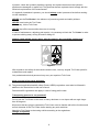
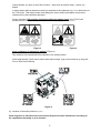
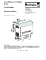
User Manual and Parts Book Turf-Cutter Serial number: Kwekerijweg 8 3709JA Zeist The Netherlands Tel.: (31)306933227 Fax: (31)306933228 Email: [email protected] www.redexim.com Translation of the original User Manual ATTENTION: IT IS OF THE UTMOST IMPORTANCE TO READ THIS USER MANUAL CAREFULLY PRIOR TO USING THE TURF-CUTTER IN ORDER TO USE THE MACHINE SAFELY AND TO OBTAIN THE BEST RESULTS. 1334 English 956.120.000 FOREWORD Congratulations on your Turf-Cutter purchase! For safe and long-lasting operation of this TurfCutter, it is necessary to read and to understand this user manual. It is impossible to work safely with this machine without complete knowledge of the content of the user manual. The Turf-Cutter is not a machine that works independently. It is the user’s responsibility to use the correct tractor. The user must also check the tractor/Turf-Cutter combination on safety aspects such as noise level, user instructions and risk analysis. The Turf-Cutter is solely intended for grass fields or areas where grass can grow. The following pages deal initially with the general safety instructions. Every user should know these safety instructions and apply them. At the end of this page, a registration card is inserted. This registration card should be returned to us in order to deal with potential future claims. This user manual lists many instructions that are numbered in sequence. You should follow this sequence. A is an indication of a safety instruction. A means a tip and/or note. All information and technical specifications provided at the moment that this document is published are the most recent ones. Design specifications may be changed without prior notice. This document is a translation of the original operating instructions. Upon request, the original operating instructions are available in Dutch. WARRANTY CONDITIONS WITH DELIVERY THIS TURF-CUTTER IS GUARANTEED AGAINST MATERIAL DEFECTS. THIS WARRANTY IS VALID FOR A PERIOD OF 12 MONTHS FROM THE PURCHASE DATE. TURF-CUTTER WARRANTIES ARE SUBJECT TO THE ‘GENERAL CONDITIONS FOR SUPPLY OF PLANT AND MACHINERY FOR EXPORT, NUMBER 188’ THAT ARE PUBLISHED UNDER THE AUSPICES OF THE UNITED NATIONS ECONOMIC COMMISSION FOR EUROPE. REGISTRATION CARD For your own information, fill in the table below: Serial number of the machine Dealer name Date of purchase Remarks 2 ! SAFETY INSTRUCTIONS ! Figure 1 The Turf-Cutter is designed for safe use. This can only be achieved if you completely follow the safety instructions described in this manual. Read and understand (Figure 1) the manual before you start using the Turf-Cutter. If the machine is not used as described in this manual, this can result in injuries and/or damage to the Turf-Cutter. (1) The Turf-Cutter is solely intended for work on grass fields or areas where grass can grow. The manufacturer will not accept any liability for unprofessional use and its resulting damage. All risks occurring with this are entirely at the expense of the user. Following the use, maintenance and repair instructions prescribed by the manufacturer is also considered professional use of this machine. Inspect the area to be treated before using the Turf-Cutter. Remove loose obstacles and avoid irregularities. (2) The Turf-Cutter is manufactured according to the latest technical understanding and is safe to use. When unskilled people use, maintain or repair the machine, this could result in injuries to the user and to third parties. This must be avoided! Always use the Turf-Cutter in combination with the correct tractor as described in the technical data. (3) All persons assigned to operate, maintain and repair the Turf-Cutter by the owner must completely read and understand the operation manual and in particular the chapter of Safety Instructions. The user is responsible for a safe Tractor/Turf-Cutter combination. This entire combination must be tested for noise, safety, risk and user friendliness. User instructions should also be drafted. (4) The user is obliged to check the Turf-Cutter for visible damage and defects before using the Turf-Cutter. Modifications to the Turf-Cutter (including its operations) that have a negative impact on safety must be rectified immediately. For safety reasons it is in principle not permitted to make changes or adjustments to the TurfCutter (except those approved by the manufacturer). If modifications to the Turf-Cutter have been made, then the current CE marking is cancelled. The person that has made these modifications has to apply for a new CE marking himself. Check the Turf-Cutter for loose bolts, nuts and components before every operation. 3 If present, check the hydraulic pipelines regularly and replace these when the hydraulic pipelines are damaged or appear old. The pipelines that are replaced should comply with the technical requirements of the manufacturer. If a hydraulic installation is present, you should always make it pressure-free before working on this installation. NEVER use the Turf-Cutter in the absence of protective guards and safety stickers. NEVER crawl under the Turf-Cutter. If necessary, tilt the Turf-Cutter. NEVER step off the tractor while the motor is running. In case of maintenance, adjusting and repairs, it is necessary to block the Turf-Cutter in order to prevent sinking away, driving off and/or sliding off. Always switch off the tractor motor, take the tractor’s key out off the ignition and disconnect the PTO in case of maintenance, adjusting and repairs. (Figure 2). Figure 2 With regards to the safety of the machine and the user, use only original Turf-Cutter parts for maintenance and repairs. Only authorised technical personnel may carry out repairs to Turf-Cutter. Keep a record of the repair activities. (5) The general applicable health & safety (Dutch: ARBO) regulations must also be followed in addition to the instructions in this user manual. Relevant traffic regulations also apply in case of using public roads. Transporting persons is not permitted! Do not use the Turf-Cutter in the dark, in heavy rain/storm or on slopes with an angle larger than 20 degrees. All persons that are going to operate the Turf-Cutter must be familiar with all the functions and control elements of the Turf-Cutter before starting any work activities. Attach the Turf-Cutter to the towing vehicle according to the regulations. (Danger of injuries!) 4 Check whether you have a clear field of vision – both close by and far away – before you depart. A safety sticker with an identical meaning is attached to the sideboard (Figure 5) on both sides of the Turf-Cutter. This safety sticker must always be clearly visible and legible and must be replaced if they have become damaged. During operation, NO persons are allowed within the danger zone of the Turf-Cutter, because there is danger of physical injuries caused by flying material (Figure 3). Figure 3 Figure 4 Keep a distance of minimum 4 metres! (Figure 4) Pay attention to the permitted lifting capacity of the towing vehicle. Dress appropriately. Wear sturdy shoes with steel toecaps, long trousers and tie up long hair. Do not wear loose clothing. Figure 5 (6) Location of the safety stickers (Figure 5) Used oil/grease is harmful to the environment. Dispose of these substances according to the regulations that apply in your location. 5 EU DECLARATION We – Redexim BV, Utrechtseweg 127, 3702 AC Zeist, Holland – declare entirely under our own responsibility that the product: TURF-CUTTER WITH A MACHINE NUMBER AS INDICATED ON THE MACHINE AND INDICATED IN THIS MANUAL to which this declaration refers, complies with stipulation of the 2006/42/EC machine directive. Zeist, 21.08.13 A.C. Bos Manager Operations & Logistics Redexim Holland 6 TABLE OF CONTENTS 1.0 2.0 3.0 4.0 5.0 5.1 5.2 6.0 7.0 8.0 9.0 10.0 11.0 12.0 13.0 14.0 WARRANTY CONDITIONS ............................................................................................... 2 REGISTRATION CARD ..................................................................................................... 2 ! SAFETY INSTRUCTIONS ! ............................................................................................. 3 EU DECLARATION ........................................................................................................... 6 TECHNICAL DATA ............................................................................................................. 8 GENERAL DESCRIPTION ................................................................................................. 8 FIRST INSTALLATION OF THE TURF-CUTTER ............................................................... 9 ATTACHING / DETACHING THE TURF-CUTTER........................................................... 10 THE PTO........................................................................................................................... 11 LENGTH OF THE PTO ..................................................................................................... 11 USING THE PTO .............................................................................................................. 11 ADJUSTING THE WORKING DEPTH AND KNIFE ANGLE ............................................ 12 TRANSPORTING THE TURF-CUTTER ........................................................................... 13 THE WORKING SPEED ................................................................................................... 13 USING THE TURF-CUTTER ............................................................................................ 13 START/STOP PROCEDURE OF THE TURF-CUTTER ................................................... 13 TROUBLE SHOOTING (PROBLEM ANALYSIS) ............................................................. 14 MAINTENANCE ................................................................................................................ 15 CHANGING / REPLACING THE KNIVE ........................................................................... 17 STRETCHING THE CHAIN/REPLACING THE SHEARING PIN SAFETY ....................... 18 7 1.0 TECHNICAL DATA Model Turf-Cutter Working width Working depth 457mm (18”) / 610mm (24”) Working speed Depending on the conditions Recommended tractor PTO revs 18 HP with minimum lifting capacity of 300 kg (661 lbs) Maximum 540 rpm Weight 258 kg (568.8 lbs) Capacity 1830 m2/h (10764 ft2/h) 0 mm - 60mm (0”-2.36”) (Theoretical at a speed of 3 km/h (1.9mph) and with a knife of 610 mm (24”)) Dimensions (L x W x H) 648 x 710 x 826 mm 25.5” x 28” x 32.5” Oil gearbox SAE 90 Grease EP 2 Standard components - Knife 610 mm (24”) - PTO Optional - Knife 457 mm (18”) 2.0 GENERAL DESCRIPTION The Turf-Cutter is a machine for cutting turf. 8 Figure 6 3.0 FIRST INSTALLATION OF THE TURF-CUTTER The machine is placed in the transport position on the pallet. To remove the pallet and to place the machine horizontally on the ground, you take the following steps (see Figure 6): !! NEVER CRAWL UNDER THE MACHINE !! 1. 2. 3. 4. Remove the separate machine components that are included in the delivery. Mount knife (1) and tighten the bolts with a torque of 40 N/m (29.5 lbf/ft). Slide the four legs (2) into their holders and turn them 90°. Attach a cable to the lifting eye. Make sure that the cable/crane/lift can hoist minimum twice the weight of the machine. (See Chapter 1.0 ‘Technical Data’ for the weight details.) 5. Lift the machine and turn it carefully until it stands on its legs (2). !! NEVER crawl under the machine !! 6. Remove the cable. 7. Remove the pallet (3) from the machine. 8. Attach the machine to a tractor. (See Chapter 4.0 for instructions about attaching to the tractor.) 9 4.0 ATTACHING / DETACHING THE TURF-CUTTER Checking procedure before starting to attach the Turf-Cutter: Check the Turf-Cutter for visually discernible damage and repair this if safe operation of the machine is no longer guaranteed. Check whether all the nuts and bolts are tight. Check whether all protection caps and all safety stickers are present on the machine and are not damaged. NEVER use the machine without these items. Figure 7 The Turf-Cutter can be attached to the tractor by means of the 3-point attachment. Use the proper tractor (please refer to the specifications). The procedure is as follows (Figure 7): 1. Drive the tractor carefully backwards so that the lower connecting arms can be attached to the frame. !! Make sure that the tractor is blocked well and cannot move on its own accord !! !! Switch off the tractor before descending !! 2. Connect the lower connecting arms to the 3-point pins (1) and secure these with the supplied locking pins. It is also possible to use the slotted hole in order to let the machine follow the curves of the terrain more effectively. 3. Connect the top rod (2) to the frame with the pin (3); secure the pin (3) with the supplied locking pin. 4. 5. 6. 7. !! Make sure that all the fastening pins are locked !! Turn the top rod (3) inwards so that it becomes pressurized. Connect the PTO between the Turf-Cutter and the tractor. Start the tractor and lift the Turf-Cutter off the subsoil. Remove the legs (4). Detaching is done in reverse order. 10 5.0 THE PTO The PTO is a very important component that takes care of the drive from the tractor. It also takes care of safe use of the machine, provided it is installed and maintained in the correct manner. The PTO has its own CE certification. Read the PTO manual. This manual is located on the PTO. Figure 8 5.1 LENGTH OF THE PTO The length of the PTO is very important. If it is too long, it can damage the drive of the tractor and/or the Turf-Cutter. If the overlapping length of the cylinders becomes less than 150 mm (6”) at any time, it can damage the PTO. The length changes when the machine is lifted or when a different tractor is used! In order to set the PTO to the correct length, when a new one has been purchased or when a different tractor is used, follow these steps (see Figure 8): 1. Measure the distance between the PTO’s connection to the tractor and to the machine, from groove to groove, when the machine is connected to the tractor and positioned on the ground at the right angle. 2. Measure the distance B of the PTO in its shortest position from the locking pin to the locking bolt. 3. Divide the PTO in two parts and remove the protection cap at both ends. 4. The ends of the cylinders and the ends of the protection caps must be made shorter: (B-A) + 75 mm (3”). 5. Smooth off all components, use some grease, and then assemble all components. 6. Attach the other end of the PTO to the tractor. 7. Check the overlap of the cylinders. Never use the machine if it has a damaged PTO protection cap. First replace any damaged parts! 5.2 USING THE PTO The following items must be checked for correct use of the PTO: 1. While working the angle of the pivot pins may not exceed 30 degrees. 2. The pivot pins must always be aligned. 11 3. The overlap of the cylinders must always be minimum 150 mm. 4. Never use the machine if it has a damaged PTO protection cap. 5. For lubrication, please refer to Chapter 12.0 ‘Maintenance’. Figure 9 6.0 ADJUSTING THE WORKING DEPTH AND KNIFE ANGLE The working depth of the machine can be set by adjusting the spindles (1) at the topside of the machine. The procedure is as follows (see Figure 9): 1. Before you can turn the spindles, the check nuts (2) at both sides of the machine must be loosened using the spanner supplied with the machine. 2. The working depth is set by turning the spindles inward or outward. NEVER adjust the working depth at one side more than 6 turns; first compensate at the other side to prevent damage. 3. The saw teeth (3) can be used as working-depth indicator to adjust the machine at an equal depth at both sides. 4. When the desired working depth is achieved, you have to tighten the check nuts (2) at both sides of the machine. If the knife is blunt or the soil is too hard, the knife might not stay at the required depth and it will cut the turf poorly. In that case, it will help to adjust the knife angle, resulting in a more aggressive cut. By experimenting, you can determine the right knife angle for the prevailing conditions. Adjust the knife angle as follows (see Figure 9): 1. Loosen the nuts (5) on both sides of the machine. 2. Place the supplied spanner on the bolt of the arm (4) and set the desired angle. 3. Tighten the nuts (5) on both sides of the machine and check whether they are at equal depth using the indication sticker (6). 12 7.0 TRANSPORTING THE TURF-CUTTER The user is responsible for transporting the Turf-Cutter in back of the tractor over public roads. Verify the national legislation regarding the regulations. A maximum speed of 20 km/h (12.4 mph) – on condition that circumstances permit this – should be observed when driving over fields with the machine in a lifted position. Higher speeds can endanger the driver/public and may even damage the machine. When the machine is raised off the ground, the front axle of the tractor has to support minimum 20% of its weight. 8.0 THE WORKING SPEED The working speed of the Turf-Cutter depends on the condition of the subsoil. During work activities, choose the right speed by ‘reading’ the subsoil that should be treated in combination with the desired working depth. 9.0 USING THE TURF-CUTTER Before using the Turf-Cutter in a location, you should check the following items: 1. 2. 3. 4. 5. 6. Are there loose objects in the field? First remove these objects. Are there slopes? The maximum slope is 20 degrees for this machine. Always go from top to bottom. Is there danger of flying objects (e.g., balls) that distract the attention of the driver? If so, the Turf-Cutter CANNOT be used. Is there danger of sinking/sliding away? If so, postpone the processing until conditions improve. If the soil is wet, postpone the activities until conditions improve. Do not make sharp bends and preferably, drive in straight lines; otherwise you might damage the subsoil. 10.0 START / STOP PROCEDURE OF THE TURF-CUTTER The start procedure is VERY important. If this procedure is not executed as described below, serious damage to the machine / subsoil could be the result. The start procedure is as follows: 1. Check the Turf-Cutter for loose components and look whether all components function properly. 2. 3. 4. 5. 6. 7. 8. !! If loose components are observed or components do not function properly, the problems must be solved before using the Turf-Cutter !! Connect the machine (see Chapter 4.0) and lift it. Remove the legs (see Figure 7). Drive to the spot where the processing should take place. Put the machine on the surface that has to be treated and adjust the working depth of the machine statically as described in Chapter 6.0. Lift the machine. Engage the tractor in the correct gear. Adjust the tractor engine to around 1200 rpm and engage the PTO. 13 9. While driving, lower the machine slowly into the subsoil in a fluent movement until it reaches its set working depth and increase the revs of the PTO to 540 rpm. 10. For the first few meters: Check whether the required working depth is achieved. If necessary, adjust the working depth as described in Chapter 6.0. Stopping occurs as follows: 1. Decrease the engine revs to approx. 1200 rpm. 2. Lift the machine out of the ground in a fluent movement. 3. Switch the PTO off as soon as the knives no longer touch the subsoil. 4. Lift the machine even more. 5. Go to the next location and start again as described above. !! It is preferred to drive in straight lines. Otherwise, damage can occur to the subsoil and/or the machine !! 11.0 TROUBLE SHOOTING (PROBLEM ANALYSIS) Problem Possible cause - Solution - Replace the shearing pin. - Breaking of the shearing pin safety Running off of the chain - Mount the chain and stretch it. Squeaking noises during the machine’s operation - Bearings are worn out. - Replace the faulty bearings. Machine does not reach its working depth. - Knife is blunt / worn out. - Sharpen or replace the knife. - Subsoil is too hard. - Adjust the knife angle. Spray water on the subsoil. Knife is blunt / worn out. - Sharpen or replace the knife. Adjust the machine to more depth. - Inset the bottom 3-point pins into the slotted hole. Postpone treatment until conditions improve. Drive in a straight line during treatment. Knife does not move. Sloppy image of the field after processing - Machine is not adjusted deep enough. Machine does not follow the curves in the terrain. Subsoil is too wet/dry. Did not drive in a straight line. 14 - 12.0 MAINTENANCE Time schedule Check/Grease point Method - Check for loose bolts / nuts. - - Presence and readability of the safety stickers (Figure 5) - After every use - Clean the machine. - Watch out for the bearings if a high-pressure sprayer is used. After the first 20 working hours (new or repaired) - Check the bearings and the driveline. Check for loose bolts / nuts. Check the chain tension. - If required, replace the parts. Tighten loose bolts / nuts. If needed, stretch the chain. - Check the roller bearings and the driveline. - - Grease the chain. - - Grease the spindles. - Use thin grease that does not attract dirt. - Check for loose bolts / nuts. - Tighten loose bolts / nuts. - Check for oil leakage. Check the oil level in the gearbox. - Replace or repair Use SAE90 for the gearbox. - Change the oil in the gearbox. - Use SAE90 for the gearbox. Before every use After every 100 working hours or annually After every 500 working hours - Tighten loose bolts / nuts with the correct tightening moment. Replace these if not present or damaged. Use EP2 lubrication. If required, replace these parts. Use universal chain grease. Used oil / grease is harmful to the environment. Dispose of these substances according to the regulations that apply in your location. 15 Figure 11 16 13.0 CHANGING / REPLACING THE KNIVE The standard delivery of the machine includes a 610 mm (24”) knife. If you require a smaller working depth, you have the option to equip the machine with a 457 mm (18”) knife. (Available under kit number 256.061.000) Change the knife as follows (see Figure 11): !! Make sure that the Turf-Cutter is blocked well and cannot move on its own accord !! !! Make sure that the PTO is detached from the Turf-Cutter !! !! Watch out: the knives may be sharp !! 1. 2. 3. 4. CHANGING THE 610 mm (24”) KNIFE Remove the bolts and nuts (1) and the bushes (2). Remove the knife (3) and replace this one with another knife. Mount the bushes (2) at the outside of the arm and place the knife. Mount the bolts and nuts (1) and tighten these with a torque of 40 N/m (29.5 lbf/ft). PLACING THE 457 mm (18”) KNIFE For placing the 457 mm (18”) knife, it might be necessary to make the roller smaller by removing two roller segments. 1. At both sides of the roller, remove bolt (9), spring ring (8), washer (7), a single roller segment (4), bush (6) and scraper (5). 2. Reuse the removed spring ring (8) and washer (7). Tighten the M12x45 bolts at both sides of the machine (included in the kit of the 457 mm knife) so that the roller is fixed. 3. Mount the bushes (2) at the inside of the arm and place the knife. 4. Mount the bolts and nuts (1) and tighten these with a torque of 40 N/m (29.5 lbf/ft). 17 13.1 STRETCHING THE CHAIN / REPLACING THE SHEARING PIN SAFETY Figure 10 The Turf-Cutter is standard equipped with adjustable idler that keeps the chain taut. Depending of the frequency of using the machine, wear & tear to the driveline occurs and the chain should be brought to tension. Adjust the idler as follows (see Figure 10): !! Make sure that the Turf-Cutter is blocked well and cannot move on its own accord !! !! Make sure that the PTO is detached from the Turf-Cutter !! 1. Remove the safety guard (1). 2. Slightly loosen nut (2) so that the tension is just off and stretch the chain by sliding the idler (3). 3. Tighten nut (2). 4. Check whether the chain is well aligned and grease it, if necessary. 5. Remount the safety guard (1) and tighten it. The shearing pin safety is activated when the machine is overloaded, resulting in the interruption of the driveline to the knife – the machine will have stopped operating. Do the following to replace the shearing pin: !! Make sure that the Turf-Cutter is blocked well and cannot move on its own accord !! !! Make sure that the PTO is detached from the Turf-Cutter !! 1. Remove the safety guard (1). 2. Remove the shearing pin (4) from the machine. Replace this one by a new shearing pin. Tighten the nut with a torque of 11 N/m (8.1 lbf/ft). 3. Remount the safety guard (1) and tighten it. 18