1
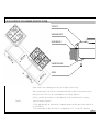
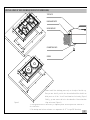
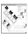
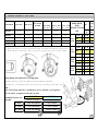
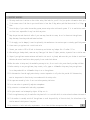
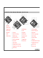
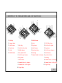
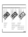
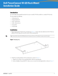
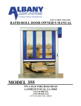
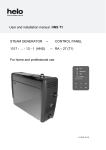
GB
BUILT-IN / TABLE
TOP HOB
GAS COOKER
USER MANUAL
Dear Costumer,
It is our ultimate desire that you achieve the best performance from our product,
which has been passed through meticulous quality control
checks and is manufactured in modern facilities.
Pieces of packaging (plastic bags, polystyrene etc.) must not be left within
reach of children, as they are potentially dangerous. Please dispose of
packaging thoughtfully by the appropriate means.
To this effect, we recommend that you read the entire guide carefully before operating th
keep it as a reference.
ATTENTION!
THIS APPLIANCE SHALL BE INSTALLED IN ACCORDANCE WITH THE REGULATIONS IN
FORCE AND ONLY USED IN A WELL VENTILATED LOCATION. READ THE INSTRUCTIONS
BEFORE INSTALLING OR USING THIS APPLIANCE.
CONTENTS
1. INDEX
6. USING
2. INSTALLATION
OF YOUR COOKER
3. TECHNICAL
FEATURES OF YOUR COOKER
4. IMPORTANT
WARNINGS
5. DESCRIPTION
COOKER SECTION
7. MAINTENANCE
and CLEANING
OF COOKER & CONTROL PANELS
1
2 - INSTALLATION OF YOUR COOKER
ELECTRICAL CONNECTION and SECURITY
Your cooker requires a 13 or 16 Amp fuse. If necessary, installation by a qualified electrician is
1.
recommended.
with 230Volt AC, 50 Hz (for SA will be 220-240V,50-60 Hz), electrical supply, and requires a 16 Amp (for
2. England 13 Amp) fuse. If the mains are different from this specified value, contact an electrician or your
authorised service.
3. Electrical connection of the hob should only be made using sockets with Earth system installed (for England
B.S. Approved sockets with Earth system), and in compliance with Regulations. If there is no proper socket
with Earth in place, immediately contact a qualified electrician. The Manufacturer will not be responsible
for damage or injuries that can arise because of inappropriate supply outlets with no earth system.If the
ends of the electrical connection cable is open, according to the appliance type, make a proper switch
installed in the mains by which all ends can be disconnected in case of connecting / disconnecting from / to
If your electric supply cable gets defective, it should definitely be replaced by the authorized service or
4.
qualified
electricians in order to avoid from the dangers.
5. Electrical cable shouldn't touch the hot parts of the appliance.
GAS CONNECTION and SECURITY
1. Fit the clamp to the hose. Push one of the hose until it goes to the end of the pipe
by heating in boiling water, and tighten the clamp with screw driver.
2. For soundness testing; ensure that the gas controls are closed,
3. Apply only Approved Leak Detection solutions to the connections for leaks.
4.
If the hob is installed above a cupboard or openable drawer, a heat protection panel must be installed under
the hob with a minimum 15 mm clearance.
Caution! Make the oven connection to the gas inlet valve,the hose length must be short and be sure that there is no leakage.
sholud not be longer than 125 cm for safety.
RE-INSPECT THE GAS CONNECTION.
DO NOT MAKE GAS HOSE and ELECTRICAL CABLE OF YOUR COOKER GO THROUGH THE HEATED AREAS,
SPECIALLY THROUGH THE REAR SIDE OF THE COOKER. DO NOT MOVE GAS CONNECTED COOKER. SINCE THE
FORCING SHALL LOOSEN THE HOSE, GAS LEAKAGE MAY OCCUR.
2
2 - IN S TALLATION OF YOU R COOKER (F OR B U ILT-IN HOB )
TOP PLATE
UNLEAKAGE PASTE
WORK SURFACE
CONNECTION CLIPS
SCREW
Please install the unleakage paste strip to the edge of the hob top.
Then you must install your hob into the worksurface.After should cut the paste by knife
which parts out of hob. You will see dimensions for housing (Figure 1)
Finally, you must secure the hob to the underside of the worksurface with connection
Figure-1
clips and screws (Figure-2)
1- This appliance must be installed by a competent person and with particular attention to
air circulation.
2- The housing must be heat resistant to a temperature of 95 °C as per EEC directives
3
2 - IN S TALLATION OF YOU R COOKER (F OR B U ILT-IN D OMIN O HOB )
TOP PLATE
UNLEAKAGE PASTE
WORK SURFACE
CONNECTION CLIPS
SCREW
Please install the unleakage paste strip to the edge of the hob top.
Then you must install your hob into the worksurface.After should cut the pa
which parts out of hob. You will see dimensions for housing (Figure 1)
Finally, you must secure the hob to the underside of the worksurface with c
Figure-1
clips and screws (Figure-2)
1- This appliance must be installed by a competent person and with particular attention to
air circulation.
2- The housing must be heat resistant to a temperature of 95 °C as per EEC directives
4
2 - IN S TALLATION OF YOU R COOKER (F OR B U ILT-IN S ECU RITY HOB )
Hob glass surface
Assembly sponge
Worktop
56
0m
m
48
6m
m
Assembly clips
56
0m
m
m
48
6m
Assembly screw
80
6m
m
m
48
6m
Figure-2
Please stick the sponge strip to the under-edges of the hob top.
Then you must install your hob into the worksurface. You will see
dimensions for housing (Figure 1) Finally, you must secure the hob to
the underside of the worksurface with connection clamps and screws (Figur
Figure-1
1- This appliance must be installed by a competent person and with particular attention to
air circulation.
2- The housing must be heat resistant to a temperature of 95 °C as per EEC directives
5
3 - TECHNICAL FEATURES OF YOUR COOKER
SPECIFICATIONS
OUTER WIDTH
OUTER DEPTH
OUTER HEIGHT
SUPPLY VOLTAGE
HOT PLATE 145 mm
BUILT-IN HOB
TABLE TOP HOB
BUILT IN GLASS
HOB DOMINO
580 mm
580 mm
520 mm
BUILT-IN GLASS
HOB
60 cm
BUILT-IN
GLASS BUILT-IN
GLASS
HOB
70 cm
HOB
90 cm
520 mm
520 mm
520 mm
BURNER INJECTOR
Natura
LPG
VALUES
l Gas
ACCORDING TO THE GAS
G 30-30 G 20-20
TYPE
mbar
1000 W (opt)
510 mm
1000 W (opt)
300 mm
-
590 mm
-
690 mm
-
mbar
mm
KW
KW
0.85
1.15
3.000
0.236
2.770
0.253
Injector
Wok
Power
Burner
Gas Flow
mm
0.96
1.30
KW
4.000
3.660
KW
0.315
0.332
Injector
Medium
Burner Power
Gas Flow
Injector
Small
Burner Power
Gas Flow
mm
KW
KW
mm
KW
KW
Injector
85 mm
105 mm
116.5 mm
116,5 mm
116,5 mm
116,5 mm
Power
Big
220-240V , 50-60 Hz
220-240V , 50-60 Hz
220-240V , 50-60 Hz
220-240V , 50-60 Hz
220-240V , 50-60 Hz
220-240V , 50-60 Hz Burner Gas Flow
510 mm
860 mm
-
To adjust your oven acc. to the gas type, make the adjust. for reduced flame carefully by turning with a
small scredriver as shown below on the scr.in the mid. of the gas cocks as well as nozzle changes.
0.65
0.97
1.780
0.140
1.780
0.167
0.50
0.72
0.88
0.070
0.990
0.092
Before making the connections of the appliance
appliance carefully. In this user Manual, there are important information
regarding your, our customers security, how you will use it and how you will make its maintenance.
Note :
Some of the features specified in the Manual may not be
available in your appliance.
This user manual is prepared for more than one model.
Recommended Flame Gas Cock
Adjustment:
G30èG20,G25
From LPG to Nat.gas
G20,G25èG30
from Nat.gas to LPG
Big Burner
3 turns anticlockwise
3 turns clocwise
Med. Burner
2,5 turns anticlockwi
2,5 turns clockwise
Small Burner
2 turns anticlockwise
2 turns clockwise
6
3 - TECHNICAL FEATURES OF YOUR COOKER (DOMINO HOBS)
DOMINO SINGLE
GAS HOB
DOMINA DOUBLE
GAS HOB
DOMINO DOUBLE
ELECTRIC HOB
OUTER WIDTH
580 mm
580 mm
580 mm
OUTER DEPTH
510 mm
510 mm
510 mm
OUTER HEIGHT
110 mm
110 mm
110 mm
SPECIFICATIONS
SUPPLY VOLTAGE
220-240V, AC 50-60 Hz220-240V, AC 50-60 Hz 220-240V, AC 50-60 Hz
HOT PLATE 145 mm
-
-
1000 W (opt)
HOT PLATE 180 mm
-
-
1500 W (opt)
BURNER INJECTOR VALUES
ACCORDING TO THE GAS TYPE
LPG
Natural Gas
G 30-30 mbar G 20-20 mbar
Big
Power
Burner Gas Flow
mm
KW
KW
0.85
1.15
3.000
0.236
2.770
0.253
Injector
mm
0.96
1.30
KW
4.000
3.660
Gas Flow
KW
0.315
0.332
Injector
mm
KW
KW
0.50
0.72
0.88
0.070
0.990
0.092
Injector
Wok
Power
Burner
Small
Power
Burner
Gas Flow
7
4 - IMPORTANT WARNINGS
1. The setup conditions is written on the sticker rating label and also you will find your product information about gas type (LP
If the current rate of the fuse in your installation is less than 16 Amp, make a qualified electrician fit a 16 Amp
2.
fuse.
3. Since the plug of your cooker has earthing system, ensure using socket with erarth system. If it is used without earth system,
our firm is not responsible for any loss which may arise
4. Keep the gas hose and electrical cable of your oven away from the hot areas, do not let them touch the appliance.
Keep them away from sharp sides and heated surfaces.
5. If the supply cord is damaged, it must be replaced by the manufacturer its services agent or simulary qualified persons in ord
6. Please connect your appliance with a suitable main valve
7. Connect your cooker to LPG or NG cock in shortest way and without any leakage. Min. 40 cm Max. 125 cm
8. When making gas leakage check, never use any flame type like those of lighter, matches, cigarette fire or similar ones.
9. Usage of your appliance creates moisture and heath in the room it is placed, make sure that your kitchen is ventilated well.
Maintain the natural ventilation ducts properly Or use cooker hood devices
10. When the cooker is being used, the reachable parts may be hot, Do not touch to hot parts directly and keep children
11. Before starting to use your appliance, keep curtain, tulle, paper or inflammable things away from your appliance.
Do not keep combustible or inflammable things in or on the appliance.
12. For disconnection from the supply mains having a contact seperation in all poles that provide full disconnection,
must be incorporated in fixed wiring in accordance with the wiring rules.
13. Gas tapes are secured by locks. Do not turn before pressing the button.
14. Do not use cooker in potentially explosive atmospheres.
15. Pay attention to minimum health and safety requirement.
16. The glass ceramic can be damaged by objects falling onto it.
17. Built-in appliances may only be used after they have built in to suitable built-in units and work surfaces that meet standards
18. If the surface is cracked, switch off the appliance to avoid the possibility of electric shock, for hob surfaces of glass cera
similar material which protect live parts
19. Pay attention to health and safety requirements – do not leave children un-supervised when cooking.
8
5 - DESCRIPTION OF THE COOKER AND CONTROL PANEL (FOR BUILT IN GLASS HOB)
4
2 3
4 5
6 7 8
9
1
2
1
4
3
4 5
3
1
6
7
5
9
6
7
8
9
3
4
5
6
2
5
8
6 7 8
5
4
3
2
3
2
2
1
1. Command Knobs
8
7
6
2. Bottom cover
1
1
1. Command Knobs
3. Round frame
1. Command knobs
1. Bottom cover
2. Middle burner
4. Burner grids
2. Bottom cover
2. Glass hob surface
3. Burner grids
5. Middle burner
3. Round frame
3. Command Knobs
4. Glass hob surface
6. Middle burner
4. Burner grids
4. Small burner
5. Bottom cover
7. Wok burner
5. Small burner
5. Big burner
6. Big burner
8. Small burner
6. Big burner
6. Burner grids
7. Middle burner
9. Big burner
7. Wok burner
8. Small burner
8. Middle burner
9. Middle burner
9
5 - DESCRIPTION OF THE COOKER AND CONTROL PANEL (FOR BUILT IN HOB)
1
7
2
3
4
5
6
5
1
1
2
3
4
5
6
4
3
2
6
5
6
1
2
7
3
7
8
8
9
10
11
1. Hob body
2. Bottom cover
3. Command knobs
11
10
9
8
4. Small burner
1. Middle burner
1. 1000 W hotplate
2. Grids
2. Grid for Hot plate
5. Big burner
1. Hob body
3. Big burner
3. Big burner
6. Grids
2. Grid for Hot Plate
4. Small burner
4. Grid for gas burners
7. Middle burners
3. Middle burner
5. Ignition button
5. Small burner
4. Hot plate 1000 W
6. Hob body
6. Ignition button
5. Grid for gas burners
7. Command knobs
7. Hob body
6. Big burner
8. Bottom cover
8. Command knobs for burners
7. Small burner
8. Command knobs for burners
9. Command knob for Hot Plate
9. Command knobs for HP
10. Signal lamp
11. Bottom cover
10. Signal lamp
10
5 - DESCRIPTION OF THE COOKER AND CONTROL PANEL (FOR TABLE TOP HOB)
1
6
5
2
3
4
5
4
1
1
4
3
2
2
3
4
5
6
5
6
1
6
7
7
2
8
9
10
3
10
9
8
1. Hob body
7
2. Command knobs
1. Middle burner
2. Grids
1. 1000 W Hot plate
3. Small burner
1. Hob body
3. Big burner
2. Grid for Hot plate
4. Big burner
2. Grid for Hot plate
4. Small burner
3. Big burner
5. Grids
3. Middle burner
5. Ignition button
4. Grid for gas burners
6. Middle burners
4. Hot plate 1000 W
6. Hob body
5. Small burner
5. Grid for gas burners
7. Command knobs for burners
6. ıgnition button
6. Big burner
7. Hob body
7. Small burner
8. Command knobs for burners
8. Command knobs for burners
9. Command knobs for Hot plate
9. Command knob for Hot plate
10. Signal lamp
10. Signal lamp
11
5 - DESCRIPTION OF THE COOKER AND CONTROL PANEL (FOR CLASIC TABLE TOP HOB)
3
t
4
4
t
5
67
56
56
7
89
3
7
2
8
1
10
4
3
2
1
11
1. Command knobs for burners
8
9
2
1
1. Ignition button
2. Hob body
1. Ignition body
2. Command knobs for gas burners
3. Big burner
2. Command knobs for gas burners
3. Hob body
4. Middle burner
3. Command knob for Hot plate
4. Big burner
5. Middle burner
4. Hob body
5. Middle burner
6. Grids
5. Grid for gas burners
6. Middle burner
7. Hose entry
6. Big burner
7. Grids
8. Small burner
7. Hot plate 1000 W
8. Hose entry
8. Middle burner
9. Small burner
9. Grid for Hot plate
10. Hose entry
11. Small burner
12
5 - DESCRIPTION OF THE COOKER AND CONTROL PANEL (FOR DOMINO BUILT-IN HOB)
2
3
4
5
1
2
3 4
5
1
6 7
2 3 4 5
6
7
1
1. Hob bottom cover
1. Hob bottom cover
1. Hob bottom cover
2. Hob top plate
2. Hob top plate
2. Hob top plate
3. Command knob
3. Command knob for auxiliary 3.
burner
Signal lamp
4. Hob grid
4. Command knob for rapid burner
4. Command knob for small hot plate
5. Wok burner
5. Auxiliary burner
5. Command knob for big hot plate
6. Rapid burner
6. Hot plate 1000 W (Rapid 1500 W)
7. Hob grid
7. Hot plate 1500 W (Rapid 1500 W)
13
6 - USING COOKER SECTION
Using Gas Burners :
In order to obtain maximum output, be careful that the saucepan which will be used should be flat bottomed, and use the saucepans
with dimensions given herein belove. The valves controlling the gas cookers have special security mechanism. In order to light the cooker;
Large Cooker
Normal
24 - 28 cm
Cooker 18 - 22 cm
Aux. Cooker
12 - 18 cm
1. Always press on the switch forward and bring it to flame symbol by turning anticlockwise (left).
All of the lighters shall operate and the cooker you controlled shall light only. Keep the switch pressed until
ignition is performed. (OPTION)
2. Press on the lighter button by pressing on the switch forward and turning anticlockwise (left).
Closed
Fully Open
Half Open
It means Closed Position.
Flame is extinguished
* In models with Gas Security System, when flame of the cooker is extinguished, control valve cuts off the gas automatically. (OPTION)
Using Electric Hotplates :
Make adjustment by rotating the switch clockwise according to the heat level you wish to use for your electric cooker. When the
warning lamp lights over the switch, this means that the cooker is engaged. When the cooking is over bring it back to
145
145
145
180
LEVEL 1
mm
95 W
mm Rapid
135 W
mm Domino
250 W
mm Domino
500 W
Heating - at low cooking
temperature
** Electric Hotplates
LEVEL 2
155 W
165 W
750 W
1000 W
LEVEL 3
LEVEL 4
250 W
250 W
1000 W
1500 W
at normal cooking
temperature
400 W
500 W
LEVEL 5
650 W
750 W
LEVEL 6
1000 W
1500 W
Frying
have standard of 3 or 6 temperature levels (as described herein above).depending on your cooker
maximum temperature.
When using first time, operate your electric hotplate
position.
model that you can use from
in position 3 for 5 minutes. This will make the agent on your hotplate which is sensitiv
Use flat bottomed saucepans which fully contact with the heat as much as you can, so that you can use the energy more productively.
Using Burners :
The our gas ovens top and bottom burner working system is one by one. When you want use your preference burner, before you must make
press the tap knob and wait nearly 5-10 second. Then you can to inflame trought with automatic ignition or match. You must wait a few second
after the inflame to have press by tap knob and after you can make allow the knob. İf you can not made this operation you must try again.
Do not ignite more than 15 second. After 15 second if the burner does not operate than stop the ignition and wait minimum 1 minute before
try If the burner extinguised
because of again.the any reason close the gas control valve and wait minimum 1 minute
in order to operate again.
Using Burners with Flame Failure Device fitted :
Select the burner required, depress and turn the gas control to maximum flame, hold down for 10 to 15 seconds.
once the flame is established the control knob can be released
If the burner fails to stay lit, repeat the procedure, but increase the length of time the control knob is held down.
14
7 -
MAINTENANCE and CLEANING
1. Disconnect the plug supplying electricity for the cooker from the socket and cutoff the gas by closing the gas valve.
2. While cooker is operating or shortly after it starts operating, it is exteremely hot. You must avoid touching heating
3. Never clean the interior part, panel, grids, burner cover and all other parts of the cooker by the tools like hard br
mesh or knife. Do not use abrasive, scratching agents and detergents.
4. After cleaning the interior parts of the cooker with a soapy cloth, rinse it and then dry thoroughly with a soft clot
5. Do not clean your cooker with steame cleaners.
6. Wash the heads of the burners sometimes with soapy water and clean the gas ducts by means of a brush.
7. Never use inflammable agents like acid, thinner and gasoline when cleaning your oven.
8. Do not splash water onto the cooker.
9. Clean removable burner parts with a hot soap solution. Do not clean in the dishwasher.
10. Do not immerse burners or pan rests in water while they are still hot
15