1
LLC “Chelenergopribor”
Small-size portable micro-ohmmeter
IKS–5
User Manual
Certificate
Chelyabinsk
Russia
2015
The manual instructs the user on technical characteristics, list of components, operational principle, and working instructions for the small-size portable microohmmeter IKS–5 (further referred to as IKS–5).
It also offers description of design, operational principle, characteristics of the
device, its components and directions necessary for competent use of IKS–5 (functional use, technical maintenance, current repairs, storage and transportation), as well
as troubleshooting instructions and reclamation of the device and its components.
Abbreviations list:
CP – current probes;
PP – potential probes;
LCD – liquid crystal display;
ADC – analog digital converter;
REF – reference voltage source.
2
1. Description and operation
1.1. Application
1.1.1. The device IKS–5 is used for operative measurement of low electrical resistance to continuous current including intermediate resistance of high voltage breakers
and disconnectors.
The device IKS–5 also allows measure electrical resistance of low inductance circuits of other devices and mechanisms in the range of 0 – 10,000 microohm.
1.1.2. The device can be used at power engineering enterprises, power plants and
substations, as well as at traction substations for electrical transport.
1.1.3. The device operates under the following conditions:
Operating conditions:
• ambient temperature, °C...................................................................... –20…55;
• relative humidity, % .........................................................................90 at 30°C;
• atmospheric pressure, kPa ................................................................ 84…106.7;
• electrical field strength with the frequency of 50 Hz up to 5 kV/m.
• magnetic field strength with the frequency of 50 Hz up to 400 A/m.
Standard conditions:
• ambient temperature, °C...........................................................................20±5;
• relative humidity, % .............................................................................. 30…80;
• atmospheric pressure, kPa ............................................................... 84…106.7;
• voltage of alternating current supply main, V at the frequency of 50 Hz220±20.
1.1.4. The device IKS–5 has a self-contained power supply using the accumulator battery 6 V with nominal capacity not less than 1.2 А«h and alternating current circuit with the voltage of 220 V and frequency of 50 Hz through in-service charging and
feeding device.
1.1.5. Measured resistance value is displayed visually using the four-digit system.
3
1.2. Technical characteristics
1.2.1. The range of measured electrical resistance is 0…10,000 microohm.
1.2.2. Admissible basic relative error of measurements should not exceed:
………………………….. ± (0.2+0.01(10000/R–1))%,
where: R – measured resistance value, microohm.
1.2.3. Admissible additional relative error of measurements in case of change in
ambient temperature from normal to limit values in the temperature operating range
should not exceed the limit of admissible basic error (± (0.5+0.01(10000/R–1))%,
where: R – measured resistance value, microohm) for every 10 °C.
1.2.4. Admissible additional relative error of measurements in case of presence of
the outer magnetic field with the frequency of 50 Hz and intensity of up to 400 A/m
should not exceed the limit of admissible basic error (± (0.5+0.01(10000/R–1))%,
where: R – measured resistance value, microohm).
1.2.5. Device input resistance, not less than: ..................................... 9 kОhm
1.2.6. Length of long measuring cables: ................................................. 12 m
1.2.7. Length of short measuring cables: .................................................. 3 m
1.2.8. Resistance of current measuring cables not more than........... 0.3 Ohm
1.2.9. Device overall dimensions .........................................145х102х55 mm
1.2.10. Mass without measuring cables, not more than ........................ 0.9 kg
1.2.11. Time used for a single measurement, not more than ......................2 s
1.2.12. Transition time for the operational regime, not less than ...............5 s
1.2.13. Time interval between measurements, not less than.......................5 s
1.2.14. The device IKS–5 possesses heat resistant, cold resistant and wet strength
characteristics; besides, it has increased durability during transportation according to
GOST.R 22261-94 for measurement devices of the 4th category.
1.2.15. Unit cost of the minimum control character at measured electrical resistance less than 1000 microohm: ........................................................0.1 microohm
4
1.2.16. Unit cost of the minimum control character at measured electrical resistance of 1,000 microohm and more:.....................................................1 microohm
1.2.17. Accumulator charge period, not more than........................... 15 hours
1.2.18. Average service period of the device, not less than ..............10 years
1.2.19. Average error-free running time, not less than ....................... 3,000 h
1.3. The device IKS–5 components
1.3.1. The device has a rectangular design and the transportation belt and connectors for connection of connecting wires and charging and feeding device. There is a
display window, power supply switch and «Пуск» ("Start") control button at device
facial surface. The device consists of the following components:
• Measuring device ....................................................................................1 piece
• Long measuring cables.......................................................................... 2 pieces
• Short measuring cables ......................................................................... 2 pieces
• Kelvin clamp probes of the "crocodile" type ........................................ 2 pieces
• Kelvin pin probes ....................................................................................1 piece
• Power supply - charging device ..............................................................1 piece
• User Manual ............................................................................................1 piece
1.3.2. The device is used for the following purposes:
• To generate steady measuring current.
• To amplify and transform the signal recorded from potential probes into digital
code.
• To display measured resistance value.
1.3.3. The accumulator battery is used to supply power to the device and is installed inside the device frame.
1.3.4. The power supply - charging device is used to charge the device accumulator and supply power to the device in case of absence of the accumulator or in case of
accumulator discharged state. It is designed as a connector assembly rated for 220 V
and is connected to the measuring device by a connecting cord. There is a light5
emitting diode indicator for display of accumulator charge process on the device
frame.
1.4. Design and operation
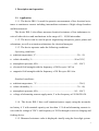
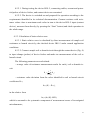
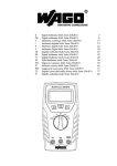
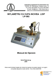
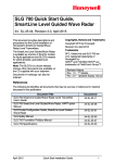
1.4.1. Fig. 1 shows the flow chart of the device.
Fig.1
1.4.2. Single functional schematic blocks are used for the following. ADC amplifies voltage at potential probes (PP), converts a signal into digital additional code and
transmits it to the microcomputer on demand for further processing. ADC has a builtin digital filter used to dejam noises caused by commercial nets with the frequency of
50 Hz. Steady continuous current generator is used to generate current equal to about 2
A through current probes (CP) during measurement. A single-chip microcomputer is
used to control the device, control button and ADC, it switches on the steady current
generator and displays indicated values. The microcomputer has nonvolatile data
memory with calibration factors calculated during device adjustment. (see 3.2).
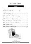
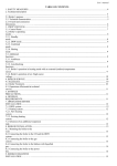
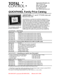
The circuit of measuring current rise is separated from the circuit of potential
drop measurement by electrical isolation at transistor optocoupler. The device is lo-
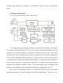
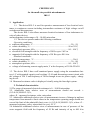
6
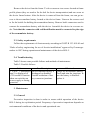
cated in the welded frame made from aluminum alloy. Fig. 3 gives the image of the
clamp.
PP
CP
Connector
Fig. 3
1.4.3. The device measures resistance using standard four-point method. Steady
current with known intensity passes through current probes (CP) along the controlled
area during the measurements. Voltage generated in the circuit controlled area by the
above-mentioned current using potential probes (PP) is supplied to the device input.
1.4.4. The operating algorithm of the device at the moment of measurements is
given below. After having installed the probes at the device current-carrying parts, the
operator presses the "Start" button. The microcomputer measures schematic zero shift
and starts the ADC. After the zero shift code is supplied from the ADC, the microcomputer starts the steady continuous current generator and transmits the command to start
the ADC after ten milliseconds. After ADC operational regime is over, the microcomputer receives the code proportional to the input signal and switches off the current
generator. Using the code proportional to the signal at potential probes and zero shift
code of the measurement schematic, the microcomputer does the correction and displays the measurement results.
1.4.5. Device circuit technique allows exclude the additive component of systematic inaccuracy according to the reference standard method and measure schematic
zero shift before each measurement.
Non-linearity of the device scale is mainly determined by ADC non-linearity and
is equal to not more than ±0.015% from the full scale.
7
The above-mentioned features of mathematical treatment increase measurement
accuracy, simplify use of the device under industrial conditions and reduce requirements to professional skills of the maintenance staff.
1.5. Measuring tools, instruments and accessories
The list of specific measuring tools, testing and other equipment, instruments and
accessories required for control, adjustment, maintenance and current repairs of the
device IKS–5 and its components is given in Table 1.
Table 1. List of specific measuring tools, testing and other equipment, instruments and accessories
Main technical (and metrologiQuanName
cal) characteristics
tity
1. Clamp probes of the
130х56х26 mm
2
"crocodile" type
2. Power supply - charging The "Operation" regime 6.9 V, 2
device
A
1
The "Charging" regime 0.06 A
3. Short connecting cable
2
3
0.2 m
4. Long connecting cable
2
12
0.5 m
5. Resistance standard
6. Resistance standard
7. Resistance standard
8. Resistance standard
100 micro-ohm
(accuracy better than 500 ppm)
1000 micro-ohm
(accuracy better than 100 ppm)
10 000 micro-ohm
(accuracy better than 100 ppm)
25 micro-ohm
(accuracy better than 5000 ppm)
9. Contact device
10. Screwdriver
1
1
1
1
1
1
1.6. Identification marks
1.6.1. Identification marks for the device IKS–5 match the requirements of
GOST.R 22261-94 and GOST.R 26104-89.
1.6.2. Each device IKS–5 is identified by:
– name of the device;
8
– serial number according to the numeration system of the manufacturing enterprise;
1.6.3. Identification is executed in any manner provided it is legible and undamaged during the whole period of device IKS–5 service life.
1.7. Packing
1.7.1. Packing of the device IKS–5, its manual, accompanying documents and
used auxiliary tools match the requirements of GOST.R 9181-74.
2. Device application
2.1. Pre-starting procedure and operation
2.1.1. One should fulfill the following steps before starting the device:
• Study the manual, certificate, device schematic and design.
• Check the device IKS–5 visually.
• Connect measuring cables of required length to the device and feelers by means of
corresponding connectors.
2.2. Device IKS–5 operation
2.2.1. To make measurements using the device IKS–5 one should do the following.
2.2.1.1. Switch on the "On/Off" power supply switch located on the device
front panel. After the switch is in the "on" position, the ADC is self-calibrated accompanied by countdown at the display during 5 seconds. After self-calibration is over, the
display shows 00, which means that the device can be used to make measurements.
2.2.1.2. The clamps are placed onto current-carrying parts of the investigated
object – switches or disconnectors - and are shook a little in order to improve contacts
between the object and probes. To reduce influence of electromagnetic disturbances
9
onto measurement results, one should intertwist the measuring cables (this should necessary be done in case one uses long measuring cables).
2.2.1.3. To start the measurement, press the «Пуск» ("Start") button. Measurement results are displayed on the device. If the measurement value does not exceed
11,000 microohm, it can be shown at the device display. In this case the display highorder digit is a hexadecimal number: A=10, b=11, correspondingly. If the measured
resistance is much more than 11,000 microohm, the display shows overflow "ПЕР".
2.2.1.4. Read the measurement result from the display.
2.2.1.5. Next measurement can be started not earlier than four seconds after the
previous one. During this time period the «Пуск» ("Start") button is disabled. The end
of the period is indicated by a short-term lighting of the decimal point after the number
of the high-order (leftmost) digit of the display.
2.2.1.6. In order to save power supply stock, switch off device power supply
system, if time interval between measurements exceeds 5 min.
2.2.2. It is prohibited to switch on and operate the device, if the display shows
“РАЗР” (Discharged state), which means that the accumulators are discharged. Charge
the accumulators.
2.2.3. In case of absence or discharged state of the accumulators, one can make
measurements using the alternating current circuit of 220 V, 50 Hz – connect the
power supply - charging device to the device IKS–5 using the connector and plug it
into the circuit, then make measurements according to par. 2.2.1. of the manual.
2.2.4. Charge the accumulators when device power is off. Insert the connector
plug of the power supply - charging device into the charge connector hole located at
the right sidewall of the device frame. Plug the bracket located in the charging device
frame into the socket with the parameters 220 V, 50 Hz. Time required for accumulator charging in case of complete discharge should not exceed 15 hours.
2.2.5. To replace the accumulators in case of breakdown resulting from termination of life time or for any other reasons do the following.
10
Remove the device from the frame. To do so unscrew two screws located at frame
profile planes (they are used to fix the belt for device transportation) and one screw at
the device frame bottom. After the device is removed from the frame, one can get access to the accumulator battery located at the device frame. Unscrew the screws used
to fix the buckle for holding the accumulator battery. Remove knife connectors used to
connect the accumulator battery with the device. Assemble the device in a reverse order. Note that the connector with red identification mark is connected to plus sign
of the accumulator battery.
2.3. Safety requirements
Follow the requirements of electrosecurity according to GOST.R 12.3.019-80 and
“Rules of safety engineering for use of electric installations” approved by Gosenergonadzor in 1997 during operation and maintenance of the device IKS–5.
2.4. Troubleshooting
Table 2 shows some possible failures and methods of maintenance.
Table 2. Possible failures
Failure
1. “РАЗР” (“Discharged
state”) is displayed or
LCD wouldn’t function
when one switches on
power supply or during
operation.
Possible origin
The accumulator battery is
discharged or disabled.
Possible oxidation of battery connector junctions.
What to do
Charge the accumulator battery.
Check and trim the junctions. In
case the battery is disabled –
replace it.
3. Maintenance
3.1. General
Preventive inspection is done in order to ensure stable operation of the device
IKS–5 during its exploitation period. Frequency of preventive inspections depends on
environmental conditions of the device and operational rate.
11
Routine maintenance connected with device opening is combined with any repairs
or device regular calibration.
Recommended methods and terms of preventive inspection:
- visual examination and external cleaning – on monthly basis.
- internal examination, examination of technical parameters of device mechanical assemblies – on annual basis.
For inner inspection unscrew two screws located at frame profile planes (they are
used to fix the belt for device transportation) and one screw at the device frame bottom. After the device is removed from the frame, one can get access to the accumulator
battery. Check reliability of inner mechanical connections and tighten them if necessary. Assemble the device in a reverse order.
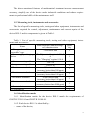
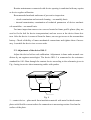
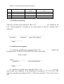
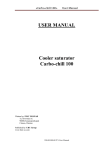
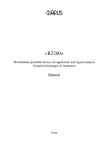
3.2. Adjustment of the device IKS–5
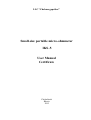
Adjust the device before each calibration. Adjustment is done under normal conditions by an engineer-metrologist. The device IKS–5 is connected to the resistance
standard for 0.01 Ohm through the contact device according to the schematic given in
Fig. 4 using in-service short measuring cables with probes.
1
U
U
I
I
2
Fig. 4
1 – contact device – plate made from insulation material with metal isolated contact
plates with flexible current outlets for connection to measuring resistor fixed on the
surface of the plate.
12
2 – resistance coil (measuring resistor) with potential (U) and current (I) clamps.
After switching on the device power wait five minutes so that the device warms
up. After the device is warmed up, press the «Пуск» (“Start”) button and after the display shows the data, press the «Пуск» (“Start”) button five times successively and
hold it pressed not less than 1 second. The display would show “Adj”, which means
that the device is in the regime of adjustment. One can see numbers 9999, 8888, …,
0000 on the display before the adjustment procedure. If one presses the “Start” button
when the numbers appear, the device would make one measurement and quit the regime of adjustment. Otherwise adjustment begins and lasts for about 24 seconds. The
adjustment regime stops automatically and is indicated by “End” on the display.
4. Calibration of the device IKS–5
4.1. General
Calibration of the device IKS–5 is done once a year under normal working conditions according to the document CP 25-233-00 “GSI. Small-size portable microohmmeter IKS–5. Calibration procedure” (CP), developed by the Ural ScientificResearch Institute of Metrology.
4.2. Calibration procedure
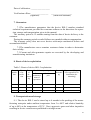
Table 3 gives the description of the calibration procedure for the device IKS–5.
Table 3
№
External examination
Testing
Checking basic relative error
ND Number for
calibration
7.1
7.2
7.3
Procedure for
first calibration
repeating calibration
Yes
Yes
Yes
Yes
Yes
Yes
4.3. Calibration devices
13
For calibration, devices listed in Table 1, par. 5-9 are used. One can also use other
calibration devices with similar metrological parameters.
4.4. Requirements for calibration
4.4.1. To make calibration, one should stick to normal conditions when basic
relative error of the examined device IKS–5 is normalized:
- Ambient temperature............................................................ 20±5°C
- Relative humidity, not more.............................................. 30…80%
- Atmospheric pressure ...............................................84…106.7 kPa
4.4.2. The accumulator of the device IKS–5 should be fully charged before calibration. In case of absence of accumulator, use in-service charging and feeding device
supplied from the alternating current circuit with the frequency of 50 Hz and voltage of
220±20 V.
4.4.3. Before calibration store the device IKS–5 under environmental conditions
mentioned in par. 3.3.4.1. not less than 4 hours.
4.4.4. Before testing, the device IKS–5 should by in an “on” position during the
time period identified in standard-technical documentation for the device.
4.5. Calibration
4.5.1. External examination
Calibrated device IKS–5 should be fully assembled (excluding accessories). The
device IKS-5 should be examined and the following failures should be mended:
- inadequate fixing of connectors, plugs and socking connectors used for connecting external circuits and micro-ohmmeter;
- breakdown in insulation of external current-carrying parts of the device;
- major mechanical damage of device external parts, absence of adjustment
arms.
4.5.2. Testing
14
4.5.2.1. During testing the device IKS–5, connecting cables, current and potential probes of device feelers, and contact device are examined.
4.5.2.2. The device is switched on and prepared for operation according to the
requirements identified in its technical documentation. Connect resistors with resistance values close to maximum scale value in turn to the device IKS–5 input (contact
device), measure them directly (by pressing the “Start” button) and check operation in
the whole range.
4.5.3. Calculation of basic relative error
4.5.3.1. Basic relative error is calculated by direct measurement of sample coil
resistance or branch circuit by the checked device IKS–5 under normal application
conditions.
4.5.3.2. Connect sample coil or branch circuit through the contact device (Fig. 4)
to input clamps (probes) of device feelers and make ten measurements of the coil or
branch circuit.
The following parameters are calculated:
– average value of resistance measurement results for each j coil or branch circuit
Rj =
1 10
∑ Rij ;
10 j =1
– resistance value deviation from the value identified in coil or branch circuit
certificates Rаттj
&cj=|Rj – Rаттj|,
in the relative form
&crj=(&cj/Rj)«100%,
which is assumed to be systematic component of measurement errors of investigated
microhmmeter;
15
– average quadratic deviation (AQD) of measurement results for j coil or branch
circuit
Sj =
1 10
( Rij − Rаттj ) 2
∑
9 j =1
and in relative form
Srj=(Sj/Rj)«100%,
which is assumed to be random component of measurement error of investigated microhmmeter.
4.5.3.3. In case &cj/Sj<0.8, error systematic component is not considered and basic error is calculated as
&j=&js,
where &js=t(0.95,п=9) Sj=2.262 Sj. Here t(P,n) is Student’s coefficient.
4.5.3.4. If &cj/Sj>8, then random error contrary to systematic error is not considered and
&j=&cj.
4.5.3.5. In case the equations 4.5.3.3 и 4.5.3.4 are not satisfied, error value for
investigated microhmmeter is calculated as
&j=Kj«S5j
where Kj – coefficient depending on ratio of error random and systematic components;
S5j – mean-square deviation value of the sum of error random and systematic components.
The value is calculated as
S Σj = S c2j + S 2j + S ок2 j ,
Device IKS–5 zero shift is calculated by making measurements when the two device IKS–5 feelers are connected to one broad couple of contact plates.
The device IKS–5 is serviceable if basic relative error value does not exceed that
in par. 1.2.2.
16
5. Current repairs
Current repairs are executed by the manufacturing enterprise.
6. Transportation and storage
6.1. The device IKS–5 can be stored up to 6 months in the packing of the manufacturing enterprise under ambient temperature from 5 to 40С and relative humidity
of up to 80% at the temperature of 25С. Dust, aggressive gases and other impurities
resulting in device corrosion are prohibited in storage rooms.
In case of the device IKS–5 long-term storage, it is recommended to store charged
accumulators outside the device frame. It is prohibited to store the device in switched
on state.
6.2. Transportation methods of the device IKS–5 should match GOST.R 2226194.
Transportation conditions for the device IKS–5 with respect to mechanical and environmental factors should not exceed the following values:
1) impact loads:
- max. acceleration 30 m/s2;
- number of impacts per minute from 80 to 120;
- exposure time 1 h
2) high temperature 50C;
3) low temperature minus 50C;
4) relative humidity 98% at 35C;
5) atmospheric pressure 86…105 kPa.
6.3. Environmental influence onto the device IKS–5 under extreme conditions of
transportation should match the storage requirements 3 or 5 of GOST.R 15150-69.
17
7. Reclamation
Reclamation procedures for the device IKS–5 match the requirements and instructions of the consumer enterprise. Reclamation procedures for the accumulators match
the requirements of the accumulator manufacturing enterprise.
18
CERTIFICATE
for the small-size portable microhmmeter
IKS–5
1. Application
1.1. The device IKS–5 is used for operative measurement of low electrical resistance to continuous current including intermediate resistance of high voltage cut-off
switches and disconnectors.
The device IKS–5 also allows measure electrical resistance of low inductance circuits of other devices
and mechanisms in the range of 0 – 10,000 microohm.
1.2. The device operates under the following conditions:
Operating conditions:
• ambient temperature, °C...................................................................... –20…55;
• relative humidity, % .........................................................................90 at 30°C;
• atmospheric pressure, kPa ................................................................ 84…106.7;
• electrical field strength with the frequency of 50 Hz up to 5 kV/m.
• magnetic field strength with the frequency of 50 Hz up to 400 A/m.
Standard conditions:
• ambient temperature, °C...........................................................................20±5;
• relative humidity, % .............................................................................. 30…80;
• atmospheric pressure, kPa ............................................................... 84…106.7;
• voltage of alternating current supply main, V at the frequency of 50 Hz 220±20.
1.3. The device IKS–5 has a self-contained power supply using the accumulator battery 6 V with nominal capacity not less than 1.2 А«h and alternating current circuit with
the voltage of 220 V and frequency of 50 Hz through in-service power supply - charging device.
1.4 Measured resistance value is displayed visually using the four-digit system.
2. Technical characteristics
2.1 The range of measured electrical resistance is 0…10,000 microohm.
2.2. Admissible basic relative error of measurements should not exceed: ±
(0.2+0.01(10000/R–1))%,
where: R – measured resistance value, microohm.
2.3. Admissible additional relative error of measurements in case of change in ambient
temperature from normal to limit values in the temperature operating range should not
exceed the limit of the admissible basic error (± (0.2+0.01(10000/R–1))%, where: R –
measured resistance value, microohm) for every 10 °C.
2.4.Admissible additional relative error of measurements in case of presence of the
outer magnetic field with the frequency of 50 Hz and intensity of up to 400 A/m
19
should not exceed the limit of admissible basic error (± (0.2+0.01(10000/R–1))%,
where: R – measured resistance value, microohm).
2.5. Device input resistance, not less than: ................................................ 9 kОhm
2.6. Length of long measuring cables: ............................................................ 12 m
2.7. Length of short measuring cables: ............................................................. 3 m
2.8. Resistance of current measuring cables not more than ...................... 0.3 Ohm
2.9. Device overall dimensions ....................................................145х102х55 mm
2.10. Weight without measuring cables, not more than:............................... 0.9 kg
2.11. Time used for a single measurement, not more than: ................................2 s
2.12. Transition time for the operational regime, not less than: .........................5 s
2.13. Time interval between measurements, not less than:.................................5 s
2.14. The device IKS–5 possesses heat resistant, cold resistant and wet strength characteristics; besides, it has increased durability during transportation according to
GOST.R 22261-94 for measurement devices of the 4th category.
2.15. Unit cost of the minimum control character at measured electrical resistance less
than 1000 microohm:.........................................................................0.1 microohm
2.16. Unit cost of the minimum control character at measured electrical resistance of
1000 microohm and more: ...................................................................1 microohm
2.17. Accumulator charge period, not more than...................................... 15 hours
2.18. Average service period of the device, not less than .........................10 years
2.19. Average error-free running time, not less than .................................. 3,000 h
3. Device components
Table 1. Components of the device IKS–5
№
1
2
3
4
5
6
7
Name
Micro-ohmmeter IKS–5
Long measuring cables
Short measuring cables
Clamp probes of the "crocodile" type
Pin probes
Power supply - charging device
User Manual and certificate
Amount
1
2
2
2
2
1
1
4. Conservation
20
Table 2. Conservation of the device IKS–5
Date
Procedure
Period of validity,
years
Position, surname and signature
5. Certificate of packing
Small-size portable micro-ohmmeter IKS–5 № ………………… was packed by the
LLC “Chelenergopribor” according to the requirements of effective technical documentation.
____________
(position)
_____________ __________________
(signature) (name and surname)
_________________
(date)
6. Certificate of acceptance
6.1. Small-size portable micro-ohmmeter IKS–5 № ………………… matches the
requirements of TU 4221.012.34547804-2011 and is serviceable.
Head of QCD
Stamp ________________
(signature)
____________________
(name and surname)
_________________
(date)
6.2. Small-size portable micro-ohmmeter IKS–5. № ………………… was calibrated under the conditions of the manufacture according to CP 25-233-00 “GSI.
Small-size portable microhmmeter IKS–5. Calibration procedure” (CP), and is serviceable.
21
Date of calibration: __________________
Verification officer: ________________
(signature)
____________________
(name and surname)
7. Guarantees
7.1 The manufacturer guarantees that the device IKS–5 matches standard
technical requirements provided the consumer adheres to the directions for operation, storage and transportation given in the manual.
The warranty period is 12 months starting from the date of device delivery to the
customer.
During the warranty period revealed failures are mended without compensation.
The warranty policy does not cover devices with major mechanical defects and
accumulator failures.
7.2 The manufacture can re-examine customer claims in order to determine
their validity.
7.3 Current and after-guarantee repairs are executed by the developing and
manufacturing institution.
8. Route of device exploitation
Table 3. Route of device IKS–5 exploitation
Date of
installation
Place
of installation
Date
Nonfailure operating time
of
From
After last redecommence
pair
mount
ment of
ing
operation
Cause of
demounti
ng
Signature of the person responsible for
installation (demounting)
9. Transportation and storage
9.1. The device IKS–5 can be stored up to 6 months in the packing of the manufacturing enterprise under ambient temperature from 5 to 40С and relative humidity
of up to 80% at the temperature of 25С. Dust, aggressive gases and other impurities
resulting in device corrosion are prohibited in storage rooms.
22
In case of the device IKS–5 long-term storage it is recommended to store charged
accumulators outside the device frame. It is prohibited to store the device in switched
on state.
9.2. Transportation methods of the device IKS–5 should match GOST.R 2226194.
Transportation conditions for the device IKS–5 with respect to mechanical and environmental factors should not exceed the following values:
1) impact loads:
- max acceleration 30 m/s2;
- number of impacts per minute from 80 to 120;
- exposure time 1 h.
2) high temperature 50C;
3) low temperature minus 50C;
4) relative humidity 98% at 35C;
5) atmospheric pressure 86…105 kPa.
9.3. Environmental influence onto the device IKS–5 under extreme conditions of
transportation should match the storage requirements 3 or 5 of GOST.R 15150-69.
10. Reclamation
Reclamation procedures for the device IKS–5 match the requirements and instructions of the consumer enterprise. Reclamation procedures for the accumulators match
the requirements of the accumulator manufacturing enterprise.
Address of the developing and manufacturing institution: LLC “Chelenergopribor”, ul. Severnaya (Shershni), 52, Chelyabinsk, 454902, Russian Federation. E-mail:
[email protected]. Internet: www.limi.ru/en/
Phone/fax +7-351-211-54-01.
23