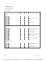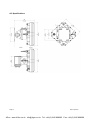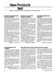
1
Installation and User Manual
Liberator V1000
Revision 1.2
4Gon www.4Gon.co.uk [email protected] Tel: +44 (0)1245 808295 Fax: +44 (0)1245 808299
1 INTRODUCTION ......................................... 1
1.1 Intended users .......................................... 1
1.2 Revision.................................................... 1
1.3 Prior knowledge ....................................... 1
1.4 Warranty .................................................. 1
1.5 Copyright / Disclaimer .............................. 1
2.1 General description .................................. 2
2.1.1 Benefits ............................................... 2
2.1.2 Applications ......................................... 2
2.2 Package contents ...................................... 3
2.2.1 Terminals ............................................. 3
2.2.2 Wall-Mount/Alignment Bracket ........... 3
2.2.3 POE+ Injector ....................................... 3
2.2.4 Mast Bracket........................................ 4
2.2.5 Ice Bridge/Sun-Shield ........................... 4
2.3 Accessories and Spares ............................. 4
2.3.1 Optical Alignment Tool......................... 4
2.3.2 Surge Arrestor...................................... 4
3.1 Terminal location ...................................... 5
3.2 Line of sight .............................................. 5
3.3 Link distance / Link availability .................. 5
Link Distance .................................................. 5
Boundary Diameter ........................................ 5
3.4 TERMINAL MOUNTING OPTIONS ............... 6
3.4.1 Wall mounting ..................................... 6
3.4.2 Pole mounting ..................................... 6
3.5 Cabling ..................................................... 6
3.6 Grounding / Lightning protection .............. 6
3.7 Co-located applications ............................. 6
4.1 Mount installation .................................... 7
4.1.1 Wall mount .......................................... 7
4.1.2 Mast mount ......................................... 7
4.2 Terminal installation ................................. 7
4.3 Cable installation ...................................... 8
4.4 Antenna alignment ................................... 8
4.4.1 Alignment Procedure ........................... 8
Link Distance .................................................. 8
Alignment Accuracy ........................................ 8
4.5 Grounding ................................................ 9
4.6 Lightning / Surge protector ....................... 9
4.7 Power injector .......................................... 9
Terminal .......................................................10
IP Address .....................................................10
Subnet Mask .................................................10
Username .....................................................10
Password ......................................................10
5.1 Web browser interface ............................10
5.1.1 Overview ........................................... 10
5.1.2 Wireless ............................................. 10
5.1.3 Network............................................. 10
5.1.5 Status ................................................ 11
5.1.6 Administration ................................... 11
Object........................................................... 12
OID ............................................................... 12
OID type ....................................................... 12
Description ................................................... 12
A TECHNICAL INFORMATION ...................... 13
A.1 Troubleshooting...................................... 13
A.1.1 Power and network connection ......... 13
A.1.2 Network configuration ....................... 13
A.1.3 Misalignment..................................... 13
General system information .......................... 15
Availability .................................................... 16
Rain zone * ................................................... 16
Link Distance (m) ........................................... 16
A.2.2 RSSI DC Voltage vs Received dBm ......... 17
A.3 ITU Rain Areas ........................................ 18
Map of Americas ........................................ 18
Map of Asia and Australasia ........................ 19
Map of Europe, Middle East and Africa ....... 20
B.1.1 FCC statement ...................................... 21
B.1.2 ETSI Conformity.................................... 21
B.1.4 CE – Declaration of conformity ............. 22
C
CONTACTS ........................................... 23
C.1 Technical assistance ................................ 23
Sub10 Systems Limited........................... 23
4Gon www.4Gon.co.uk [email protected] Tel: +44 (0)1245 808295 Fax: +44 (0)1245 808299
Liberator V1000 Manual
Rev 1.2
1 INTRODUCTION
1.1 Intended users
This manual is intended for all installation and service personnel who are involved in the planning,
installation, operation and maintenance of the Liberator V1000 equipment. Although the Liberator V1000 Link
is designed for easy installation and setup, optimum performance can be achieved by following the
procedures outlined in this manual.
1.2 Revision
Sub10 Systems reserves the right to revise this documentation periodically without any obligation to provide
notification of such revision or changes.
1.3 Prior knowledge
This manual assumes that the installer has at least a basic experience and understanding of networking
equipment, as well as some familiarity with its configuration and operation. The information covered in this
manual should be fully understood prior to installation.
1.4 Warranty
Sub10 Systems warrants to the original end user (purchaser) that this product is free from any defects in
materials or workmanship for a period of up to 24 month (2 Years) from the date of shipment to the end user.
During the warranty period and upon proof of purchase, should the product show indications of failure due to
faulty workmanship and/or materials, Sub10 Systems will, at its discretion, repair or replace the defective
products or components without charge for either parts or labor and to whatever extent it shall deem
necessary to restore the product or components to full operating condition. Any replacement will consist of a
new or remanufactured, functionally equivalent product of equal value, and will be offered solely at the
discretion of Sub10 Systems.
This warranty shall not apply if the product is modified (e.g. warranty seal is broken), misused, tampered
with, damaged by an act of God, or subjected to abnormal working conditions. To obtain services under this
warranty, contact Sub10 System’s Service Centre. Products must be returned postage prepaid. It is
recommended that the terminal be insured when shipped. Any products returned without either proof of
purchase or with an outdated warranty will not be repaired or replaced. The customer will be billed for parts
and labor. All repaired or replaced products will be shipped by Sub10 Systems to the corresponding return
address ‘postage paid’. If the customer specifies an alternative return destination where additional costs are
incurred, the customer shall bear the cost of the additional return shipment cost. This warranty gives you
specific legal rights, and you may also have other rights that vary from state to state.
1.5 Copyright / Disclaimer
Copyright © 2010-2011 by Sub10 Systems
The contents of this publication may not be reproduced in any part or as a whole, transcribed, stored in a
retrieval system, translated into any language, or transmitted in any form or by any means, electronic,
mechanical, magnetic, optical, chemical, photocopying, manual, or otherwise, without the prior written
permission of Sub10 Systems.
Page 1
Sub10 Systems
4Gon www.4Gon.co.uk [email protected] Tel: +44 (0)1245 808295 Fax: +44 (0)1245 808299
2 SYSTEM OVERVIEW
2.1 General description
The Liberator V1000 system operates as a data link in the unlicensed 60 GHz
band between 57 GHz and 64 GHz.
Measuring only 18cm x 18cm (7” x 7”), Liberator V1000 delivers full duplex data
at a rate of up to 1000 Mbps over a distance of up to 800m.(2600 ft)
For more detailed technical data see appendix A.2.
2.1.1 Benefits
•
Easy installation – The concept of the Liberator V1000 Link allows to the end user to install it as easy
as any other network component.
The single cable solution reduces the complexity of the installation. The terminal is connected to the
network, monitored and supplied with power through a single outdoor rated CAT 6 Ethernet cable.
A visual alignment tool together with an alignment bracket allows the user to easily install the
link. Immediate operation without the need for additional configuration is granted.
•
Network performance – Guaranteed full duplex at 1000 Mbps along the complete range. Unlike
typical WLAN equipment the user can transmit a full 1000 Mbps over the link.
•
License free operation – The system has been approved and can be operated in many countries.
•
System administration – To monitor the status and the traffic, the user can access the link statistics
either via the HTML user interface or by integrating it into a network management tool via SNMP.
•
Security – The proprietary radio interface does not allow any other system to access the 60 GHz
transmitted data.
•
A high level of data security is inherent in the product via signal absorption by atmospheric oxygen
and the use of high gain/narrow beam-width antennas.
2.1.2 Applications
•
LAN extension
•
Redundant access
•
Campus connectivity
•
Disaster recovery •Wireless backhaul
•
Centralization of IT infrastructure
•
Temporary connections during events
•
Mesh, hub and spoke configuration
Page 2
Sub10 Systems
4Gon www.4Gon.co.uk [email protected] Tel: +44 (0)1245 808295 Fax: +44 (0)1245 808299
Liberator V1000 Manual
Rev 1.2
2.2 Package contents
A complete link is packed in one box. The box contains the following:
• Terminal A
• Terminal B
• Adjustable Alignment Brackets
• Pole Clamps
• Sealed Ethernet connectors
• Ice bridges /Sun-Shields
• POE+ injectors and leads
• Fixing and accessory kit
2.2.1 Terminals
Each terminal combines the antenna and the transmitter and receiver. Each
terminal is connected to the network via a standard Cat 5e Ethernet cable with RJ45 connectors.
Power is supplied to the terminal through the Ethernet cable. This will require either
compatible network equipment or a POE+ injector.
2.2.2 Wall-Mount/Alignment Bracket
The wall mount bracket facilitates easy radio alignment owing to its independent
axis’s. It has coarse and fine alignment capabilities.
2.2.3 POE+ Injector
The terminal is powered via an Ethernet cable according to the IEEE 802.3at POE+
standard. Should the network equipment connected to the Liberator V1000 Link not
offer POE+, a power injector can be inserted in line with the Ethernet cable.
Page 3
Sub10 Systems
4Gon www.4Gon.co.uk [email protected] Tel: +44 (0)1245 808295 Fax: +44 (0)1245 808299
2.2.4 Mast Bracket
The mast bracket is used to mount the bracket onto a mast. The bracket is
suitable for any pole diameter from 50 mm to 115 mm (2” to 4.5”).
2.2.5 Ice Bridge/Sun-Shield
The ice bridge offers additional protection for the terminal against rain, snow and iceformation
2.3 Accessories and Spares
2.3.1 Optical Alignment Tool
The optical alignment tool provided is easily mounted on the terminal using the locator
pins and large thumbscrew. It enables both ends of the link to be aligned quickly,
simply and independently.
2.3.2 Surge Arrestor
The surge arrestor is placed between the radio head and the Ethernet cable connecting to the POE and any
other network infrastructure. This device helps to reduce the risk of damage from lightning or high tension
overhead equipment. Sub10 do not supply an arrestor but can recommend preferred suppliers.
Page 4
Sub10 Systems
4Gon www.4Gon.co.uk [email protected] Tel: +44 (0)1245 808295 Fax: +44 (0)1245 808299
Liberator V1000 Manual
Rev 1.2
3 SITE PLANNING
All installers must perform a full site inspection and plan carefully prior to the physical installation of a
Liberator V1000 system.
This preparation must include:
• Evaluating the most appropriate location for the installation of the terminal.
• Identifying an appropriate mounting structure (wall or mast) for each terminal.
• Planning the cable routing from the network component to the terminal.
3.1 Terminal location
When selecting the best terminal location the following factors should be considered:
• Accessibility (e.g. roof)
• Type of mounting (e.g. wall or pole)
• Grounding connection point
• Cable runs (max. 100 m / 328 ft)
• Line of sight
3.2 Line of sight
To ensure a clear line of sight, there must be no obstructions between the two terminal locations. The
1
required clearance can be established visually or by using the following table :
3.3 Link distance / Link availability
The link distance is directly related to the weather conditions. The affordable link availability is influenced by
the following environmental conditions:
• Rainfall:- the lower, the better
• Temperature:- the higher, the better
• Air pressure:- the lower, the better
Knowledge of the link distance (line of sight) is important in estimating link quality.
For the rain regions in your country, see appendix A.4.
Link Distance
Boundary Diameter
100 m
(328 ft)
0.7 m
(2.3 ft)
200 m
(656 ft)
1.0 m
(3.3 ft)
400 m
(1312 ft)
1.4 m
(4.6 ft)
600 m
(1968 ft)
1.7 m
(5.6 ft)
800 m
(2625 ft)
2.0 m
(6.6 ft)
Page 5
Sub10 Systems
4Gon www.4Gon.co.uk [email protected] Tel: +44 (0)1245 808295 Fax: +44 (0)1245 808299
3.4 TERMINAL MOUNTING OPTIONS
3.4.1 Wall mounting
The wall mounting location should be strong enough to secure the terminal to the
wall, taking into account all foreseeable environmental conditions (e.g. wind, rain,
ice).
Depending on the material to which the bracket is mounted, differently sized
mounting hardware may be necessary. To mount the terminals onto the bracket use
the enclosed M6 bolts. The bracket allows a tilt angle of +/- 50° in both axis.
3.4.2 Pole mounting
The mast mount bracket will be needed to mount the terminal onto poles with
diameters from 50 mm to 115 mm (2” to 4.5”).
3.5 Cabling
The terminal is delivered with an Ethernet cable terminated with a RJ-45
connector. To connect the Liberator V1000 Link to your network, use a Cat 5e
Ethernet cable with a maximum length of 100 m to the next network node. Please verify that the cable used
is designed for outdoor environments (e.g. water, solar UV). Since the power is supplied by the Ethernet
cable, please make sure that network equipment used supports Power over Ethernet Plus (POE+).
3.6 Grounding / Lightning protection
The terminal must be properly grounded to provide protection against voltage surges.
In the event of a short circuit or lightning strike, effective grounding can prevent damage to building,
equipment, infrastructure and personnel. For installations in the USA, refer to Article 830 of the National
Electrical Code (Network-powered broadband communications systems). For all other countries, implement
protection in accordance with the safety standards and regulatory requirements of the country in which the
equipment is installed.
Sub10 Systems strongly recommends the use of outdoor lightning protectors
3.7 Co-located applications
Owing to the compact size of the Liberator V1000 integrated terminal, it is particularly suitable for co-sited
applications.
Possible configurations include:
• Back-to-back - doubles the link distance
• Parallel link - doubles data capacity or redundancy
• Star - hub and spoke
Page 6
Sub10 Systems
4Gon www.4Gon.co.uk [email protected] Tel: +44 (0)1245 808295 Fax: +44 (0)1245 808299
Liberator V1000 Manual
Rev 1.2
4 INSTALLATION
Owing to the small size and integrated design of the Liberator V1000 Link, its correct installation and setup is
relatively simple.
Nevertheless, when working on a roof, ladder, mast or staging, please take extreme care, observing all
facility and OSHA (or other applicable regulatory agency) required safety precautions.
4.1 Mount installation
4.1.1 Wall mount
The wall and mounting screws must be able to support a weight of 11 pounds (5 kg), taking into account
associated wind and potential ice loading factors.
Please note that the wall mount must be installed with the proper orientation as shown below.
4.1.2 Mast mount
• Ensure that the mast used has a diameter of between 50 mm to 115 mm (2” to 4.5”).
• Fasten the mast bracket onto the mast using the enclosed stainless steel screws, nuts and washer
(M6).
• Fasten the alignment bracket onto front part of the mast bracket using the enclosed stainless steel
screws, nuts and washer (M6).
Do not use zinc plated screws as these will corrode and endanger link performance and safety to people and
equipment.
4.2 Terminal installation
It is important to install the terminal on the bracket with the same
orientation (antenna polarization) at both ends of the link. The terminals
must be mounted on the bracket in such a way that the polarization arrows
point in the same direction. The terminal must be mounted on the bracket
by using the enclosed stainless steel screws (M6 x 12).
Note: Do not use zinc plated screws as these will corrode and endanger
link performance and safety to people and equipment.
Page 7
Sub10 Systems
4Gon www.4Gon.co.uk [email protected] Tel: +44 (0)1245 808295 Fax: +44 (0)1245 808299
4.3 Cable installation
The length of the cable from the terminal to the next network component may be up to 100 m (328 ft), but
should be kept as short as practical in order to reduce voltage drop and signal loss. All Ethernet cables must
be CAT 5e compliant and suitable for outdoor use. The cable must be UV stable and UL approved and must
comply with local and/or national building codes.
4.4 Antenna alignment
One of Liberator V1000 biggest advantages is its fast, easy alignment procedure. The terminals can be
coarse aligned optically by using the alignment tool. Electrical alignment is then used to optimize
performance.
The table below shows alignment tolerance:
Link Distance
Alignment Accuracy
100 m
328 ft
0.9 m
2.9 ft
400 m
1312 ft
3.5 m
11.5 ft
600 m
1968 ft
5.2 m
17.2 ft
800 m
2625 ft
7.0 m
22.9 ft
4.4.1 Alignment Procedure
The following procedure achieves fast, accurate alignment (for all operations, the supplied
5 mm Allen key can be used):
4.4.1.1 Optical alignment
Place the alignment tool on the most accessible corner of the radio unit and ensure good
visibility to the opposite terminal by rotating the viewfinder.
Loosen the horizontal lock screws (labelled “3”)
Place the horizontal axis course screw in its middle position (needle).
Carry out a rough alignment on the horizontal axis and fasten the screw
(labelled “1”).
Repeat steps b), c) and d) for the vertical axis.
Turn the horizontal course screw (labelled “2”) by viewing through the
telescope and carrying out the fine alignment.
Repeat e) for the vertical axis.
If necessary, repeat the fine alignment procedure e) for both axes until
the opposite link is correctly aligned.
Fasten the lock screw (labelled “3”) on both horizontal and vertical axes.
Page 8
Sub10 Systems
4Gon www.4Gon.co.uk [email protected] Tel: +44 (0)1245 808295 Fax: +44 (0)1245 808299
Liberator V1000 Manual
Rev 1.2
4.4.1.2 Power level alignment
Following optical alignment, an alignment based on the received power level of each terminal should be
done. Use a voltmeter and cable with a female QMA connector to attach to the QMA connector on the
terminal. Follow points 2 to 9 of the procedure for optical alignment to obtain maximum voltage from each
terminal.
A power level of -60dBm is better than a power level of -70dBm
4.5 Grounding
The terminal must be properly grounded.
Two screws are provided on the rear housing of the
terminal to facilitate the correct grounding. To fasten the
grounding cable onto the terminal, use a screw post and
serrated washer combined with an M8 nut.
Connect the terminal to the connection points nearest to
the building-to-earth ground point. The grounding
conductor must be as short as is practical and should not exceed 6 m (20 ft). For installations in the USA,
refer to Articles 830 of the National Electrical Code (Network- powered broadband communications
systems). For installations in all other countries, refer to the safety standards and regulatory requirements.
4.6 Lightning / Surge protector
Sub10 Systems strongly recommends the use of outdoor data line protectors.
To protect humans and property, a lightning/surge protector must be installed before the power cable enters
the building.
4.7 Power injector
The power injector is connected in-line with the data line. The maximum distance
between the POE injector and the Liberator V1000 Link is 100 m (328 ft)
The POE injector must be IEEE 802.3at compliant (POE+). To check that the
injector is functioning correctly, use a POE Tester.
Page 9
Sub10 Systems
4Gon www.4Gon.co.uk [email protected] Tel: +44 (0)1245 808295 Fax: +44 (0)1245 808299
5 TERMINAL MANAGEMENT AND MONITORING FUNCTIONS
The Liberator V1000 Link is configured from the factory with default IP addresses as shown below. Use a PC
or laptop to change these defaults by connecting to the terminal with the appropriate IP. Every terminal is
labelled with its terminal type (A or B).
The factory default values are:
Terminal
IP Address
Subnet Mask
Username
Password
A
192.168.1.21
255.255.255.0
admin
admin
B
192.168.1.22
255.255.255.0
admin
admin
To communicate with the terminal, ensure that the IP address of the computer used is not allocated
automatically by a DHCP server. Configure the IP address of the computer manually (e.g. IP 192.168.1.100
with subnet mask 255.255.255.0). Ensure that your web browser is not using any proxy server settings.
Note: The IP address settings have no effect on data connectivity. These settings are only needed to access
and monitor the terminal. Once the terminal is configured for your network, a PC with a static IP may no
longer be needed. If the terminal is on your local network, it can be browsed from any available PC.
5.1 Web browser interface
A web browser can be used to access and change user defined settings on the Liberator V1000 Link. All
information is contained on one screen that is divided into five sections – Overview, Wireless Network,
System, Status and Administration.
5.1.1 Overview
This screen shows an overview of key link information including, but not limited to, serial number, MAC
address, firmware version, terminal type, temperature, and received power level.
5.1.2 Wireless
The wireless screen is divided into wireless setup and wireless status.
Setup gives the Terminal type (A or B), transmit and receive frequencies and the transmit power. The
transmit power can be changed between four settings depending on the distance between terminals. Make
sure to click the ‘Apply’ button for changes to take effect.
Status shows the wireless data rate, temperature, received power, and RSSI voltage. The status section also
has a horizontal bar which is a graphical representation of RSSI voltage.
5.1.3 Network
The network configuration screen allows the user to change network settings as required. Link settings which
can be changed are IP address, subnet, and gateway. The IP address settings have no influence on data
connectivity. Please click the ‘Apply’ button to save any changes made on this screen.
This screen also displays the terminal’s MAC address and MDI Setting.
Note: MDI is automatic and in not changeable.
Page 10
Sub10 Systems
4Gon www.4Gon.co.uk [email protected] Tel: +44 (0)1245 808295 Fax: +44 (0)1245 808299
Liberator V1000 Manual
Rev 1.2
5.1.4 System
The system screen, divided into three sections is an all-important screen for SNMP settings.
The first section gives the terminal’s serial number.
The second section of the system screen is where you change the system name and location, add read and
write community settings and enter the IP address to send system alerts.
The third section of this screen is for enabling or disabling alerts and set the temperature high and low limits
for triggering an alert.
Note: The temperature alert is enabled separately.
As on previous screens, click the ‘Apply’ button for changes made to take effect.
5.1.5 Status
The status screen like the overview screen is an information only screen showing the temperature of the
terminal and the wireless data rate. Additional information will be added in the next software revision.
5.1.6 Administration
Updating the terminal with a new release of software is accomplished via the Administration screen. This
screen shows the current firmware version and has a button for you to choose the file to upload, another
button to upload the chosen file and a third to actually process the update.The buttons:
Choose File:
Click on this button to browse for the firmware to upload The selected firmware update file
is displayed
Upload
Click this button to upload the new firmware to the terminal. The MD5 hash number for
the file is displayed
Update
Click this button to actually run the firmware update . A message indicating the time to
process the update is displayed
Note: After the update is completed please re-access the terminal by typing in its IP address. Confirm the
new firmware was updated successfully by noting its version number on the Overview screen.
Page 11
Sub10 Systems
4Gon www.4Gon.co.uk [email protected] Tel: +44 (0)1245 808295 Fax: +44 (0)1245 808299
5.2 SNMP interface
Liberator-MIB V1000
1.3.6.1.4.36043.4
Object
OID
OID type
Description
terminalType
10
DisplayString
Indicates if this unit is an A or a B terminal
temperature
20
DisplayString
This unit's internal temperature in degrees
Celsius
rxPowerLevel
30
DisplayString
This unit's current received power measured at
the MWU
txPowerLevel
40
DisplayString
This unit's enumerated transmit power level 1
to 4
1 = lowest, 4 = highest
systemVersion
60
DisplayString
This unit's system firmware version
trapSwitch
10
Integer32
Whether to allow this unit to generate traps
0 is No, any other value is Yes
trapTarget
20
Integer32
The IP address to which this unit will direct it's
trap messages, when traps are enabled, in
compressed (integer) form
trapTempsSwitch
30
Integer32
Whether to allow this unit to generate
temperature traps 0 is No, any other value is
Yes;
trapSwitch must also be set to allow traps to be
generated for this setting to work
lowTempLimit
40
Integer32
The lower threshold below which this unit
should generate a low temperature trap
highTempLimit
50
Integer32
The upper threshold beyond which this unit
should generate a high temperature trap
...enterprises.mini.info
36043.4.1
...enterprises.mini.controls
36043.4.2
...enterprises.mini.traps
36043.4.5
Page 12
lowTempTrap
10
This trap indicates the unit's internal
temperature has fallen below the lower limit
indicated in lowTempLimit
highTempTrap
20
This trap indicates the unit's internal
temperature has risen above the upper limit
indicated in highTempLimit
Sub10 Systems
4Gon www.4Gon.co.uk [email protected] Tel: +44 (0)1245 808295 Fax: +44 (0)1245 808299
Liberator V1000 Manual
Rev 1.2
A TECHNICAL INFORMATION
A.1 Troubleshooting
This chapter provides solutions to problems that can occur during the installation and operation of the
Liberator V1000. It covers various aspects of installation and network setup.
Note:
Each of the following points must be checked at both ends of the link. Start by
running the entire procedure on one side (e.g. Terminal A). If this does not solve the
problem, repeat all the steps at the opposite terminal.
A.1.1 Power and network connection
You must verify that the terminal is connected to the power. The POE injector must be installed and plugged
in. Go to the terminal, disconnect the RJ-45 connector and verify if there is power in the cable using a
standard POE tester.
Take the cable and plug it into a notebook or a network testing device and verify that there is a valid network
connection. If there is any problem, please replace the cable and validate the connection again.
A.1.2 Network configuration
Check that the PC’s IP address is in the same range and subnet as the Liberator V1000.
Note: The default IP address of the Liberator V1000 is 192.168.1.21 and 192.168.1.22 for terminal A and B
respectively. All terminals on the network must have a unique IP address in the same range, e.g.
192.168.1.X. Any terminal with identical IP addresses will not be visible on the network. They must all also
have the same subnet mask (e.g. 255.255.255.0).
Ping the terminal to make sure that the Liberator V1000 is responding. Go to Start → Run → Type
“Command” → Type “ping 192.168.1.21/22”. A successful ping will generate four replies. As soon as the
network configuration is correct you can access the GUI (Graphical User Interface) and check the settings
according to section 4.9.
A.1.3 Misalignment
On the wireless screen (see section 5.1.2) you see the signal strength in dBm (e.g. -30 dBm). If the value is
below -75dBm the receiver is not in the correct position to track the signal. You therefore need to re-align the
terminal to its opposite terminal (please follow the instructions in section 4.4.1).
Page 13
Sub10 Systems
4Gon www.4Gon.co.uk [email protected] Tel: +44 (0)1245 808295 Fax: +44 (0)1245 808299
A.2 Specifications
Page 14
Sub10 Systems
4Gon www.4Gon.co.uk [email protected] Tel: +44 (0)1245 808295 Fax: +44 (0)1245 808299
Liberator V1000 Manual
Rev 1.2
General system information
• Transmission Capacity:
• Interfaces:
• Latency:
Range*:
Availability*:
Warranty:
Connection
• Cable Length:
• Signal Wires:
• Connector:
• Mechanical data
• Dimension
(6.4” x 6.4” x 3.5”)
• Weight
• System administration
• Management:
•
•
•
•
1000 Mbps full duplex
1000 Base-T
< 50 µs + distance
(1 µs / 300 m)
up to 800 m (2600 ft)
up to 99.999%
2 year
max. 100 m (300 ft)
CAT 5e
RJ-45(male; including outdoor Ethernet seal kit)
162 mm x 162 mm x 89 mm
3500 g (7.7 lb.)
SNMP
Web browser based configuration
• Power supply
Compliant with Power over Ethernet according to IEEE 802.3at
• Standards:
• Working Temperature **: - 45 ˚C ... + 55 ˚C
(- 49 ˚F … + 131 ˚F)
- 30 ˚C … + 55 ˚C
• Storage Temperature:
(- 22 ˚F … + 131 ˚F)
operating 160 km/h (100 mph)
• Wind Load:
survival 200 km/h (125 mph)
• Regulatory
• Regulatory Compliance:
FCC Part 15
Industry Canada RSS210
ETSI Conformity
R&TTE Directive 1999/5/EC
CE Conformity
Page 15
Sub10 Systems
4Gon www.4Gon.co.uk [email protected] Tel: +44 (0)1245 808295 Fax: +44 (0)1245 808299
A.2.1 Availability / Rain Zone / Link Distance
The link distance is directly related to the weather conditions. The table below refers to a link working at a
distance of up to 800m (2600 ft) (Liberator V1000), for ITU Rain Regions A to Q.
(Liberator V1000):
Please also refer to the maps on section A3.
Availabili
ty
Rain zone *
Link Distance (m)
A
B
C
D
E
F
G
H
J
K
L
M
N
P
Q
99%
797
789
785
764
787
770
752
765
701
772
765
741
730
669
597
99.9%
765
752
730
701
719
701
669
684
618
669
648
607
549
461
446
99.99
%
701
669
648
624
607
578
569
561
549
524
473
466
405
343
376
99.999
%
607
561
524
524
450
434
461
425
486
397
338
370
312
268
320
* Rain zone according to ITU-R Recommendation PN.837-1
99.9% availability equates to 526 minutes per year of outage due to heavy rains.
99.99% availability equates to 53 minutes per year of outage due to heavy rains.
99.999% availability equates to 5 minutes per year of outage due to heavy rains.
Page 16
Sub10 Systems
4Gon www.4Gon.co.uk [email protected] Tel: +44 (0)1245 808295 Fax: +44 (0)1245 808299
Liberator V1000 Manual
Rev 1.2
A.2.2 RSSI DC Voltage vs Received dBm
Page 17
Sub10 Systems
4Gon www.4Gon.co.uk [email protected] Tel: +44 (0)1245 808295 Fax: +44 (0)1245 808299
A.3 ITU Rain Areas
Map of Americas
Page 18
Sub10 Systems
4Gon www.4Gon.co.uk [email protected] Tel: +44 (0)1245 808295 Fax: +44 (0)1245 808299
Liberator V1000 Manual
Rev 1.2
Map of Asia and Australasia
Page 19
Sub10 Systems
4Gon www.4Gon.co.uk [email protected] Tel: +44 (0)1245 808295 Fax: +44 (0)1245 808299
Map of Europe, Middle East and Africa
Page 20
Sub10 Systems
4Gon www.4Gon.co.uk [email protected] Tel: +44 (0)1245 808295 Fax: +44 (0)1245 808299
Liberator V1000 Manual
Rev 1.2
B REGULATORY INFORMATION
B.1.1 FCC statement
Changes or modifications not expressly approved by the party responsible for compliance could void the
user's authority to operate the equipment.
This device complies with Part 15 of the FCC Rules.
Operation is subject to the following two conditions:
• this device may not cause harmful interference, and
• this device must accept any interference received, including interference that may cause undesired
operation.
Note: This equipment has been tested and found to comply with the limits for a Class B digital device,
pursuant to part 15 of the FCC Rules. These limits are designed to provide reasonable protection against
harmful interference in a residential installation. This equipment generates, uses and can radiate radio
frequency energy and, if not installed and used in accordance with the instructions, may cause harmful
interference to radio communications. However, there is no guarantee that interference will not occur in a
particular installation.
If this equipment does cause harmful interference to radio or television reception, which can be determined
by turning the equipment off and on, the user is encouraged to try to correct the interference by one or more
of the following measures:
• Reorient or relocate the receiving antenna.
• Increase the separation between the equipment and receiver.
• Connect the equipment into an outlet on a circuit different from that to which the receiver is connected.
• Consult the dealer or an experienced radio/TV technician for help.
FCC NOTICE: To comply with FCC part 15 rules in the United States, the system must be professionally
installed to ensure compliance with the Part 15 certification.
It is the responsibility of the operator and professional installer to ensure that only certified systems are
deployed in the United States.
The use of the system in any other combination (such as co-located antennas transmitting the same
information) is expressly forbidden.
RF Exposure: This equipment complies with FCC radiation exposure limits set forth for an uncontrolled
environment.
FCC ID: ZI9-A060
B.1.2 ETSI Conformity
Page 21
Sub10 Systems
4Gon www.4Gon.co.uk [email protected] Tel: +44 (0)1245 808295 Fax: +44 (0)1245 808299
B.1.3 Industry Canada statement
Operation is subject to the following two conditions:
1. this device may not cause interference, and
2. this device must accept any interference, including interference that may cause undesired operation of
the device.
This Class B digital apparatus complies with Canadian ICES-003.
This equipment complies with IC RSS-102 radiation exposure limits set forth for an uncontrolled
environment.
Son fonctionnement est soumis aux deux conditions suivantes:
1. Ce dispositif ne peut causer des interférences, et
2. Ce dispositif doit accepter toute interférence, y compris les interférences qui peuvent
causer un mauvais fonctionnement du dispositif.
Cet appareil numérique de classe B est conforme à la norme canadienne ICES-003.
Cet équipement est conforme à l'exposition aux rayonnements IC RSS-102 des limitesdéfinies pour
un environnement non contrôlé.
IC: 9662A-A060
B.1.4 CE – Declaration of conformity
We, Sub10 Systems declare that the product Liberator V1000 is in conformity – after consultation with the
notified body Compliance Testing LLC – with the following standards and normative documents:
• EN 50371 (2002): Generic standard to demonstrate the compliance of low power electronic and
electrical apparatus with the basic restrictions related to human exposure to electromagnetic fields (10 MHz
- 300 GHz)
• EN 55022 (2006): Information technology equipment - Radio disturbance characteristics - Limits and
methods of measurement
• EN 55024 (1998): Information technology equipment - Immunity characteristics - Limits and methods of
measurement
• EN 60950-1 (2006): Information technology equipment - Safety -- Part 1: General requirements
• ETSI EN 302 217-3 V1.3.1 (2009-07): Harmonized European Standard (Telecommunications series)
Fixed Radio Systems; Characteristics and requirements for point-to-point equipment and antennas; Part 3:
Equipment operating in frequency bands where both frequency coordinated or uncoordinated deployment
might be applied; Harmonized EN covering the essential requirements of article 3.2 of the R&TTE Directive
• ETSI EN 302 217-4-2 (2007): Fixed Radio Systems; Characteristics and requirements for point-to-point
equipment and antennas; Part 4-2: Harmonized EN covering essential requirements of Article 3.2 of R&TTE
Directive for antennas is in accordance with the following Directives:
• R&TTE Directive 1999/5/EC
• ETSI EN 301 489-4: Fixed Radio Systems used within telecommunications and broadcast networks.
Electromagnetic compatibility and radio spectrum matter (ERM); Electromagnetic compatibility (EMC)
standard for radio equipment.
We hereby declare that the equipment named above has been designed to comply with the relevant sections
of the above referenced specifications. The unit complies with all essential requirements of the Directives.
Page 22
Sub10 Systems
4Gon www.4Gon.co.uk [email protected] Tel: +44 (0)1245 808295 Fax: +44 (0)1245 808299
Liberator V1000 Manual
Rev 1.2
C
CONTACTS
C.1 Technical assistance
Please visit
http://www.sub10systems.com
Or Contact - [email protected]
Our Address
Sub10 Systems Limited
Ash House
Canal Way
Kingsteignton
Newton Abbot
TQ12 3RZ
Page 23
Sub10 Systems
4Gon www.4Gon.co.uk [email protected] Tel: +44 (0)1245 808295 Fax: +44 (0)1245 808299