1
BreezeACCESS-EZ
SU-A-EZ Manual
SU-A-EZ
October 2007
P/N 214741
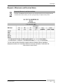
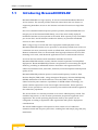
Document History
Document History
Topic
This is the document’s first Release
ii
Description
Date Issued
October 2007
SU-A-EZ Manual
Legal Rights
Legal Rights
© Copyright 2007 Alvarion Ltd. All rights reserved.
The material contained herein is proprietary, privileged, and confidential and
owned by Alvarion or its third party licensors. No disclosure thereof shall be made
to third parties without the express written permission of Alvarion Ltd.
Alvarion Ltd. reserves the right to alter the equipment specifications and
descriptions in this publication without prior notice. No part of this publication
shall be deemed to be part of any contract or warranty unless specifically
incorporated by reference into such contract or warranty.
Trade Names
Alvarion®, BreezeCOM®, WALKair®, WALKnet®, BreezeNET®, BreezeACCESS®,
BreezeMANAGE™, BreezeLINK®, BreezeConfig™, BreezeMAX™, AlvariSTAR™,
AlvariCRAFT™, BreezeLITE™, MGW™, eMGW™ and/or other products and/or
services referenced here in are either registered trademarks, trademarks or
service marks of Alvarion Ltd.
All other names are or may be the trademarks of their respective owners.
Statement of Conditions
The information contained in this manual is subject to change without notice.
Alvarion Ltd. shall not be liable for errors contained herein or for incidental or
consequential damages in connection with the furnishing, performance, or use of
this manual or equipment supplied with it.
Warranties and Disclaimers
All Alvarion Ltd. ("Alvarion") products purchased from Alvarion or through any of
Alvarion's authorized resellers are subject to the following warranty and product
liability terms and conditions.
Exclusive Warranty
(a) Alvarion warrants that the Product hardware it supplies and the tangible
media on which any software is installed, under normal use and conditions, will
be free from significant defects in materials and workmanship for a period of
fourteen (14) months from the date of shipment of a given Product to Purchaser
(the "Warranty Period"). Alvarion will, at its sole option and as Purchaser's sole
remedy, repair or replace any defective Product in accordance with Alvarion'
standard R&R procedure.
(b) With respect to the Firmware, Alvarion warrants the correct functionality
according to the attached documentation, for a period of fourteen (14) month from
SU-A-EZ Manual
iii
Legal Rights
invoice date (the "Warranty Period")". During the Warranty Period, Alvarion may
release to its Customers firmware updates, which include additional performance
improvements and/or bug fixes, upon availability (the "Warranty"). Bug fixes,
temporary patches and/or workarounds may be supplied as Firmware updates.
Additional hardware, if required, to install or use Firmware updates must be
purchased by the Customer. Alvarion will be obligated to support solely the two (2)
most recent Software major releases.
ALVARION SHALL NOT BE LIABLE UNDER THIS WARRANTY IF ITS TESTING
AND EXAMINATION DISCLOSE THAT THE ALLEGED DEFECT IN THE PRODUCT
DOES NOT EXIST OR WAS CAUSED BY PURCHASER'S OR ANY THIRD
PERSON'S MISUSE, NEGLIGENCE, IMPROPER INSTALLATION OR IMPROPER
TESTING, UNAUTHORIZED ATTEMPTS TO REPAIR, OR ANY OTHER CAUSE
BEYOND THE RANGE OF THE INTENDED USE, OR BY ACCIDENT, FIRE,
LIGHTNING OR OTHER HAZARD.
Disclaimer
(a) The Software is sold on an "AS IS" basis. Alvarion, its affiliates or its licensors
MAKE NO WARRANTIES, WHATSOEVER, WHETHER EXPRESS OR IMPLIED,
WITH RESPECT TO THE SOFTWARE AND THE ACCOMPANYING
DOCUMENTATION. ALVARION SPECIFICALLY DISCLAIMS ALL IMPLIED
WARRANTIES OF MERCHANTABILITY AND FITNESS FOR A PARTICULAR
PURPOSE AND NON-INFRINGEMENT WITH RESPECT TO THE SOFTWARE.
UNITS OF PRODUCT (INCLUDING ALL THE SOFTWARE) DELIVERED TO
PURCHASER HEREUNDER ARE NOT FAULT-TOLERANT AND ARE NOT
DESIGNED, MANUFACTURED OR INTENDED FOR USE OR RESALE IN
APPLICATIONS WHERE THE FAILURE, MALFUNCTION OR INACCURACY OF
PRODUCTS CARRIES A RISK OF DEATH OR BODILY INJURY OR SEVERE
PHYSICAL OR ENVIRONMENTAL DAMAGE ("HIGH RISK ACTIVITIES"). HIGH
RISK ACTIVITIES MAY INCLUDE, BUT ARE NOT LIMITED TO, USE AS PART OF
ON-LINE CONTROL SYSTEMS IN HAZARDOUS ENVIRONMENTS REQUIRING
FAIL-SAFE PERFORMANCE, SUCH AS IN THE OPERATION OF NUCLEAR
FACILITIES, AIRCRAFT NAVIGATION OR COMMUNICATION SYSTEMS, AIR
TRAFFIC CONTROL, LIFE SUPPORT MACHINES, WEAPONS SYSTEMS OR
OTHER APPLICATIONS REPRESENTING A SIMILAR DEGREE OF POTENTIAL
HAZARD. ALVARION SPECIFICALLY DISCLAIMS ANY EXPRESS OR IMPLIED
WARRANTY OF FITNESS FOR HIGH RISK ACTIVITIES.
(b) PURCHASER'S SOLE REMEDY FOR BREACH OF THE EXPRESS
WARRANTIES ABOVE SHALL BE REPLACEMENT OR REFUND OF THE
PURCHASE PRICE AS SPECIFIED ABOVE, AT ALVARION'S OPTION. TO THE
FULLEST EXTENT ALLOWED BY LAW, THE WARRANTIES AND REMEDIES SET
FORTH IN THIS AGREEMENT ARE EXCLUSIVE AND IN LIEU OF ALL OTHER
iv
SU-A-EZ Manual
Legal Rights
WARRANTIES OR CONDITIONS, EXPRESS OR IMPLIED, EITHER IN FACT OR BY
OPERATION OF LAW, STATUTORY OR OTHERWISE, INCLUDING BUT NOT
LIMITED TO WARRANTIES, TERMS OR CONDITIONS OF MERCHANTABILITY,
FITNESS FOR A PARTICULAR PURPOSE, SATISFACTORY QUALITY,
CORRESPONDENCE WITH DESCRIPTION, NON-INFRINGEMENT, AND
ACCURACY OF INFORMATION GENERATED. ALL OF WHICH ARE EXPRESSLY
DISCLAIMED. ALVARION' WARRANTIES HEREIN RUN ONLY TO PURCHASER,
AND ARE NOT EXTENDED TO ANY THIRD PARTIES. ALVARION NEITHER
ASSUMES NOR AUTHORIZES ANY OTHER PERSON TO ASSUME FOR IT ANY
OTHER LIABILITY IN CONNECTION WITH THE SALE, INSTALLATION,
MAINTENANCE OR USE OF ITS PRODUCTS.
Limitation of Liability
(a) ALVARION SHALL NOT BE LIABLE TO THE PURCHASER OR TO ANY THIRD
PARTY, FOR ANY LOSS OF PROFITS, LOSS OF USE, INTERRUPTION OF
BUSINESS OR FOR ANY INDIRECT, SPECIAL, INCIDENTAL, PUNITIVE OR
CONSEQUENTIAL DAMAGES OF ANY KIND, WHETHER ARISING UNDER
BREACH OF CONTRACT, TORT (INCLUDING NEGLIGENCE), STRICT LIABILITY
OR OTHERWISE AND WHETHER BASED ON THIS AGREEMENT OR
OTHERWISE, EVEN IF ADVISED OF THE POSSIBILITY OF SUCH DAMAGES.
(b) TO THE EXTENT PERMITTED BY APPLICABLE LAW, IN NO EVENT SHALL
THE LIABILITY FOR DAMAGES HEREUNDER OF ALVARION OR ITS EMPLOYEES
OR AGENTS EXCEED THE PURCHASE PRICE PAID FOR THE PRODUCT BY
PURCHASER, NOR SHALL THE AGGREGATE LIABILITY FOR DAMAGES TO ALL
PARTIES REGARDING ANY PRODUCT EXCEED THE PURCHASE PRICE PAID
FOR THAT PRODUCT BY THAT PARTY (EXCEPT IN THE CASE OF A BREACH OF
A PARTY'S CONFIDENTIALITY OBLIGATIONS).
Electronic Emission Notices
This device complies with Part 15 of the FCC rules.
Operation is subject to the following two conditions:
1
This device may not cause harmful interference.
2
This device must accept any interference received, including interference that
may cause undesired operation.
Radio Frequency Interference Statement
The SU-A-EZ Access Unit has been tested and found to comply with the limits for
a class B digital device, pursuant to part 15 of the FCC rules and to EN 301 489-1
rules.These limits are designed to provide reasonable protection against harmful
interference when the equipment is operated in a residential environment
SU-A-EZ Manual
v
Legal Rights
notwithstanding use in commercial, business and industrial environments. This
equipment generates, uses, and can radiate radio frequency energy and, if not
installed and used in accordance with the instruction manual, may cause harmful
interference to radio communications.
FCC Radiation Hazard Warning
To comply with FCC RF exposure requirement, the antenna used for this
equipment must be fixed-mounted on outdoor permanent structures with a
separation distance of at least 20 centimeters (8 inches) from al persons.
R&TTE Compliance Statement
This equipment complies with the appropriate essential requirements of Article 3
of the R&TTE Directive 1999/5/EC.
Caution
To avoid electrical shock, do not perform any servicing unless you are qualified to
do so.
Line Voltage
Before connecting this instrument to the power line, make sure that the voltage of
the power source matches the requirements of the instrument. The unit must be
connected to an earthed (grounded) outlet to comply with international safety
standards.
Radio
The instrument transmits radio energy during normal operation. To avoid possible
harmful exposure to this energy, do not stand or work for extended periods of time
in front of its antenna. The long-term characteristics or the possible physiological
effects of Radio Frequency Electromagnetic fields have not been yet fully
investigated.
Outdoor Unit and Antenna Installation and Grounding
Ensure that outdoor units, antennas and supporting structures are properly
installed to eliminate any physical hazard to either people or property. Make sure
that the installation of the outdoor unit, antenna and cables is performed in
accordance with all relevant national and local building and safety codes. Even
where grounding is not mandatory according to applicable regulation and national
codes, it is highly recommended to ensure that the outdoor unit and the antenna
mast (when using external antenna) are grounded and suitable lightning
protection devices are used so as to provide protection against voltage surges and
static charges. In any event, Alvarion is not liable for any injury, damage or
regulation violations associated with or caused by installation, grounding or
lightning protection.
vi
SU-A-EZ Manual
Legal Rights
Disposal of Electronic and Electrical Waste
Disposal of Electronic and Electrical Waste
Pursuant to the WEEE EU Directive electronic and electrical waste must not be disposed of with
unsorted waste. Please contact your local recycling authority for disposal of this product.
SU-A-EZ Manual
vii
Legal Rights
Important Notice
This user manual is delivered subject to the following conditions and restrictions:
This manual contains proprietary information belonging to Alvarion Ltd. Such
information is supplied solely for the purpose of assisting properly authorized
users of the respective Alvarion products.
No part of its contents may be used for any other purpose, disclosed to any
person or firm or reproduced by any means, electronic and mechanical,
without the express prior written permission of Alvarion Ltd.
The text and graphics are for the purpose of illustration and reference only.
The specifications on which they are based are subject to change without
notice.
The software described in this document is furnished under a license. The
software may be used or copied only in accordance with the terms of that
license.
Information in this document is subject to change without notice.
Corporate and individual names and data used in examples herein are
fictitious unless otherwise noted.
Alvarion Ltd. reserves the right to alter the equipment specifications and
descriptions in this publication without prior notice. No part of this
publication shall be deemed to be part of any contract or warranty unless
specifically incorporated by reference into such contract or warranty.
The information contained herein is merely descriptive in nature, and does not
constitute an offer for the sale of the product described herein.
Any changes or modifications of equipment, including opening of the
equipment not expressly approved by Alvarion Ltd. will void equipment
warranty and any repair thereafter shall be charged for. It could also void the
user's authority to operate the equipment.
Some of the equipment provided by Alvarion and specified in this manual, is
manufactured and warranted by third parties. All such equipment must be
installed and handled in full compliance with the instructions provided by such
manufacturers as attached to this manual or provided thereafter by Alvarion or
viii
SU-A-EZ Manual
Legal Rights
the manufacturers. Non-compliance with such instructions may result in serious
damage and/or bodily harm and/or void the user's authority to operate the
equipment and/or revoke the warranty provided by such manufacturer.
SU-A-EZ Manual
ix
About This Manual
This manual describes the SU-A-EZ Subscriber Unit and details how to install,
operate and manage it.
This manual is intended for technicians responsible for installing, setting and
operating the BreezeACCESS-EZ system, and for system administrators
responsible for managing the system.
This manual contains the following chapters and appendices:
Chapter 1 - Product Description - Describes the SU-A-EZ unit and its
functionality.
Chapter 2 - Installation - Describes how to install the SU-A-EZ and how to
connect to subscriber’s equipment.
Chapter 3 - Initial Configuration - Describes how to initially configure the
SU-A-EZ in order to test basic link operation.
Chapter 4 - Web-managed Configuration- Describes advanced configuration
of the SU-A-EZ using a web browser.
Chapter 5 - Command Line Interface - Describes advanced configuration of
the SU-A-EZ using Telnet.
Appendix A - Troubleshooting
Table of Contents
Chapter 1 - Product Description
1.1
Introducing BreezeACCESS-EZ................................................................................ 2
1.2
The SU-A-EZ ............................................................................................................... 3
1.3
Specifications............................................................................................................. 4
1.3.1
Radio ............................................................................................................. 4
1.3.2
Sensitivity ...................................................................................................... 5
1.3.3
Transmit Power ............................................................................................. 5
1.3.4
Configuration and Management .................................................................... 6
1.3.5
Mechanical .................................................................................................... 6
1.3.6
Electrical........................................................................................................ 6
1.3.7
Environmental .............................................................................................. 7
1.3.8
Standards Compliance .................................................................................. 7
Chapter 2 - Hardware Installation
2.1
Installation Requirements ....................................................................................... 10
2.1.1
Packing List ................................................................................................. 10
2.1.2
Additional Equipment and Tools Required for Installation........................... 11
2.2
Installation Steps ..................................................................................................... 12
2.3
ODU Hardware Description ..................................................................................... 13
2.3.1
Integrated High-Gain Antenna..................................................................... 13
2.3.2
Ethernet Port ............................................................................................... 13
2.3.3
Ethernet Port Cover (Service Box) .............................................................. 13
2.3.4
Grounding Point .......................................................................................... 14
2.3.5
Water Tight Test Point................................................................................. 14
Table of Contents
2.3.6
Pole-Mounting Bracket Attachment Points.................................................. 14
2.3.7
LED Indicators............................................................................................. 14
2.4
Mounting the SU-A-EZ ODU .................................................................................... 16
2.5
Connecting Cables to the Outdoor Unit................................................................. 21
2.5.1
IDU-ODU Cables......................................................................................... 21
2.5.2
Preparing and Connecting the IDU-ODU Cable.......................................... 22
2.5.3
Grounding Wire ........................................................................................... 23
2.6
The Power Injector IDU............................................................................................ 25
2.7
Connecting the Power Injector IDU Cables ........................................................... 26
2.8
Align the Antenna .................................................................................................... 28
Chapter 3 - Initial Configuration
3.1
Introduction .............................................................................................................. 32
3.2
Setting the Regulatory Domain............................................................................... 33
3.3
Configuring Basic Parameters................................................................................ 35
3.3.1
Accessing the Web Management Interface................................................. 35
3.3.2
Basic Parameters ........................................................................................ 36
Chapter 4 - Web-managed Configuration
4.1
Introduction .............................................................................................................. 40
4.1.1
Main Menu................................................................................................... 40
4.2
Management Settings .............................................................................................. 43
4.3
Wireless Settings ..................................................................................................... 45
4.4
Saving Settings ........................................................................................................ 47
4.5
Status Information ................................................................................................... 48
4.6
Site Survey................................................................................................................ 49
4.7
Managing the SU-A-EZ Configuration.................................................................... 49
4.8
Upgrading SU-A-EZ Firmware................................................................................. 50
xii
SU-A-EZ Manual
Table of Contents
Chapter 5 - Command Line Interface
5.1
5.2
5.3
5.4
5.5
5.6
Using the Command Line Interface........................................................................ 54
5.1.1
Accessing the CLI ....................................................................................... 54
5.1.2
Telnet Connection ....................................................................................... 54
Entering Commands ................................................................................................ 56
5.2.1
Minimum Abbreviation................................................................................. 56
5.2.2
Command Completion................................................................................. 56
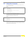
5.2.3
Getting Help on Commands ........................................................................ 57
5.2.4
Partial Keyword Lookup .............................................................................. 58
5.2.5
Using Command History ............................................................................. 58
5.2.6
Command Line Processing ......................................................................... 58
General Commands ................................................................................................. 60
5.3.1
exit............................................................................................................... 60
5.3.2
ping.............................................................................................................. 60
5.3.3
reboot .......................................................................................................... 62
Regulatory Domain Commands.............................................................................. 63
5.4.1
regdomain ................................................................................................... 63
5.4.2
addfreq ........................................................................................................ 64
5.4.3
dynamicfreq................................................................................................. 65
5.4.4
delfreq ......................................................................................................... 66
5.4.5
getfreq ......................................................................................................... 66
Password Commands.............................................................................................. 68
5.5.1
set system password................................................................................... 68
5.5.2
passwd ........................................................................................................ 69
File Commands ........................................................................................................ 70
5.6.1
SU-A-EZ Manual
save-running................................................................................................ 71
xiii
Table of Contents
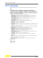
5.7
5.6.2
set config default ......................................................................................... 71
5.6.3
set ClientSta status-update ......................................................................... 71
5.6.4
set tftpftp ftppass ......................................................................................... 72
5.6.5
set tftpftp ftpuser.......................................................................................... 72
5.6.6
set tftpftp ptype............................................................................................ 73
5.6.7
set tftpftp rfile............................................................................................... 73
5.6.8
set tftpftp sip ................................................................................................ 73
5.6.9
set tftpftp start.............................................................................................. 74
5.6.10
get tftpftp ..................................................................................................... 74
5.6.11
get config..................................................................................................... 75
5.6.12
get interface................................................................................................. 76
5.6.13
get system ................................................................................................... 76
5.6.14
get ClientSta................................................................................................ 78
SNMP Commands .................................................................................................... 80
5.7.1
5.8
5.9
xiv
set ClientSta snmp-rocommunity ................................................................ 80
Ethernet Interface Commands ................................................................................ 81
5.8.1
set ClientSta bridge-mip .............................................................................. 81
5.8.2
set ClientSta bridge-static-ip ....................................................................... 81
5.8.3
set ClientSta default-gw .............................................................................. 82
5.8.4
set ClientSta dhcpc ..................................................................................... 82
Wireless Commands................................................................................................ 83
5.9.1
set ClientSta authentication......................................................................... 84
5.9.2
set ClientSta data-encryption-option ........................................................... 84
5.9.3
set ClientSta default-key ............................................................................. 85
5.9.4
set ClientSta distance.................................................................................. 85
5.9.5
set ClientSta key ......................................................................................... 85
SU-A-EZ Manual
Table of Contents
5.9.6
set ClientSta linkrate ................................................................................... 86
5.9.7
set ClientSta mangVLAN............................................................................. 86
5.9.8
set ClientSta modulation ............................................................................. 87
5.9.9
set ClientSta rtsthreshold ............................................................................ 87
5.9.10
set ClientSta txpowerlevel ........................................................................... 88
5.9.11
set ClientSta wireless-essid ........................................................................ 89
5.9.12
get BSSList.................................................................................................. 89
5.9.13
set CStatus clear-cnt yes ............................................................................ 90
5.9.14
get CStatus.................................................................................................. 90
Appendix A - Troubleshooting
SU-A-EZ Manual
xv
1
Chapter 1 - Product Description
In This Chapter:
“Introducing BreezeACCESS-EZ” on page 2
“The SU-A-EZ” on page 3
“Specifications” on page 4
Chapter 1 - Product Description
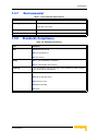
1.1
Introducing BreezeACCESS-EZ
BreezeACCESS-EZ is a high capacity, IP services oriented Broadband Wireless
Access system. The system provides network connections that are always on,
supporting immediate access to the Internet and other IP services at high data
rates.
Part of an extended and field-proven product portfolio, BreezeACCESS-EZ is an
integral part of the BreezeACCESS family, one of the most widely deployed
broadband wireless access systems in the world. With capacity of up to 24 Mbps
per Access Unit, the EZ solution enables the delivery of powerful broadband
services to more subscribers.
With a range of up to 12 Km and lower equipment and deployment costs,
BreezeACCESS-EZ enables service providers to wirelessly extend their services to
customers who were previously unable to afford them, while securing rapid ROI.
Remote residential areas can now benefit from high-speed Internet access, Web
browsing and e-mail, and advanced applications such as multi-media services.
An out-of-the-box solution with immediate available local stock,
BreezeACCESS-EZ enables virtually instant network expansion and simplified
deployment. BreezeACCESS-EZ presents a step forward in overcoming the digital
divide by providing an affordable solution that offers vast opportunities for
enhanced communication, education, business, social development and improved
quality of life.
BreezeACCESS-EZ products operate in unlicensed frequency bands in Time
Division Duplex (TDD) mode, using Orthogonal Frequency Division Multiplexing
(OFDM) modulation with Forward Error Correction (FEC) coding. Using the
enhanced multi-path resistance capabilities of OFDM modem technology, the
system enables operation in near-line-of-sight environments. These qualities
enable service providers to reach a previously inaccessible and broader segment of
the subscriber population.
The Access Units are currently available in several 5 GHz frequency bands. The
available frequencies, as well as other parameters, depend on applicable local
regulations. The actual operating frequencies used by the system can be
configured according to applicable radio regulations and specific deployment
considerations.
The SU-EZ CPEs supports all frequencies from 4.900 to 5.875 GHz with
automatic band and frequency detection, enabling fast and simple plug-and-play
installation.
2
System Description
The SU-A-EZ
1.2
The SU-A-EZ
The Outdoor SU-A-EZ is a wireless client CPE that provides a connection to a
remote AU-EZ Access Unit. The SU-A-EZ operates as an IEEE 802.11a wireless
client, providing a high-speed wireless link between two sites that can be up to 12
Km apart.
The SU-A-EZ Subscriber Unit includes the following components:
Indoor Unit (IDU)
Outdoor Unit (ODU)
The IDU connects to the network through a standard IEEE 802.3 Ethernet
10/100BaseT (RJ 45) interfaces and is powered from the 110/220 VAC mains.
The IDU is connected to the ODU via a Category 5 Ethernet cable. This cable
carries Ethernet traffic between the indoor and the outdoor units, and also
transfers power (54 VDC) from the indoor unit to the outdoor unit.
The ODU outdoor unit contains the processing and radio modules and includes
an integrated high-gain antenna. The ODU is housed in a weatherproof enclosure
for mounting outdoors and includes its own bracket for attaching to a pole, radio
mast, or tower structure.
The SU-EZ CPEs supports all frequencies from 4.900 to 5.875 GHz with
automatic frequency detection, enabling fast and simple plug-and-play
installation.
The SU-A-EZ can be managed through an easy-to-use web interface, CLI, or
SNMP.
SU-A-EZ Manual
3
Chapter 1 - Product Description
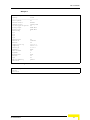
1.3
Specifications
1.3.1
Radio
Table 1-1: Radio Specifications
Item
Description
Radio Type
IEEE 802.11a
Frequency Band
4900-5865 MHz multi-band with automatic frequency detection
Operating Channels
FCC: 5.260, 5.280, 5.300, 5.320, 5.500, 5.520, 5.540, 5.560,
5.580, 5.600, 5.620, 5.640, 5.660, 5.680, 5.700, 5.745, 5.765,
5.785, 5.805, 5.825 GHz
UK: 5.740, 5.750, 5.760, 5.770, 5.780, 5.830, 5.840 GHz
ETSI: 5.500, 5.520, 5.540, 5.560, 5.580, 5.600, 5.620, 5.640,
5.660, 5.680, 5.700 GHz
Japan: 4.920, 4.940, 4.960, 4.980 GHz (not supported currently
by AU-EZ)
Universal: 4.900 ~ 5.865 GHz in 5 MHz steps
Operation Mode
Time Division Duplex (TDD)
Channel Bandwidth
20 MHz
Data Rates
Normal Mode: 6, 9, 12, 18, 24, 36, 48, 54 Mbps per channel
Maximum Throughput
12 Mbps Upload, 12 Mbps download
Radio Technology
Orthogonal Frequency Divisional Multiplexing (OFDM)
Modulation Technique
Binary Phase Shift Keying (BPSK) @ 6 and 9 Mbps
Quadrature Phase Shift Keying (QPSK) @ 12 and 18 Mbps
16-Quadrature Amplitude Modulation (QAM) @ 24 & 36 Mbps
64-QAM @ 48 & 54 Mbps
FEC Coding Rates
1/2 2/3, 3/4
Max Tx Power Levels at Antenna
Port
18 dBm*
TPC (Transmit Power Control)
100%, 50%, 25%, 12.5%, Min (0 dBm).
Antenna
Integrated Flat Panel Antenna, 17dBi, 24°AZ x 18°EL.
*The maximum value can be lower depending on the radio band and modulation used. Check Table 1-3 for
details
4
System Description
Specifications
1.3.2
Sensitivity
Table 1-2: Sensitivity
Data Rate
Sensitivity (dBm)
Modulation/Rate
5.150-5.250 GHz
5.250-5.350 GHz
5.500-5.700 GHz
5.725-5.825 GHz
BPSK (6 Mbps)
-89
-89
-89
-89
BPSK (9 Mbps)
-88
-88
-88
-88
QPSK (12 Mbps)
-86
-86
-86
-87
QPSK (18 Mbps)
-84
-84
-84
-84
16 QAM (24 Mbps)
-81
-81
-81
-80
16 QAM (36 Mbps)
-77
-77
-77
-77
64 QAM (48 Mbps)
-73
-73
-73
-71
64QAM (54 Mbps)
-71
-71
-70
-67
1.3.3
Transmit Power
Table 1-3: Transmit Power
Maximum Output Power (dBm)
Data Rate
5.150-5.250 GHz
5.250-5.350 GHz
5.500-5.700 GHz
5.725-5.825 GHz
6 Mbps
18
18
18
18
9 Mbps
18
18
18
17
12 Mbps
18
18
18
17
8 Mbps
18
18
18
17
24 Mbps
18
18
18
17
36 Mbps
18
18
18
17
48 Mbps
17.5
17
17
16.5
54 Mbps
17.5
17
16.5
15
SU-A-EZ Manual
5
Chapter 1 - Product Description
1.3.4
Configuration and Management
Table 1-4: Configuration and Management
Item
Description
Management options
Web-based (HTTP/HTTPS)
Telnet, SSH (CLI)
SNMP
SNMP agent
V1 / V2c, supports 802.11 MIB, RFC-1213 MIB II and private MIB.
Management access
From Wired LAN, Wireless Link
Management access protection
Access Password
Encryption
WEP 152-bits
Allocation of IP parameters
Configurable or automatic (DHCP client)
Software upgrade
HTTP/FTP/TFTP
Configuration Upload/Download
HTTP
1.3.5
Mechanical
Table 1-5: Mechanical Specifications
Item
Description
Dimensions
195mm (W) X 190mm (H) X 74mm (D)
Weight
1.47Kg
Mounting Bracket Rotation
+/- 360º
1.3.6
Electrical
Table 1-6: Electrical Specifications
Type
Details
AC Power Supply
100-240VAC, 50-60Hz, maximum power consumption 1.5A, meet LPS request
ODU Power supply
55 VDC from the IDU over the indoor-outdoor Ethernet cable
6
System Description
Specifications
1.3.7
Environmental
Table 1-7: Environmental Specifications
Item
Details
Operating Temperature
Outdoor Unit: -40ºC to 60ºC
Indoor Unit: 5ºC to 50ºC
Humidity
Maximum 95%, non-condensing.
Water Proof (ODU)
IP-67
1.3.8
Standards Compliance
Table 1-8: Standards Compliance
Type
Standard
EMC
EN55022 CE Class B
FCC Class B Part 15
VCCI Class B
Safety
UL / CUL (CSA60950-1, UL60950-1)
CE / CB (EN60950-1/IEC 60950-1)
Lightning
The unit withstand at +4KV of Input surge, 1.2usec rise/fall time, 50µsec duration,
every 10 seconds, for all interfaces.
Radio
ETSI 301 893 (11a)
ETSI 301 489 (DC power)
FCC Part 15 (11a)
RSS210 (Canada)
TELEC
SU-A-EZ Manual
7
2
Chapter 2 - Hardware Installation
In This Chapter:
“Installation Requirements” on page 10
“Installation Steps” on page 12
“ODU Hardware Description” on page 13
“Mounting the SU-A-EZ ODU” on page 16
“Connecting Cables to the Outdoor Unit” on page 21
“The Power Injector IDU” on page 25
“Connecting the Power Injector IDU Cables” on page 26
“Align the Antenna” on page 28
Chapter 2 - Hardware Installation
2.1
Installation Requirements
2.1.1
Packing List
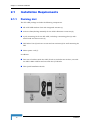
The SU-A-EZ package includes the following components:
SU-A-EZ CPE Outdoor Unit with integrated antenna (1)
A Service Box (Sealing Assembly for the ODU's Ethernet connector) (2)
A pole mounting kit for the SU-A-EZ, including a mounting plate (3) and a
metal band and four screws (4)
IDU Indoor Unit (5) with two screws and two anchors (6) for wall-mounting the
IDU
Mains power cord (7)
In addition:
Two sets of stickers (with the ODU). Each set includes two stickers, one with
the ODU's MAC address and one with the S/N details.
This Quick Installation Guide.
10
Installation
Installation Requirements
2.1.2
Additional Equipment and Tools Required for
Installation
Ethernet cable for connecting to the user’s data equipment (straight-through
for connecting to a switch/hub/router, or cross-over for connecting to a PC).
Indoor-to-outdoor Category 5E Ethernet cable. Use only Category 5E cables
approved by the supplier. The length of the Indoor-to-Outdoor cable should
not exceed 90 meters. The length of the Indoor-to-Outdoor cable, together with
the length of the Ethernet cable connecting the IDU to the data equipment,
should not exceed 100 meters.
Two shielded RJ-45 connectors, and a suitable crimping tool.
Grounding cable with appropriate terminations.
Mains plug adapter or termination plug (if the power plug on the supplied AC
power cord does not fit local power outlets).
Portable PC/Notebook for configuring parameters using either Telnet (CLI) or a
web browser.
Installation tools and materials, including appropriate means (e.g. a pole) for
installing the outdoor unit.
SU-A-EZ Manual
11
Chapter 2 - Hardware Installation
2.2
Installation Steps
CAUTION
ONLY experienced installation professionals who are familiar with local building and safety codes
and, wherever applicable, are licensed by the appropriate government regulatory authorities should
install outdoor units and antennas.
Failure to do so may void the BreezeMAX product warranty and may expose the end user or
Service Provider to legal and financial liabilities. Alvarion and its resellers or distributors are not
liable for injury, damage or regulation violations associated with the installation of Outdoor Units or
antennas.
Hardware installation of the SU-A-EZ involves these steps:
1
Mount the outdoor unit on a pole, mast, or tower using the mounting bracket.
2
Connect the Ethernet cable and a grounding wire to the unit.
3
Connect the power injector IDU to the Ethernet cable, user’s data equipment,
and an AC power source.
4
12
Align the antenna for optimal performance.
Installation
ODU Hardware Description
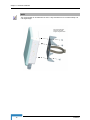
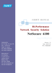
2.3
ODU Hardware Description
Integrated Antenna
SU-A-EZ
Ethernet/P
oE RJ-45 Port
Pole-Mount Bracket
Attachment Points (total 4)
2.3.1
Water-Tight Test Point
(DO NOT REMOVE)
Grounding Point
Screw
Integrated High-Gain Antenna
The SU-A-EZ ODU includes an integrated high-gain (17 dBi) flat-panel antenna
for 5 GHz operation.
2.3.2
Ethernet Port
The SU-A-EZ ODU has one 10BASE-T/100BASE-TX RJ-45 port that connects to
the power injector IDU using an Ethernet cable. The Ethernet port connection
provides power to the SU-A-EZ as well as a data link to the local network via the
IDU.
The unit appears as an Ethernet node and performs a bridging function by moving
packets from the wired LAN to the remote Access Unit (from here on in referred to
as AU.)
2.3.3
Ethernet Port Cover (Service Box)
The SU-A-EZ’s RJ-45 Ethernet port requires the use of a weatherproof cover to
seal the unit.
SU-A-EZ Manual
13
Chapter 2 - Hardware Installation
2.3.4
Grounding Point
Even though the SU-A-EZ includes its own built-in lightning protection, it is
important that the unit is properly connected to ground. A grounding screw is
provided for attaching a ground wire to the unit.
2.3.5
Water Tight Test Point
CAUTION
Do no remove or loosen this screw. Doing so could lead to damage of the unit.
2.3.6
Pole-Mounting Bracket Attachment Points
The SU-A-EZ includes a bracket kit that can be used to mount the unit to a pole,
radio mast, or part of a tower structure.
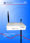
2.3.7
LED Indicators
The SU-A-EZ includes status LED indicators located on the base of the unit, as
indicated in the following figure.
802.11a Wireless
Signal Strength
11a
Power
Power
Link
Ethernet
Link/Activity
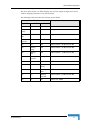
The following table describes the system status LEDs:.
LED
Status
Description
Power
On Green
Indicates that the system is working normally.
On Amber
Indicates a system reset.
On Green
Indicates a valid 10/100 Mbps Ethernet cable link.
Flashing Green
Indicates that the SU-A-EZ is transmitting or receiving data
on a 10/100 Mbps Ethernet LAN. Flashing rate is
proportional to network activity.
Link
14
Installation
ODU Hardware Description
The three pairs of the 11a LEDs display the received signal strength and can be
used for aligning antennas in the wireless link.
The following table describes the wireless status LEDs:
11a LEDs Status
SU-A-EZ Manual
Description
Right Pair
Center Pair
Left Pair
Off
Off
Off
The radio is disabled or unit is still booting up
Blinkingslowly
Off
Off
No signal detected or RSSI is below -88 dBm
Blinkingfast
Off
Off
RSSI is between -88 dBm and -87 dBm
Blinkingvery fast
Off
Off
RSSI is between -86 dBm and -85 dBm
On
Off
Off
RSSI is between -84 dBm and -82 dBm
On
Blinkingslowly
Off
RSSI is between -81 dBm and -80 dBm
On
Blinkingfast
Off
RSSI is between -79 dBm and -78 dBm
On
Blinkingvery fast
Off
RSSI is between -77 dBm and -76dBm
On
On
Off
RSSI is between -75 dBm and -74 dBm
On
On
Blinkingslowly
RSSI is between -73 dBm and -72 dBm
On
On
Blinkingfast
RSSI is between -71 dBm and -70 dBm
On
On
Blinkingvery fast
RSSI is between -69 dBm and -68 dBm
On
On
On
RSSI is over -67dBm
15
Chapter 2 - Hardware Installation
2.4
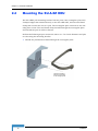
Mounting the SU-A-EZ ODU
The SU-A-EZ’s pole-mounting bracket has two parts: One rectangular plate with
V-shaped edges that attaches directly to the SU-A-EZ ODU, and one steel-band
clamp that secures the unit to a pole. The rectangular plate connects to the unit
using four screws. The steel-band clamp threads through the rectangular plate
and around the pole to which it fastens.
Perform the following steps to mount the unit to a 1.5 to 2 inch diameter steel pole
or tube using the mounting bracket:
1
Thread the provided steel-band through the rectangular plate.
Thread the steel-band
clamp thourgh the slats
on the rectangular plate
16
Installation
Mounting the SU-A-EZ ODU
.
2
Attach the rectangular mounting plate to the SU-A-EZ using the supplied four
screws.
SU-A-EZ Manual
17
Chapter 2 - Hardware Installation
NOTE
The mounting plate can be attached to the unit in a way that allows it to be mounted vertically or at
a 45 degree angle.
Secure the rectangular
plate to the SU-A-EZ
using the supplied screws
18
Installation
Mounting the SU-A-EZ ODU
3
Place the SU-A-EZ with its attached rectangular plate on one side of the pole
and strap the steel-band clamp around the pole. Feed the steel band through
its fastener and secure it tightly.
Strap the steel-band
clamp around the pole
and feed it through the
fastener
NOTE
Be sure to take account of the antenna polarization direction; antennas in a link must be mounted
with the same polarization.
SU-A-EZ Manual
19
Chapter 2 - Hardware Installation
Tighten the steel-band
clamp to secure the
SU-A-EZ to the pole
20
Installation
Connecting Cables to the Outdoor Unit
2.5
Connecting Cables to the Outdoor Unit
WARNING
Do not connect or disconnect cables or otherwise work with the SU-A-EZ during periods of lightning
activity.
2.5.1
IDU-ODU Cables
NOTE
The length of the Indoor-to-Outdoor cable should not exceed 90 meters. The length of the
Indoor-to-Outdoor cable, together with the length of the Ethernet cable connecting the IDU to the
data equipment, should not exceed 100 meters.
Use only Category 5E Ethernet cables from either Alvarion or any of the approved
manufacturers, listed in Table 2-9. Consult with Alvarion's specialists on the
suitability of other cables.
Table 2-9: Approved Category 5E Ethernet Cables
Manufacturer
Part Number
Superior Cables Ltd.
www.superior-cables.com
612098
HES Cabling Systems
H5E-00481
www.hescs.com
Teldor
www.teldor.com
8393204101
Southbay Holdings Limited
11th Fl., 15, Lane 347, Jong Jeng Rd.
Shin Juang City, Taipei County
Taiwan, R.O.C.
Attn: Eva Lin
Tel. 886-2-2832 3339
Fax. 886-2-2206 0081
E-mail: [email protected]
TSM2404A0D
GU-Tech., LLC . - A Member of OVIS GroupTel/Fax :
732 918 8221 Mobile: 718 909 4093
www.OVIS.COM.TW www.GU-TECH.COM
SU-A-EZ Manual
21
Chapter 2 - Hardware Installation
In case of missing information in the manufacturer's WEB site (product
specifications, ordering issues, etc.), it is highly recommended to contact the
manufacturer's sales representative directly.
2.5.2
Preparing and Connecting the IDU-ODU Cable
1
Unscrew the top nut from the Service Box.
2
Route a straight-through Cat. 5 Ethernet cable (8-wire, 24 AWG) through both
the top nut and the body of the Service Box.
3
Insert and crimp the RJ-45 connector. Refer to the cable preparations
instructions described below.
4
Connect the Ethernet cable to the ODU RJ-45 connector.
5
Attach the Service Box to the ODU and tighten the top nut. Make sure that the
external jack of the cable is well inside the Service Box to guarantee good
sealing.
6
Route the cable to the location selected for the indoor equipment. It is
recommended to attach a lightning arrestor to the cable immediately before it
enters the building.
7
Assemble an RJ-45 connector on the indoor end of the ODU cable. Refer to the
pin assignment and color codes in standard cables described below.
IDU-ODU Cable Preparation:
Use a crimp tool for RJ-45 connectors to prepare the wires. Insert them into the
appropriate pins and use the tool to crimp the connector. Make sure to do the
following:
Remove as small a length as possible of the external jacket. Verify that the
external jacket is well inside the sealing cover when connected to the unit, to
ensure good sealing.
Pull back the shield drain wire before inserting the cable into the RJ-45
connector, to ensure a good connection with the connector's shield after
crimping.
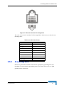
The IDU-ODU cable provides pin-to-pin connection on both ends.
The following figure shows the required wire pair connections.
22
Installation
Connecting Cables to the Outdoor Unit
Figure 2-1: Ethernet Connector Pin Assignments
The color codes used in standard cables supplied by Alvarion are as listed in the
following table:
Table 2-10: Cable Color Codes
2.5.3
Wire color
Pin
Blue
1
Blue/white
2
Orange
3
Orange/white
6
Brown
4
Brown/white
5
Green
7
Green/white
8
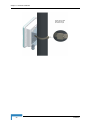
Grounding Wire
Be sure to ground the Outdoor Unit with an appropriate grounding wire (not
included) by connecting the grounding point on the base of the unit to a good
ground (earth) connection.
SU-A-EZ Manual
23
Chapter 2 - Hardware Installation
CAUTION
Be sure that grounding is available and that it meets local and national electrical codes. For
additional lightning protection, use lightning rods, lightning arrestors, or surge suppressors.
RJ-45 Weatherproof Cover
Ground Wire
Ethernet Cable
Grounding Screw
24
Installation
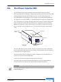
The Power Injector IDU
2.6
The Power Injector IDU
The SU-A-EZ receives power through its network cable connection using
power-over-Ethernet technology. A power injector IDU is included in the SU-A-EZ
package and provides two RJ-45 Ethernet ports, one for connecting to the
SU-A-EZ (Radio), and the other for connecting to a local LAN switch (Ethernet).
The Ethernet port uses an MDI (i.e., internal straight-through) pin configuration.
You can therefore use straight-through twisted-pair cable to connect this port to
most network interconnection devices such as a switch or router that provide
MDI-X ports. However, when connecting the SU-A-EZ to a workstation or other
device that does not have MDI-X ports, you must use a crossover twisted-pair
cable.
AC Power Socket
(Hidden)
LED Indicators
ETH POWER
RADIO
Ethernet from
Local Network
RESET
T
NE
ER
ETH
Reset Button
Ethernet and Power
to SU-A-EZ
The SU-A-EZ does not have a power switch. It is powered on when its Ethernet
port is connected to the power injector module, and the power injector module is
connected to an AC power source.
The Power LED indicates whether AC power is applied. The Link LED does not
function in current release of SU-A-EZ.
In the current release, the Reset button does not function.
The power injector module automatically adjusts to any AC voltage between
100-240 volts at 50 or 60 Hz. No voltage range settings are required.
WARNING
The power injector module is designed for indoor use only. Never mount the power injector outside
with the SU-A-EZ unit.
SU-A-EZ Manual
25
Chapter 2 - Hardware Installation
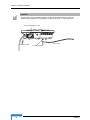
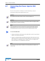
2.7
Connecting the Power Injector IDU
Cables
The unit can be placed on a desktop or a shelf. Alternatively, it may be
wall-mounted using the kit supplied with the unit.
CAUTION
Do not install the power injector outdoors. The unit is for indoor installation only.
CAUTION
Install lightning protection at the power injector end of the Ethernet cable, use a lightning arrestor
immediately before the cable enters the building.
NOTE
The SU-A-EZ’s Ethernet port does not support Power over Ethernet (PoE) based on the IEEE
802.3af standard. Do not try to power the unit by connecting it directly to a network switch that
provides IEEE 802.3af PoE. Always connect the unit to the included power injector module.
To connect the IDU cables:
1
Connect the Ethernet cable from the SU-A-EZ ODU to the RJ-45 port labeled
“Radio” on the power injector IDU.
2
Connect a straight-through unshielded twisted-pair (UTP) cable from a local
LAN switch/router to the RJ-45 port labeled “Ethernet” on the power injector.
If you connect to a workstation, use a crossover cable. Use Category 5E or
better UTP cable for 10/100BASE-TX connections.
NOTE
The RJ-45 port on the power injector is an MDI port. If connecting directly to a computer, use a
crossover cable
26
Installation
Connecting the Power Injector IDU Cables
AC power
RESET
Ethernet cable
to SU-A-EZ
3
Ethernet cable
from LAN switch
RADIO
ET
ERN
ETH
Insert the power cable plug directly into the standard AC receptacle on the
power injector.
4
Plug the other end of the power cable into a grounded, 3-pin socket, AC power
source.
NOTE
For International use, you may need to change the AC line cord. You must use a line cord set that
has been approved for the receptacle type in your country.
5
Check the Power LED on top of the power injector IDU to be sure that power is
being supplied to it.
SU-A-EZ Manual
27
Chapter 2 - Hardware Installation
2.8
Align the Antenna
After the SU-A-EZ unit has been mounted, connected, and its radio is operating,
the antenna must be accurately aligned to ensure optimum performance on the
wireless link. This alignment process is particularly important for long-range
links.
To start the alignment process, you can just point the antenna in the general
direction of the Access Unit’s antenna using binoculars or a compass. For
accurate alignment, you must monitor the signal strength LEDs as the antenna
moves horizontally.
The signal strength LEDs indicate the received radio signal strength for the link.
The more LEDs that turn on, the stronger the signal.
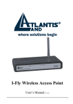
When you move the antenna during alignment, the radio signal from the remote
antenna can be seen to have a strong central main lobe and smaller side lobes.
The object of the alignment process is to set the antenna so that it is receiving the
strongest signal from the central main lobe.
Remote
Antenna
Horizontal Scan
Main Lobe
Maximum
Signal
Strength
Side Lobe
Maximum
Maximum Signal Strength Position
for Horizontal Alignment
To align the antennas in the link, monitor the signal strength LEDs. For details
see “LED Indicators” on page 14. Perform the following procedure:
28
Installation
Align the Antenna
1
Pan the SU-A-EZ antenna horizontally back and forth while checking the
LEDs. Using the pole-mounting bracket with the unit, you must rotate the
mounting bracket around the pole.
2
Find the point where the signal is strongest (refer to “LED Indicators” on
page 14) and secure the bracket in that position.
NOTE
Sometimes there may not be a central lobe peak because vertical alignment is too far off; only two
similar peaks for the side lobes are detected.
SU-A-EZ Manual
29
3
Chapter 3 - Initial Configuration
In This Chapter:
“Introduction” on page 32
“Setting the Regulatory Domain” on page 33
“Configuring Basic Parameters” on page 35
Chapter 3 - Initial Configuration
3.1
Introduction
The SU-A-EZ offers a user-friendly web-based management interface for the
configuration of all the unit’s features. Any PC directly attached to the unit can
access the management interface using a web browser, such as Internet Explorer
(version 6.0 or above).
The initial configuration steps can be made through the web-browser interface
using the default IP address. You can make the initial changes by connecting a PC
directly to the Ethernet port of SU-A-EZ’s power injector IDU before mounting the
unit outdoors in its operating location.
32
Commissioning
Setting the Regulatory Domain
3.2
Setting the Regulatory Domain
Before operating the SU-A-EZ it is important to set the regulatory domain in
which the unit is to operate. Not doing so can result in breaching local laws. The
unit must be installed by a qualified professional.
The SU-A-EZ has a default IP address of 10.0.0.1 and a subnet mask of 255.0.0.0.
If your PC has an IP address (static or assigned by a DHCP server) on the same
subnet then you can connect immediately to the command line interface using
Telnet. Otherwise, you must first change your PC’s IP address to be on the same
subnet as the SU-A-EZ.
To set the regulatory domain you must log into Installer mode from the command
prompt. Specify “installer” as the operating mode and the default password is also
“installer”. For more information on using Telnet and the command prompt see
Chapter 5 - "Command Line Interface."
Example.
ClientSta login: installer
Password:*********
Installer#
Then type “regdomain” followed by the RETURN key. The unit then displays all
possible domain settings. The options are:
•
•
•
•
•
•
FCC - Federal Communications Commission.
ETSI - European Telecommunications Standards Institute.
UK - United Kingdom.
JAPAN - Japan. Not applicable for current release.
Universal - This selects all frequencies in the 802.11a radio bands.
WLG - Not applicable for current release.Access restricted.
WARNING
You must select the regulatory domain that is legally permissable for the country in which you intend
to operate the SU-A-EZ.
This example shows how to display all possible regulatory domains by entering
the syntax “regdomain” followed by the Enter (Return) key. The FCC domain is
then selected by entering the syntax "regdomain FCC".
SU-A-EZ Manual
33
Chapter 3 - Initial Configuration
Example
Installer# regdomain
Usage :
regdomain [FCC | ETSI | UK | JAPAN | Universal | WLG]
Installer# regdomain FCC
Installer#
In order to apply the new selected regulatory domain you need to use the
command "set ClientSta status-update yes" to apply them and "save-running"
command to save all changes. The unit must be reset to fully apply the changes.
34
Commissioning
Configuring Basic Parameters
3.3
Configuring Basic Parameters
Several parameters must be configured to ensure that the unit can function
properly and connect to the Access Unit. Additional parameters may be configured
later, either locally or remotely over the wireless link.
3.3.1
Accessing the Web Management Interface
The SU-A-EZ has a default IP address of 10.0.0.1 and a subnet mask of 255.0.0.0.
If your PC has an IP address (static or assigned by a DHCP server) on the same
subnet then you can connect immediately to the web interface. Otherwise, you
must first change your PC’s IP address to be on the same subnet as the SU-A-EZ.
In the web browser’s address bar, type the default IP address:
http://10.0.0.1.
The web browser displays the SU-A-EZ’s login window.
Figure 3-2: Login Window
Logging In – Type the default user name “admin” and password “private”, then
click OK.
The management interface displays.
SU-A-EZ Manual
35
Chapter 3 - Initial Configuration
Figure 3-3: The SU-A-EZ Management Interface
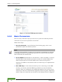
3.3.2
Basic Parameters
There are only a few basic steps you need to set up the SU-A-EZ and provide a
connection to your service provider’s Access Unit.
Follow these steps:
1
Set a New Password – On the Wireless Client Setting page, enter a new
password to replace the default “private”.
NOTE
It is strongly recommended that you configure your own password. If a password is not configured,
the management interface is not protected and anyone that can connect to the SU-A-EZ may be
able to compromise your network security.
2
Set the ESSID (Extended Service Set Identifier) – Enter the SSID, or wireless
network name, of the network you want to connect to. All SU-A-EZs in the
same network must use the same SSID as the remote access point to
associate. The SSID is case sensitive and can consist of up to 31 alphanumeric
characters.
3
Enter WEP Keys – If the wireless network you are connecting to uses WEP
security, you need to enter the WEP key provided to you by the network
operator. Enter “0x” followed by 32 hexadecimal digits (0 to 9 and A to F) for
152 bit keys. Note that Authentication Algorithm, Data encryption, Default key
and all 4 keys (or at least the one selected as the default) must be configured
36
Commissioning
Configuring Basic Parameters
with the same values as those configured in the AP in order to ensure proper
operation.
4
Change the SU-A-EZ IP Address – If the SU-A-EZ’s default IP address is not
compatible with the network you want to connect to, enter an appropriate IP
address and subnet mask as provided by the network operator.
5
SU-A-EZ Manual
Save Your Settings – Click the “Update” button to save all your changes.
37
4
Chapter 4 - Web-managed Configuration
In This Chapter:
“Introduction” on page 40
“Management Settings” on page 43
“Wireless Settings” on page 45
“Saving Settings” on page 47
“Status Information” on page 48
“Site Survey” on page 49
“Managing the SU-A-EZ Configuration” on page 49
“Upgrading SU-A-EZ Firmware” on page 50
Chapter 4 - Web-managed Configuration
4.1
Introduction
The SU-A-EZ’s basic wireless client settings can be configured as described in the
previous chapter, “Initial Configuration.” This chapter describes all the unit’s
settings and features in more detail.
4.1.1
Main Menu
The System Configuration pages include the following options.
Table 4-1: Menu
Menu
Description
Page
Wireless Client Setting
Management
Settings
Configures the access password, IP address, subnet mask, VLAN tag, and SNMP
Read-Only Community setting
43
Password
Configures a new password
43
DHCP Client
Enables / disables the DHCP client
43
Station IP
Address
Configures an IP address for the SU-A-EZ
43
Station Subnet
Mask
Configures a subnet mask for the SU-A-EZ
44
Default Gateway
Configures a gateway for routing traffic to the SU-A-EZ
44
Management
VLAN Tag
Sets the tag for identifying the management VLAN
44
SNMP Read-Only
Community
Sets the SNMP Read-only password
44
Wireless Settings
Configures the SSID, WEP keys, and antenna transmit settings
45
Access Point
ESSID
Configures the Service Set Identifier of the network you want to connect to
45
Authentication
Algorithm
Specifies the authentication method
45
Data Encryption
Option
Enables / disables data encryption
45
Default Key
Configures the key number used for encryption
46
WEP Keys
Configures the WEP key provided by the network you wish to associate with
46
RTS Threshold
Configures the packet size threshold for using RTS/CTS mechanism
46
Transmit Power
Level
Configures the strength of the radio signal from the SU-A-EZ
46
Modulation Type
Specifies the modulation type
46
40
Operation
Introduction
Table 4-1: Menu
Menu
Description
Page
Link Rate
Configures the maximum rate for sending data
46
RF Distance
Configures the maximum distance of the cell
47
Regulatory
Domain
Displays the regulatory domain
47
Information
Status Information
48
Displays wireless client configuration settings for the system
Access Point
ESSID
Displays the Service Set Identifier of the network to which you are connected
48
Access Point
MAC Address
Displays the MAC address of the AP to which the SU-A-EZ is connected
48
Channel
Displays the radio channel the SU-A-EZ is transmitting through
48
Frequency
Displays the frequency at which the SU-A-EZ is transmitting
48
Link Quality
Displays the quality of the link between the SU-A-EZ and the AP
48
RSSI
Displays the Receive Signal Strength Indicator
48
Noise Floor
Displays the ambient noise floor
48
Transmit Power
Level
Displays the overall power level of the SU-A-EZ in a range of minimum to
maximum
48
Rx/Tx
Packets/Bytes
Displays the number of packets/bytes that were sent/received over the wireless
and Ethernet ports
48
Site survey
Displays wireless site survey information
49
Saves the unit’s configuration to a file; restores the configuration from a previously
saved file; resets configuration settings to factory defaults; and resets the unit
49
Maintenance
Configuration
Restore Factory
Default
Restores factory default and reboots the SU-A-EZ
49
Save Current
Configuration
Saves the current configuration to a backup file; you have the option to save the
file in either encrypted or non-encrypted format through the check box
49
Restore
Configuration
Restores a previously saved configuration (in either encrypted or non-encrypted
format) to the SU-A-EZ
50
Reboot Client
Station
Reboots the SU-A-EZ
50
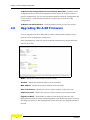
Upgrade
50
Upgrades software from a local file
Model
Displays the SU-A-EZ’s model name
50
Platform
Displays the hardware/software platform number
50
MAC Address
Displays the MAC address of the SU-A-EZ
50
Boot Code
Version
Displays the current version of the boot code
50
SU-A-EZ Manual
41
Chapter 4 - Web-managed Configuration
Table 4-1: Menu
Menu
Description
Page
Firmware Version
Displays the current version of the firmware
50
Upgrade via
HTTP
Allows the user to upgrade firmware by HTTP
50
Upgrade via
TFTP/FTP
Allows the user to upgrade firmware by TFTP/FTP
51
42
Operation
Management Settings
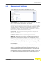
4.2
Management Settings
The SU-A-EZ’s basic client settings are described in this section.
Current Password – The password used to access the web interface. The default
name is “private” (Length: 1-32 characters, case sensitive).
Management access to the web interface on the SU-A-EZ is controlled through a
single user name and password. To protect access to the management interface,
you need to configure an Administrator password as soon as possible. If the
password is not configured, then anyone having access to the SU-A-EZ may be
able to compromise the SU-A-EZ and network security.
New Password – The new password for management access. (Length: 1-32
characters, case sensitive)
Confirm New Password – Enter the password again for verification.
DHCP Client – With DHCP Client enabled, the IP address, subnet mask and
default gateway can be dynamically assigned to the SU-A-EZ by the network
DHCP server. (Default: Disabled). If no DHCP server is found when the unit boots
up or the lease of DHCP assignation expires, then the unit will use the configured
IP address, subnet mask and default gateway until it can find a proper DHCP
server and obtain a valid IP; DHCP server search operation will not stop until the
feature is disabled.
Station IP Address – The IP address of the SU-A-EZ. Valid IP addresses consist of
four decimal numbers, 0 to 255, separated by periods. If the SU-A-EZ’s default IP
address is not compatible with the network you want to connect to, enter an
appropriate IP address and subnet mask as provided by the network operator.
Configuring the SU-A-EZ with an IP address expands your ability to manage the
SU-A-EZ. A number of SU-A-EZ features depend on IP addressing to operate.
SU-A-EZ Manual
43
Chapter 4 - Web-managed Configuration
Station Subnet Mask – The mask that identifies the host IP address bits used for
routing to specific subnets.
NOTE
You can use the web browser interface to access IP addressing only if the SU-A-EZ already has an IP
address that is reachable through your network.
Default Gateway – If a management station exists on another network segment,
then you must enter the IP address for a gateway that can route traffic between
these segments.
Management VLAN Tag – Sets the tag of the management VLAN. (Default: 0,
meaning no VLAN tag)
SNMP Read-Only Community – Sets SNMP Read-only password for SNMP. The
default password is “public” (Length: 1~32 characters, case sensitive).
44
Operation
Wireless Settings
4.3
Wireless Settings
The SU-A-EZ’s wireless settings, ESSID, security, regulatory domain, frequencies
and other radio parameters are described in this section.
Access Point ESSID to Associate – The SSID, or wireless network name, of the
network you want to connect to. All wireless clients and Access Units in the same
network must use the same SSID to associate. The SSID is case sensitive and can
consist of up to 31 alphanumeric characters.
Authentication Algorithm – Sets the SU-A-EZ to communicate with an AU-EZ
configured as an open system, or as a pre-configured system using static shared
keys. (Default: Open System)
Open System: If you don’t set up any other security mechanism on the
SU-A-EZ, the network has no protection. This is the default setting.
Shared Key: Sets the SU-A-EZ to use WEP shared keys. If this option is
selected, you must configure at least one key on the SU-A-EZ and AU-EZ.
Data Encryption Option – Enable or disable the SU-A-EZ to use data encryption
(WEP). If this option is selected when using static WEP keys, you must configure
at least one key on the SU-A-EZ and the AU-EZ. (Default: Disabled)
SU-A-EZ Manual
45
Chapter 4 - Web-managed Configuration
Default Key – Selects the key number to use for encryption. The key indicated by
the default key selection must be configured with the same value in the AP and in
the SU-A-EZ in order for the link to work (Default: Key 1.)
WEP Keys – If the wireless network you are connecting to uses WEP security, you
need to enter the WEP key provided to you by the network operator.
WEP provides a basic level of security, preventing unauthorized access to the
network, and encrypting data transmitted between the SU-A-EZ and AU-EZ. WEP
uses static shared keys (fixed-length hexadecimal) that are manually distributed
to all clients that want to use the network.
Enter “0x” followed by 32 hexadecimal digits (0 to 9 and A to F) for 152 bit keys.
NOTE
All wireless devices must be configured with the same WEP Key values to communicate with an
AU-EZ.
RTS Threshold – Sets the packet size threshold at which a Request to Send (RTS)
signal must be sent to a receiving station prior to the sending station starting
communications. The SU-A-EZ sends RTS frames to a receiving station to
negotiate the sending of a data frame. After receiving an RTS frame, the station
sends a CTS (clear to send) frame to notify the sending station that it can start
sending data.
If the RTS threshold is set to 20, the SU-A-EZ always sends RTS signals. If set to
2347, the SU-A-EZ never sends RTS signals. If set to any other value, and the
packet size equals or exceeds the RTS threshold, the RTS/CTS (Request to Send /
Clear to Send) mechanism will be enabled.
The SU-A-EZs contending for the medium may not be aware of each other. The
RTS/CTS mechanism can solve this “Hidden Node Problem.” (Range: 20-2347
bytes: Default: 60 bytes)
Transmit Power Level – Adjusts the power of the radio signals transmitted from
the SU-A-EZ. The higher the transmission power, the farther the transmission
range. Power selection is not just a trade off between coverage area and maximum
supported clients. You also have to ensure that high-power signals do not
interfere with the operation of other radio devices in the service area. (Options:
Full, Half, Quarter, Eighth, Min (0 dBm); Default: Full)
Modulation Type – Sets the modulation type to limited or fixed. (Default: limited)
Link Rate – The maximum data rate at which the SU-A-EZ transmits unicast
packets on the wireless interface. The maximum transmission distance is affected
46
Operation
Saving Settings
by the data rate. The lower the data rate, the longer the transmission distance.
(Default: 54 Mbps)
RF Distance (Km) – The maximum data transmission distance. The maximum
data rate for a link decreases as the operating range increases. (Default: 1km).
The RF Distance should be set to the distance from the access unit of the furthest
SU in the cell (up-rounded). Since this parameter affects the time the unit waits
for acknowledgement, wromg configuration of its value (too low or too high) may
have a very strong negative effect on performance.
Regulatory Domain – The regulatory domain for the SU-A-EZ is preset for the
country of intended operation and may only be configured through the CLI, (see
“Regulatory Domain Commands” on page 63.) Within the allowed domain for your
country of operation you may limit transmission on certain band frequencies by
deselecting the frequency on the grid and updating your settings. For example,
deselecting 5.2 GHz 60 MHz, disables the 5.260 GHz frequency.
Select All – Selects all available frequencies in the regulatory domain.
Clear All – De-selects all available frequencies in the regulatory domain (at least
one frequency will be retained for security purposes).
4.4
Saving Settings
To save any new settings, click “Update”.
SU-A-EZ Manual
47
Chapter 4 - Web-managed Configuration
4.5
Status Information
The “Review description of this client station” displays basic system configuration
settings and traffic counters for the SU-A-EZ.
Access Point ESSID to Associate – The service set identifier of the network to
which the client wants to associate.
Access Point MAC Address – The physical layer address of the AU-EZ. Specified
in the form of six pairs of hexadecimal digits separated by colons; for example,
00:10:E7:01:02:03.
Channel – Displays the radio channel through which the SU-A-EZ communicates
with the AU-EZ.
Frequency – Displays the frequency at which the SU-A-EZ is transmitting.
Link Quality – Displays the quality of the signal received at the SU-A-EZ.
RSSI – Receive Signal Strength Indicator (RSSI) displays the strength of the
received signal, measured in dBm.
Noise Floor – Indicates the level of interference noise above which the received
signal must be for successful reception, measured in dBm.
Transmit Power Level – Indicates the power of the radio signals transmitted from
the SU-A-EZ.
Rx/Tx Packets/Bytes – The number of received (Rx) and transmitted (Tx) data
packets/bytes since the unit was last reset or since the counters were cleared.
Refresh – Updates the statistics to the most recent data.
Clear – Resets the Rx/Tx counters to a null value.
48
Operation
Site Survey
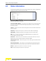
4.6
Site Survey
The Site Survey scans the available frequencies for neighboring wireless devices
(AU-EZ units) that act as APs (that generate beacons).
Scan Access Point – Click this to perform a scan for neighboring wireless devices.
4.7
Managing the SU-A-EZ Configuration
The Maintenance/Configuration page allows you to save and restore the unit’s
configuration settings, restore factory defaults, and to reset the unit.
To Restore Factory Default Configuration – Click the Reset button to set the
configuration settings for the SU-A-EZ to the factory defaults and reboot the
system. Note that all user configured information will be lost. You will have to
re-enter the default user name (admin) and password (private) to re-gain
management access to this device.
To Save the Current Configuration to a Backup File – Click the Backup button
to download the current SU-A-EZ configuration file to the web management
station. Check the Encrypt the configuration file check-box to store the backup
configuration file in an encrypted format.
SU-A-EZ Manual
49
Chapter 4 - Web-managed Configuration
To Restore the Configuration From a Previously Saved File – Sends a saved
configuration file on the web management station to the SU-A-EZ to restore a
specific configuration. You can use the Browse button to find the configuration file
on the local PC. Click the Restore button to replace the current SU-A-EZ
configuration.
To Reboot the Client Station – Click the Reboot button to reset the system.
4.8
Upgrading SU-A-EZ Firmware
You can upgrade new SU-A-EZ firmware (often called system software) from a
local file on the management workstation.
After upgrading new software, the SU-A-EZ will automatically reboot itself and
load the new code.
Model – Shows the model number of the SU-A-EZ.
Platform – Shows the platform number of the hardware.
MAC Address – Shows the physical address of the SU-A-EZ.
Boot Code Version – Shows the current version number of the boot code.
Firmware Version – Shows the current version number of the runtime code.
Upgrade via HTTP – Downloads an software code image file from the web
management station to the SU-A-EZ using HTTP. Use the Browse button to locate
the image file locally on the management station and click the Upgrade button to
proceed.
50
Operation
Upgrading SU-A-EZ Firmware
Upgrade via TFTP/FTP – Downloads an software code image file from the web
management station to the SU-A-EZ using TFTP or FTP.
Protocol Type – Selects either TFTP or FTP.
Server IP Address – Allows you to enter the IP address of the TFTP or FTP
server from which to download code.
FTP Login User – Allows you to enter the FTP user name.
FTP Login Password – Allows you to enter the FTP password.
New Firmware Image – Allows you to enter the name of the chosen update file
stored on the TFTP/FTP server. Select “Upgrade” to start the download
process.
NOTE
Be sure to allow enough time for the firmware download to complete and the unit automatically reboot
itself. Typical download time is 5 minutes when the unit is not handling heavy traffic.
Rebooting the unit before completion of the download may damage the software and cause the unit to
be inoperative..
SU-A-EZ Manual
51
5
Chapter 5 - Command Line Interface
In This Chapter:
“Using the Command Line Interface” on page 54
“Entering Commands” on page 56
“General Commands” on page 60
“Regulatory Domain Commands” on page 63
“Password Commands” on page 68
“File Commands” on page 70
“SNMP Commands” on page 80
“Ethernet Interface Commands” on page 81
“Wireless Commands” on page 83
Chapter 5 - Command Line Interface
5.1
Using the Command Line Interface
5.1.1
Accessing the CLI
When accessing the management interface via a Telnet connection, the SU-A-EZ
(CPE) unit can be managed by entering command keywords and parameters at the
prompt. Using the SU-A-EZ’s command-line interface (CLI) is very similar to
entering commands on a UNIX system.
5.1.2
Telnet Connection
Telnet operates over the IP transport protocol. In this environment, your
management station and any network device you want to manage over the
network must have a valid IP address. Valid IP addresses consist of four numbers,
0 to 255, separated by periods. Each address consists of a network portion and
host portion. For example, if the SU-A-EZ cannot acquire an IP address from a
DHCP server, the default IP address used by the CPE, 10.0.0.1, consists of a
network portion (10) and a host portion (0.0.1).
To access the SU-A-EZ through a Telnet session, you must first use the default IP
address 10.0.0.1.
54
Operation
Using the Command Line Interface
To open a Telnet session:
1
From the remote host, enter the Telnet command and the IP address of the
device you want to access.
2
At the prompt, enter the user name and system password for the command
mode that you wish to enter. There are two command modes: admin mode
and installer mode. Admin mode allows you to configure most settings with the
exception of the regulatory domain. The regulatory domain may be configured
through the installer mode only.
3
The CLI will display the prompt for the mode you enter, for example Installer#
to show that you are using the Installer user account and ClientSta# for
priviledged access mode.
4
Enter the necessary commands to complete your desired tasks.
5
When finished, exit the session with the “exit” command.
After entering the Telnet command, the login screen is displayed:
ClientSta login: installer
Password: *********
Installer#
CAUTION
You can open up to four sessions to the device via Telnet.
SU-A-EZ Manual
55
Chapter 5 - Command Line Interface
5.2
Entering Commands
This section describes how to enter CLI commands.
5.2.1
Minimum Abbreviation
The CLI does not accept incomplete commands. For example, the command
"addfreq" can not be entered as add. In exchange, you can get hints from the CLI
by entering "add" folowed by TAB key. If an entry is ambiguous or incorrect, the
system will not prompt for further input, nor inform you if you have entered
incorrect syntax.
5.2.2
Command Completion
If you terminate input with a Tab key, the CLI will print the remaining characters
of a partial keyword up to the point of ambiguity. In the “configure” example,
typing ex followed by a tab will result in printing the command up to “exit.”
56
Operation
Entering Commands
5.2.3
Getting Help on Commands
You can display a brief description of the help system by pressing the tab key
twice at the command prompt.
Example
ClientSta#
addfreq
delfreq
dynamicfreq
exit
get
getfreq
ping
reboot
save-running
set
Add Frequency
Delete Frequency
Set Exactly Frequency
Logout the system
Get property values of the running configuration
Get Current Frequency
Reboot the system
Save the running configuration
Set property values of the running configuration
The help system may show additional detail by adding a term to query and then
pressing the tab key twice, for example “set” followed by a double tab displays all
parameters associated with this command set only.
Example
Installer# set
CStatus
status class
ClientSta
client station
config
Configuration settings
system
System settings
tftpftp
tftpftp class
Installer# set
Furthermore, adding an additional term displays more help system results, for
example entering “set ClientSta” followed by a double tab displays all parameters
associated with this command subset only.
SU-A-EZ Manual
57
Chapter 5 - Command Line Interface
Example
Installer# set ClientSta
authentication
bridge-mip
bridge-static-ip
data-encryption-option
default-gw
default-key
dhcpc
distance
key-1
key-2
key-3
key-4
linkrate
mangVLAN
modulation
rtsthreshold
snmp-rocommunity
status-update
txpowerlevel
wireless-essid
Installer#
5.2.4
authentication algorithm
bridge ip mask
bridge ip
data encryption option
default gateway
default key
DHCP client
wireless RF distance
wep key string #1
wep key string #2
wep key string #3
wep key string #4
link rate
management VLAN
modulation type
RTS threshold
SNMP read-only community
status of station
TxPower Level
essid
Partial Keyword Lookup
If you terminate a partial keyword with pressing the tab key twice, alternatives
that match the initial letters are provided. (Remember not to leave a space
between the command and tab keys.) For example "s<Tab><Tab>" shows all the
keywords starting with “s.”
Installer# s
save-running
set
Installer# s
5.2.5
Save the running configuration
Set property values of the running configuration
Using Command History
The CLI maintains a history of commands that have been entered. You can scroll
back through the history of commands by pressing the up arrow key. Any
command displayed in the history list can be executed again, or first modified and
then executed.
5.2.6
Command Line Processing
Commands are case sensitive. You can abbreviate commands and parameters as
long as they contain enough letters to differentiate them from any other currently
available commands or parameters. You can use the Tab key to complete partial
58
Operation
Entering Commands
commands. You can also use the following editing keystrokes for command-line
processing:
Table 5-2: Keystroke Commands
Keystroke
Function
Ctrl-A
Shifts cursor to start of command line.
Ctrl-B
Shifts cursor to the left one character.
Ctrl-C
Terminates a task and displays the command prompt.
Ctrl-E
Shifts cursor to end of command line.
Ctrl-F
Shifts cursor to the right one character.
Ctrl-K
Deletes from cursor to the end of the command line.
Ctrl-L
Repeats current command line on a new line.
Ctrl-N
Enters the next command line in the history buffer.
Ctrl-P
Shows the last command.
Ctrl-U
Deletes the entire line.
Ctrl-W
Deletes the last word typed.
Delete key or
backspace key
Erases a mistake when entering a command.
SU-A-EZ Manual
59
Chapter 5 - Command Line Interface
5.3
General Commands
Table 5-3: General Commands
Command
Function
Mode
Page
exit
Logs out of the current session.
Installer;
Admin
60
ping
Sends a ping signal to test for connectivity.
Installer;
Admin
60
reboot
Reboots the unit.
Installer;
Admin
62
5.3.1
exit
The "exit" command allows you to log out of the current session.
Syntax
exit
Default Setting
None
Command Mode
Installer, Admin
Example
This example shows how to logout of the current session:
Installer#exit
ClientSta login:
5.3.2
ping
This command sends ICMP echo request packets to another node on the network.
Syntax
ping <ip_address>
• ip_address - IP address of the host.
Default Setting
None
Command Mode
Installer, Admin
Command Usage
• Use the ping command to see if another site on the network can be reached.
• The following are some results of the ping command:
60
Operation
General Commands
- A normal response occurs in one to ten seconds, depending on network traffic. It
details how many bytes were received, and the time taken from sending the request
to the response.
- If the host does not respond the screen returns a blank and continues sending a ping
request until it is manually stopped by the user with the CTRL+C command. After
typing this command a summary is displayed describing packets transmitted,
packets received and percentage of packet loss.
- If the gateway for the destination is unreachable, or if it found no corresponding entry
in the route table, a “Network is unreachable” message will display.
• Press <Ctrl-C> to stop pinging.
Example 1
Installer# ping 10.0.0.1
PING 10.0.0.1 (10.0.0.1): 56 data bytes
64 bytes from 10.0.0.1: icmp_seq=0 ttl=64
64 bytes from 10.0.0.1: icmp_seq=1 ttl=64
64 bytes from 10.0.0.1: icmp_seq=2 ttl=64
64 bytes from 10.0.0.1: icmp_seq=3 ttl=64
64 bytes from 10.0.0.1: icmp_seq=4 ttl=64
64 bytes from 10.0.0.1: icmp_seq=5 ttl=64
time=0.4
time=0.3
time=0.3
time=0.3
time=0.3
time=0.3
ms
ms
ms
ms
ms
ms
--- 10.0.0.1 ping statistics --6 packets transmitted, 6 packets received, 0% packet loss
round-trip min/avg/max = 0.3/0.3/0.4 ms
Installer#
Example 2
Installer# ping 10.0.0.23
--- 10.0.0.23 ping statistics --78 packets transmitted, 0 packets received, 100% packet loss
Installer#
Example 3
Installer# ping 192.168.2.1
PING 192.168.2.1 (192.168.2.1): 56 data bytes
ping: sendto: Network is unreachable
Installer#
SU-A-EZ Manual
61
Chapter 5 - Command Line Interface
5.3.3
reboot
This command restarts the system.
Syntax
reboot
Default Setting
None
Command Mode
Installer, Admin
Command Usage
When the system is restarted, it will always run the Power-On Self-Test.
Example
This example shows how to reset the system:
Installer#reboot
62
Operation
Regulatory Domain Commands
5.4
Regulatory Domain Commands
Before transmitting wireless data from the unit, you should determine the correct
regulatory domain setting for the country in which you are operating the SU-A-EZ.
Table 5-4: Regulatory Domain Commands
Command
Function
Mode
Page
regdomain
Allows you to select what regional domain to set.
Installer
63
addfreq
Adds one or more individual frequencies or a range of frequencies
within the band allowed by the chosen regulatory domain.
Installer;
Admin
64
dynamicfreq
Configures one or more frequencies or a range of frequencies
within the band allowed by the chosen regulatory domain (old
setting are overwriten).
Installer,
Admin
65
delfreq
Deletes one or more individual frequencies or a range
Installer;
Admin
66
Installer;
Admin
66
of frequencies.
getfreq
5.4.1
Displays the currently used frequencies.
regdomain
This command allows you to set the regulatory domain in which the SU-A-EZ will
be used. After selecting the required domain, the unit must be rebooted for
changes to take effect.
WARNING
You must select the regulatory domain that is legally permissable for the country in which you intend
to operate the SU-A-EZ.
Syntax
regdomain <FCC | ETSI | UK | JAPAN | Universal | WLG>
•
•
•
•
•
FCC - Federal Communications Commission.
ETSI - European Telecommunications Standards Institute.
UK - United Kingdom.
JAPAN - Japan.
Universal - For a testing environment only. Do not select for wireless transmission of
data outside of a test environment. This selects all frequencies in the 802.11a
bandwidth.
• WLG - White Logo: may be customized to a domain other than those stated above.
Access restricted.
SU-A-EZ Manual
63
Chapter 5 - Command Line Interface
Default Setting
Universal
Command Mode
Installer
Example
This example shows how to display all possible regulatory domains by entering
the syntax “regdomain” followed by the RETURN key, followed by selecting the
‘FCC’ domain by entering the syntax “regdomain FCC”.
Installer# regdomain
Usage :
regdomain [FCC | ETSI | UK | JAPAN | Universal | WLG]
Installer# regdomain FCC
Installer# reboot
....
5.4.2
addfreq
This command allows you to add individual frequencies and/or frequency ranges
within the band allowed by the chosen regulatory domain.
Syntax
addfreq <f1 | f2 | f3-f4>
• f1, f2 - Specify the frequencies you wish to add to the regulatory domain, in MHz, i.e.
for the frequency 5.500 GHz type 5500, where the final three digits represent the space
after the decimal point.
• f3-f4 - A frequency range may be entered by separating two frequencies with a “-”, for
example type ‘5500-5560’, to select the range from 5.500GHz to 5.560GHz.
Default Setting
None
Command Mode
Installer, Admin
Example
In this example the command is entered and the following help is displayed by
pressing the ‘enter’ key. The frequency 5.520GHz is then added to the regulatory
domain. Use the getfreq command to display all selected frequencies.
Installer# addfreq
Usage :
addfreq [f1,f2,f3-f4...]
Installer#
Installer# addfreq 5520
Installer#
64
Operation
Regulatory Domain Commands
5.4.3
dynamicfreq
This command allows you to add one or more individual frequencies and a range
of frequencies, allowed by the chosen regulatory domain.
Syntax
dynamicfreq <f1,f2,f3-f4>
• f1,f2,f3-f4 - Specify the individual frequencies and/or frequency ranges that you wish
to add to the already configured scanning frequency list, in MHz, separated by comas
and no spaces. For a frequency range separate the beginning and ending frequencies
with a “-”, i.e. for the frequencies 5.26GHz, 5.54GHz, and the range 5.7~5.785 type
‘5260,5540,5700-5785’, where the final three digits represent the space after the
decimal point.
Default Setting
None
Command Mode
Installer, Admin
Example
In this example the frequencies 5.260GHz, 5.540GHz, and 5.700GHz to 5.785GHz
are added within the band allowed by the chosen regulatory domain FCC. The
getfreq command is then used to display all selected frequencies.
Installer# dynamicfreq 5260,5540,5700-5785
...
Installer# getfreq
...
5260,5540,5700,5745,5765,5785
Installer#
SU-A-EZ Manual
65
Chapter 5 - Command Line Interface
5.4.4
delfreq
This command allows you to delete one or more individual frequencies and/or
ranges of frequencies within a band allowed by the chosen regulatory domain.
Syntax
delfreq <f1 | f2 | f3-f4>
• f1, f2 - Specify the frequencies you wish to remove within a band allowed by the chosen
regulatory domain, in MHz, i.e. for the frequency 5.5GHz type 5500, where the final
three digits represent the space after the decimal point.
• f3-f4 - A frequency range may be entered by separating two frequencies with a “-”, for
example type ‘5500-5560’, to select the range from 5.5GHz to 5.56GHz.
Default Setting
None
Command Mode
Installer, Admin
Example
In this example the frequency 5.500GHz is deleted from the frequency range.
Installer# delfreq 5500
Installer#
5.4.5
getfreq
This command allows you to display all selected frequencies in the chosen
regulatory domain.
Syntax
getfreq
Default Setting
None
Command Mode
Installer, Admin
Example 1
This example shows how to display all selected frequencies in the regulatory
domain ETSI:
Installer# getfreq
5520,5540,5560,5580,5600,5620,5640,5660,5680,5700
Installer#
66
Operation
Regulatory Domain Commands
Example 2
This example shows how to use the addfreq command to add a frequency, the
delfreq command to remove another frequency, and the getfreq command to
display the updated list of frequencies:
Installer# addfreq 5500
Installer# delfreq 5600
Installer# getfreq
5500,5520,5540,5560,5580,5620,5640,5660,5680,5700
Installer#
SU-A-EZ Manual
67
Chapter 5 - Command Line Interface
5.5
Password Commands
After initially logging onto the system, you should set a new password for both
Admin and Installer modes. Remember to record your passwords in a safe place.
Table 5-5: Password Commands
Command
Function
Mode
Page
set system
password
Specifies the password for management access to the Admin
account.
Admin
68
passwd
Specifies the password for management access to the Installer
account.
Installer
69
5.5.1
set system password
This command changes the password for Admin mode.
Syntax
set system password <password>
• password - A string (Range:1~32 printable characters).
Default Setting
“private”
Command Mode
Admin
Example
Admin# set system password a-good-secret
Admin#
68
Operation
Password Commands
5.5.2
passwd
This command changes the password for Installer mode. After entering the
command you will be prompted to enter the new password twice. The password
may be 5~8 characters, using upper and lower case letters and numbers, with no
spaces, nor comas.
Syntax
passwd
Default Setting
“installer”
Command Mode
Installer
Example
Installer# passwd
Changing password for installer
Enter the new password (minimum of 5, maximum of 8 characters)
Please use a combination of upper and lower case letters and numbers.
Enter new password:*********
Re-enter new password:*********
Password changed.
Write Config Area ...Finished!
Installer#
SU-A-EZ Manual
69
Chapter 5 - Command Line Interface
5.6
File Commands
Table 5-6: File Commands
Command
Function
Mode
Page
save-running
Saves the current running configuration.
Installer;
Admin
71
set config default
Reboots the system and restores factory default settings.
Installer,
Admin
71
set ClientSta
status-update
Enables/disables the recording of system status updates in
memory.
Installer,
Admin
71
set tftpftp ftppass
Sets the FTP password.
Installer,
Admin
72
set tftpftp ftpuser
Sets the FTP user name.
Installer,
Admin
72
set tftpftp ptype
Selects the method used for file transfer.
Installer,
Admin
73
set tftpftp rfile
Sets the name of the file for upgrade.
Installer,
Admin
73
set tftpftp sip
Sets the IP address of the FTP or TFTP server.
Installer,
Admin
73
set tftpftp start
Starts the file upgrade process.
Installer,
Admin
74
get tftpftp
Displays detailed information about FTP or TFTP settings.
Installer,
Admin
74
get config
Displays detailed configuration information for the system.
Installer,
Admin
75
get interface
Displays interface information.
Installer,
Admin
76
get system
Displays the SU-A-EZ’s hardware and software versions.
Installer,
Admin
76
get ClientSta
Displays detailed system information about the SU-A-EZ.
Installer,
Admin
78
70
Operation
File Commands
5.6.1
save-running
This command allows you to save the running configuration to flash memory, so
that after a reboot the current configuration will be restored.
Syntax
save-running
Default Setting
No
Command Mode
Installer, Admin
Installer# save-running
Installer#
5.6.2
set config default
This command restores the factory default settings and restarts the system.
Syntax
set config default <yes | no>
• yes - Resets settings to the factory default and reboots the system.
• no - Takes no action.
Default Setting
no
Command Mode
Installer, Admin
Example
Installer# set config default yes
Installer#
5.6.3
set ClientSta status-update
This command enables/disables the saving of any changes to the running
configuration, in the SDRAM. Disabling this feature will result in all changes to
the running configuration being voided. If enabled, when the user has finished
making changes, the running configuration may then be saved to flash memory
using the “save-running” command.
Syntax
set ClientSta status-update <yes | no>
• yes - Enables recording updates to memory.
• no - No action.
SU-A-EZ Manual
71
Chapter 5 - Command Line Interface
Default Setting
no
Command Mode
Installer, Admin
Example
Installer# set ClientSta status-update yes
Installer#
5.6.4
set tftpftp ftppass
Sets the password for FTP software upgrading.
Syntax
set tftpftp ftppass <password>
• password - Alphanumeric string (Range: up to 36 characters).
Default Setting
Disabled
Command Mode
Installer, Admin
Example
Installer# set tftpftp ftppass unforgetable
Installer#
5.6.5
set tftpftp ftpuser
Sets the user name for FTP software upgrading.
Syntax
set tftpftp ftpuser <username>
• username - Alphanumeric string (Range: up to 36 characters).
Default Setting
Disabled
Command Mode
Installer, Admin
Example
Installer# set tftpftp ftpuser David
Installer#
72
Operation
File Commands
5.6.6
set tftpftp ptype
Selects FTP or TFTP for file transfer.
Syntax
set tftpftp ptype <ftp | tftp>
• ftp - Selects FTP.
• tftp - Selects TFTP.
Default Setting
tftp
Command Mode
Installer, Admin
Example
Installer# set tftpftp ptype ftp
Installer#
5.6.7
set tftpftp rfile
Specifies the name of the code file on the server. The new firmware file name
should not contain slashes (\ or /), the leading letter of the file name should not
be a period (.). (Valid characters: A-Z, a-z, 0-9, “.”, “-”, “_”)
Syntax
set tftpftp rfile <file>
• file - The name of the file for transfer.
Default Setting
upgrade.tar
Command Mode
Installer, Admin
Example
Installer# set tftpftp rfile 1.00.14.tar
Installer#
5.6.8
set tftpftp sip
IP address of FTP or TFTP server.
Syntax
set tftpftp sip <IP address>
• IP address - IP address specified in the form xxx.xxx.xxx.xxx.
SU-A-EZ Manual
73
Chapter 5 - Command Line Interface
Default Setting
0.0.0.0
Command Mode
Installer, Admin
Example
Installer# set tftpftp sip 192.168.0.0
Installer#
5.6.9
set tftpftp start
Commences the FTP or TFTP file transfer process.
Syntax
set tftpftp start <yes | no>
• yes - Commences the file transfer process.
• no - Takes no action.
Default Setting
Disabled
Command Mode
Installer, Admin
Example
Installer# set tftpftp start yes
Installer#
5.6.10 get tftpftp
This command displays detailed TFTP or FTP configuration information.
In addition, instead of listing all display parameters, a specific parameter relative
to the configuration may be specified by adding syntax after the command, i.e. get
tftpftp ptype.
Syntax
get tftpftp <detail | parameter>
• detail - Use to display all parameters for this command.
• parameter - Optional parameter used to narrow the query result (see example below).
Default Setting
None
Command Mode
Installer, Admin
74
Operation
File Commands
Example 1
Installer# get tftpftp detail
Property Value
--------------------ptype
tftp
rfile
upgrade.tar
sip
0.0.0.0
ftpuser
ftppass
start
no
Installer#
Example 2
Installer# get tftpftp ptype
tftp
Installer#
5.6.11 get config
This command displays detailed configuration information for the system.
Syntax
get config
get config <default | startup| version>
• default - Displays if the configuration will reset to the default setting after the next
reboot.
• version - Displays the current configuration version file number.
Default Setting
None
Command Mode
Installer, Admin
Example 1
Installer# get config
Property Value
--------------default
no
version
1.02
Installer#
Example 2
Installer# get config default
no
Installer#
SU-A-EZ Manual
75
Chapter 5 - Command Line Interface
5.6.12 get interface
This command displays the interface information for all connections.
Syntax
get interface <all | br0 | lo>
• all - Use to display all parameters for this command.
• br0 - Displays interface information about the SU-A-EZ.
• lo - Displays loopback interface information.
Default Setting
None
Command Mode
Installer, Admin
Example 1
Installer# get interface all
name type
status mac
ip
mask
--------------------------------------------------------------br0
bridge
up
00:10:E7:02:15:5D 10.0.0.1
255.0.0.0
lo
loopback up
00:00:00:00:00:00 127.0.0.1 255.0.0.0
Installer#
Example 2
Installer# get interface lo
Property Value
--------------------------type
loopback
status
up
mac
00:00:00:00:00:00
ip
127.0.0.1
mask
255.0.0.0
Installer#
5.6.13 get system
This command displays detailed hardware and software information for the
system.
Syntax
get system <detail | model | bversion | version | platform>
•
•
•
•
•
76
detail - Use to display all parameters for this command.
model - The SU-A-EZ model number.
bversion - The boot code version number.
version - The software version number.
platform - The design version for integrating software and hardware.
Operation
File Commands
Default Setting
None
Command Mode
Installer, Admin
Example 1
Installer# get system detail
Property Value
------------------model
SU-A-EZ
bversion 1.00.07
version
1.00.14
platform ar531x
Installer#
Example 2
Installer# get system platform
ar531x
Installer#
SU-A-EZ Manual
77
Chapter 5 - Command Line Interface
5.6.14 get ClientSta
This command allows you to display detailed information about the SU-A-EZ.
Syntax
get ClientSta <detail | status-update | wireless-essid | authentication |
data-encryption-option | wep-key-input | wep-key-type | default-key | key-1 |
key-2 | key-3 | key-4 | rtsthreshold | modulation | linkrate | bridge-static-ip |
bridge-mip | default-gw | regdomain | total-channel | mangVLAN | txpowerlevel |
distance | dhcp | snmp-rocommunity>
•
•
•
•
•
•
•
•
•
•
•
•
•
•
•
•
•
•
•
•
•
•
detail - Use to display all parameters for this command.
status-update - Notifies the user if a system status update has been recorded.
wireless-essid - Displays the service set identifier used to identify wireless traffic.
authentication - Displays the type of authentication used.
data-encryption-option - Notifies the user if data encryption is being used on
transmitting data.
wep-key-input - Displays if WEP security is being used.
wep-key-type - Displays the type of WEP security being used, if any.
default-key - Displays the default WEP key.
key-1~key-4 - Displays the WEP key value.
rtsthreshold - Displays the set packet size threshold after which an RTS packet must
be sent.
modulation - Displays the method at which data is being transferred in relation to the
linkrate, fixed or dynamic (limited).
linkrate - Displays the maximum data rate at which the SU-A-EZ can transmit data.
bridge-static-ip - Displays the IP address of the SU-A-EZ.
bridge-mip - Displays the subnet mask for the Ethernet connection.
default-gw - Displays the default gateway for the Ethernet connection.
regdomain - Displays the chosen regulatory domain.
total-channel - Displays the number of channels of bandwidth enabled within the
chosen regulatory domain.
mangVLAN - Displays the ID of the management VLAN.
txpowerlevel - Displays the transmission power level in relation to maximum
capabilities.
distance - Displays the configured distance between the SU-A-EZ’s antenna and the
AP.
dhcp - Displays if DHCP has been enabled.
snmp-rocommunity - Displays the SNMP read-only community access string.
Default Setting
None
Command Mode
Installer, Admin
78
Operation
File Commands
Example 1
Installer# get ClientSta detail
Property
Value
---------------------------------status-update
no
wireless-essid
ESSID1
authentication
OpenSystem
data-encryption-option no
wep-key-input
NONE WEP
wep-key-type
NONE WEP
default-key
1
key-1
key-2
key-3
key-4
rtsthreshold
60
modulation
limited
linkrate
54
bridge-static-ip
10.0.0.1
bridge-mip
255.0.0.0
default-gw
0.0.0.0
regdomain
ETSI
total-channel
10
mangVLAN
0
txpowerlevel
Full
distance
20
dhcpc
no
snmp-rocommunity
public
Installer#
Example 2
Installer# get ClientSta modulation
limited
Installer#
SU-A-EZ Manual
79
Chapter 5 - Command Line Interface
5.7
SNMP Commands
Table 5-7: SNMP Commands
Command
Function
Mode
Page
set ClientSta snmp
-rocommunity
Defines the SNMP read-only access string.
Installer,
Admin
80
5.7.1
set ClientSta snmp-rocommunity
This command defines the SNMP community access string that has read-only
access. Authorized management stations are only able to retrieve MIB objects.
Syntax
set ClientSta snmp-rocommunity <string>
• string - 1~32 alphanumeric characters.
Default Setting
“public”
Command Mode
Installer, Admin
Example
Installer# set ClientSta snmp-rocommunity monkeys
Installer#
80
Operation
Ethernet Interface Commands
5.8
Ethernet Interface Commands
The commands described in this section configure connection parameters for the
Ethernet port.
Table 5-8: Ethernet Interface Commands
Command
Function
Mode
Page
set ClientSta
bridge-mip
Sets the subnet mask for the unit.
Installer,
Admin
81
set ClientSta
bridge-static-ip
Sets the IP address for the unit.
Installer,
Admin
81
set ClientSta
default-gw
Sets the default gateway for passing traffic to the unit.
Installer,
Admin
82
set ClientSta
dhcpc
Enables/disables DHCP on the unit.
Instaler,
Admin
82
5.8.1
set ClientSta bridge-mip
This command sets the subnet mask for the interface.
Syntax
set ClientSta bridge-mip <subnet mask>
• subnet mask - The mask that identifies the host address bits used for routing to specific
subnets. Specified as four decimal numbers, 0 to 255, separated by periods
Default Setting
255.0.0.0
Command Mode
Installer, Admin
Example
Installer# set ClientSta bridge-mip 255.255.255.0
Installer#
5.8.2
set ClientSta bridge-static-ip
This command sets the IP address for the interface.
Syntax
set ClientSta bridge-static-ip <IP address>
• IP address - The IP address of the unit. Specified as four decimal numbers, 0 to 255,
separated by periods
SU-A-EZ Manual
81
Chapter 5 - Command Line Interface
Default Setting
10.0.0.1
Command Mode
Installer, Admin
Example
Installer# set ClientSta bridge-static-ip 192.168.1.1
Installer#
5.8.3
set ClientSta default-gw
This command sets the IP address of the gateway router between this device and
management stations that exist on other network segments.
Syntax
set ClientSta default-gw <gateway IP address>
• gateway IP address - The IP address of the gateway router. Specified as four decimal
numbers, 0 to 255, separated by periods
Default Setting
0.0.0.0
Command Mode
Installer, Admin
Example
Installer# set ClientSta default-gw 192.168.0.0
Installer#
5.8.4
set ClientSta dhcpc
This command enables the SU-A-EZ to obtain an IP address from a DHCP server.
DHCP is disabled by default. To set a new IP address you must first either enable
DHCP, or enter it manually using the “set ClientSta bridge-static-ip” command.
Syntax
set ClientSta dhcpc <yes | no>
• yes - Enables DHCP.
• no - Disables DHCP.
Default Setting
Disabled
Command Mode
Installer, Admin
Example
Installer# set ClientSta dhcpc yes
Installer#
82
Operation
Wireless Commands
5.9
Wireless Commands
The commands described in this section configure connection parameters for the
wireless interfaces.
Table 5-9: Wireless Commands
Command
Function
Mode
Page
set ClientSta
authentication
Defines the 802.11 authentication type allowed by the SU-A-EZ.
Installer,
Admin
84
set ClientSta
data-encryption-op
tion
Enables/disables data encryption.
Installer,
Admin
84
set ClientSta
default-key
Sets the key number for transmission.
Installer,
Admin
85
set ClientSta
distance
Sets the estimated distance between the farthest SU-A-EZ in the
cell and the serving AP.
Installer,
Admin
85
set ClientSta
key-1~4
Allows the user to set up to 4 152-bit hexadecimal keys.
Installer,
Admin
85
set ClientSta
linkrate
Sets the maximum data rate for transmission of wireless packets.
Installer,
Admin
86
set ClientSta
mangVLAN
Sets the management VLAN ID.
Installer,
Admin
86
set ClientSta
modulation
Sets a fixed or dynamic data transmission rate.
Installer,
Admin
87
set ClientSta
rtsthreshold
Sets the packet size threshold at which an RTS must be sent to the
receiving station prior to the sending station starting
communications.
Installer,
Admin
87
set ClientSta
txpowerlevel
Adjusts the power of the radio signals from the SU-A-EZ.
Installer,
Admin
88
set ClientSta
wireless-essid
Allows the user to specify an SSID for the SU-A-EZ.
Installer,
Admin
89
get BSSList
Shows the wireless APs available in the neighborhood.
Installer;
Admin
89
set CStatus
clear-cnt yes
Sets all Rx/Tx display statistics to a null value.
Installer,
Admin
90
get CStatus
Shows the status for the wireless interface.
Installer,
Admin
90
SU-A-EZ Manual
83
Chapter 5 - Command Line Interface
5.9.1
set ClientSta authentication
This command defines the 802.11 authentication type allowed by the SU-A-EZ.
Syntax
set ClientSta authentication <OpenSystem | SharedKey>
• OpenSystem - Can associate to an AU-EZ without verifying its identity using a shared
key. “Open” authentication means either there is no encryption (if encryption is
disabled) or WEP-only encryption is used (if encryption is enabled).
• SharedKey - Authentication is based on a shared key that has been distributed to all
stations.
Default Setting
OpenSystem
Command Mode
Installer, Admin
Example
Installer# set ClientSta authentication SharedKey
Installer#
5.9.2
set ClientSta data-encryption-option
This command enables or disables the SU-A-EZ to use data encryption (WEP). If
this option is selected when using static WEP keys, you must configure at least
one key on the SU-A-EZ.
Syntax
set ClientSta data-encryption-option <yes | no>
• yes - Enables data encryption.
• no - Disables data encryption.
Default Setting
Disabled
Command Mode
Installer, Admin
Example
Installer# set ClientSta data-encryption-option yes
Installer#
84
Operation
Wireless Commands
5.9.3
set ClientSta default-key
This command selects the key number to use for encryption. The key indicated by
the default key selection must be configured with the same value in the AP and in
the SU-A-EZ in order for the link to work.
Syntax
set ClientSta default-key <1 | 2 | 3 | 4>
• The key may be a number between 1 and 4.
Default Setting
1
Command Mode
Installer, Admin
Example
Installer# set ClientSta default-key 2
Installer#
5.9.4
set ClientSta distance
This command allows the user to configure the estimated distance between the AP
and the farthest SU-A-EZ in the cell.
Syntax
set ClientSta distance <distance>
• distance - The distance between antennas in the range 1~50 km.
Default Setting
1 km
Command Mode
Installer, Admin
Example
Installer# set ClientSta distance 25
Installer#
5.9.5
set ClientSta key
This command defines hexadecimal WEP encryption keys on the SU-A-EZ. Up to
four keys may be entered.
Syntax
set ClientSta <key-1 | key-2 | key-3 | key-4> <hex>
• key-1 ~ key-4 - Selects the key number to use for encryption.
• hex - Enter keys as “0x” followed by 32 hexadecimal digits (0-9 and A-F) for 152 bit keys.
SU-A-EZ Manual
85
Chapter 5 - Command Line Interface
Default Setting
Null
Command Mode
Installer, Admin
Example
Installer# set ClientSta key-1
Installer#
5.9.6
0x12345678901234567890123456789012
set ClientSta linkrate
This command sets the maximum data rate at which the SU-A-EZ transmits
unicast packets on the wireless interface. The maximum transmission distance is
affected by the data rate. The lower the data rate, the longer the transmission
distance.
Syntax
set ClientSta linkrate <linkrate>
• linkrate - May be set to 6, 9, 12, 18, 24, 36, 48 or 54 Mbps.
Default Setting
54 Mbps
Command Mode
Installer, Admin
Example
Installer# set ClientSta linkrate 6
Installer#
5.9.7
set ClientSta mangVLAN
This command configures the management VLAN ID. The management VLAN is
for managing the SU-A-EZ. The data traffic is bridged transparently regardless of
this setting.
Syntax
set ClientSta mangVLAN <VLAN ID>
• VLAN ID - Range 0, or 1~4094. 0 implies that the management VLAN is disabled.
Default Setting
Disabled
86
Operation
Wireless Commands
Command Mode
Installer, Admin
Example
Installer# set ClientSta mangVLAN 4094
Installer#
5.9.8
set ClientSta modulation
This command allows you to set fixed or dynamic (limited) transmission rate. If
the modulation is set to fixed, the data transmission rate will be set by the link
rate. However if the modulation is set to dynamic, the transmission rate may be
less than or equal to, but not greater than the link rate.
Syntax
set ClientSta modulation <fixed | limited>
• fixed - Data transmission will be set by the linkrate.
• limited - Modulation will be dynamic according to requirements, i.e. if the linkrate is
set to 24 Mbps, and the modulation is set to limited, then the data transmission rate
could be 6 Mbps, 9 Mbps, 12 Mbps, 18 Mbps, or 24 Mbps.
Default Setting
Limited
Command Mode
Installer, Admin
Example
Installer# set ClientSta modulation fixed
Installer#
5.9.9
set ClientSta rtsthreshold
This command sets the packet size threshold at which a Request to Send (RTS)
signal must be sent to the receiving station prior to the sending station starting
communications.
Syntax
set ClientSta rtsthreshold <threshold>
• threshold - Threshold packet size for which to send an RTS. (Range: 20-2347 bytes)
Default Setting
60
Command Mode
Installer, Admin
SU-A-EZ Manual
87
Chapter 5 - Command Line Interface
Command Usage
If the threshold is set to 20, the SU-A-EZ always sends RTS signals. If set to 2347, the
SU-A-EZ never sends RTS signals. If set to any other value, and the packet size equals
or exceeds the RTS threshold, the RTS/CTS (Request to Send / Clear to Send)
mechanism will be enabled.
The SU-A-EZ sends RTS frames to a receiving station to negotiate the sending of a data
frame. After receiving an RTS frame, the station sends a CTS frame to notify the
SU-A-EZ that it can start sending data.
SU-A-EZs contending for the wireless medium may not be aware of each other. The
RTS/CTS mechanism can solve this “Hidden Node” problem.
Example
Installer# set ClientSta rtsthreshold 20
Installer#
5.9.10 set ClientSta txpowerlevel
This command adjusts the power of the radio signals transmitted from the
SU-A-EZ. The higher the transmission power, the farther the transmission range.
Power selection is not just a trade off between coverage area and maximum
supported clients. You also have to ensure that high-power signals do not
interfere with the operation of other radio devices in the service area. The “full”
transmission power level corresponds to the maximum power level allowed for the
currently used regdomain setting.
Syntax
set ClientSta txpowerlevel <Full | Half | Quarter | Eighth | Min>
•
•
•
•
•
Full - 100% of maximum transmission power level.
Half - 50% of maximum transmission power level.
Quarter - 25% of maximum transmission power level.
Eighth - 12.5% of maximum transmission power level.
Min - Minimum transmission power level (0 dBm).
Default Setting
Full
Command Mode
Installer, Admin
Example
Installer# set ClientSta txpowerlevel Min
Installer#
88
Operation
Wireless Commands
5.9.11 set ClientSta wireless-essid
This command allows the user to set the name of the wireless network.
Syntax
set ClientSta wireless-essid <SSID string>
• SSID string - 1~31 alphanumeric characters.
Default Setting
ESSID1
Command Mode
Installer, Admin
Example
Installer# set ClientSta wireless-essid Alvarion1
Installer#
5.9.12 get BSSList
This command shows all 802.11a wireless devices that act as AP’s (transmit
beacons) within the proximity of the SU-A-EZ. Note, the SU-A-EZ can only
connect to the AU-EZ.
Syntax
get BSSList
get BSSList <essid | apmac | channel | freq | rssi >
• essid - The service set identifier that is attached to packets sent from neighboring
devices.
• apmac - The physical layer address used to uniquely identify the APs.
• channel - The radio channel through which neighboring devices communicate with the
SU-A-EZ.
• freq - The frequency on which neighboring devices are transmitting (this applies only
for 20MHz bandwidth OFDM signals.)
• rssi - A measure of the signal strength received from neighboring devices.
Default Setting
None
Command Mode
Installer, Admin
Example 1
Installer# get BSSList
essid
apmac
channel freq rssi
----------------------------------------------linkutil 00:10:e7:c4:00:ab 148
5740 -73
linkutil 00:10:e7:e4:0c:6b 166
5830 -58
Installer#
SU-A-EZ Manual
89
Chapter 5 - Command Line Interface
Example 2
Installer# get BSSList apmac
apmac
00:10:e7:24:0d:9a
Installer#
5.9.13 set CStatus clear-cnt yes
This command sets all Rx/Tx statistics to a null value.
Syntax
set CStatus clear-cnt yes
Default Setting
None
Command Mode
Installer, Admin
Example
Installer# set CStatus clear-cnt yes
Installer#
5.9.14 get CStatus
This command displays the status of the wireless interface, as well as some
Ethernet statistics.
Syntax
get CStatus
get CStatus <essid | apmac | channel | freq | linkquality | rssi | noisefloor |
txpower | linkstatus | rxpkt-wlan | rxbyte-wlan | txpkt-wlan | txbyte-wlan |
rxpkt-eth | rxbyte-eth | txpkt-eth | txbyte-eth | iface>
•
•
•
•
•
•
•
•
•
•
•
•
•
•
90
essid - The service set identifier that is attached to packets sent from the SU-A-EZ.
apmac - The physical layer address used to uniquely identify the AP.
channel - The radio channel through which the SU-A-EZ communicates with the AP.
freq - The portion of the 802.11a frequency band the SU-A-EZ is using.
linkquality - A measurement of the quality of the signal received by the SU-A-EZ.
rssi - A measure of the received signal strength indicator for the AP.
noisefloor - A level of interference below which signals to and from the SU-A-EZ cannot
be detected.
txpower - A measure of the transmission signal power.
linkstatus - A measure of activity on the link between the SU-A-EZ and associated AP.
rxpkt-wlan - A measurement of the number of wireless packets received by the
SU-A-EZ.
rxbyte-wlan - A measurement of the number of wireless bytes received by the SU-A-EZ.
txpkt-wlan - A measurement of the number of wireless packets transmitted by the
SU-A-EZ.
txbyte-wlan - A measurement of the number of wireless bytes transmitted by the
SU-A-EZ.
rxpkt-eth - A measurement of the number of packets received by the SU-A-EZ over the
Ethernet port.
Operation
Wireless Commands
• rxbyte-eth - A measurement of the number of bytes received by the SU-A-EZ over the
Ethernet port.
• txpkt-eth - A measurement of the number of packets transmitted by the SU-A-EZ over
the Ethernet port.
• txbyte-eth - A measurement of the number of bytes transmitted by the SU-A-EZ over
the Ethernet port.
• iface - The interface for which all the above data is displayed for.
Default Setting
None
Command Mode
Installer, Admin
Example 1
Installer# get CStatus
Property
Value
-----------------------------essid
ESSID1
apmac
00:00:00:00:00:00
channel
108
freq
5540
linkquality 0
rssi
-256
noisefloor
-256
txpower
Full
linkstatus
0
rxpkt-wlan
0
rxbyte-wlan 0
txpkt-wlan
0
txbyte-wlan 0
rxpkt-eth
1041
rxbyte-eth
105870
txpkt-eth
734
txbyte-eth
209723
iface
wlan0
Installer#
Example 2
Installer# get CStatus noisefloor
-256
Installer#
SU-A-EZ Manual
91
A
Appendix A - Troubleshooting
In This Chapter:
This appendix provides a lists of things to check in case of problems before
contacting local Technical Support.
Appendix A - Troubleshooting
Check the following before you contact local Technical Support.
1
If the unit cannot access the network, check the following:
Be sure the SU-A-EZ is configured with the correct Service Set ID (SSID) for
the network to which it is trying to connect.
If authentication or encryption are enabled, ensure that the SU-A-EZ is
properly configured with the appropriate authentication or encryption
keys.
2
If the SU-A-EZ cannot be configured using the Telnet, a web browser, or SNMP
software:
Be sure that the SU-A-EZ has been configured with a valid IP address,
subnet mask and default gateway.
If VLANs are enabled on the wired network, the VLAN tag on the SU-A-EZ
should be set to the same tag as the management VLAN (default: no tag).
Check that you have a valid network connection to the SU-A-EZ.
If you are connecting to the SU-A-EZ through the wired Ethernet interface,
check the network cabling between the management station and the
SU-A-EZ. If you are connecting to SU-A-EZ from the wireless interface,
ensure that you have a valid connection to the SU-A-EZ.
If you cannot connect using Telnet, you may have exceeded the maximum
number of concurrent Telnet sessions permitted (i.e, four sessions). Try
connecting again at a later time, or reboot the unit.
3
If you forgot or lost the password:
Use the "restore factory defaults" or "restore password" mechanism, then
set the SU-A-EZ to its default configuration by powering off the device and
rebooting. Then use the default user name and password for the mode you
wish to access, admin or installer.
Otherwise, contact technical support.
4
If all other recovery measures fail, and the SU-A-EZ is still not functioning
properly, reset the SU-A-EZ’s hardware using the web interface, command
line, or through a power reset.
94
SU-A-EZ Manual
Glossary
100BASE-TX
IEEE 802.3u specification for 100 Mbps Fast Ethernet over two
pairs of Category 5 or better UTP cable.
10BASE-T
IEEE 802.3 specification for 10 Mbps Ethernet over two pairs
of Category 3 or better UTP cable
Authentication
The process to verify the identity of a client requesting network
access. IEEE 802.11 specifies two forms of authentication:
open system and shared key.
Beacon
A signal periodically transmitted from the SU-A-EZ that is used
to identify the service set, and to maintain contact with
wireless clients.
Customer Premise
Equipment (CPE)
Customer Premise Equipment: Communications equipment
that resides on the customer's premises.
Dynamic Host Control
Dynamic Host Configuration Protocol: Provides a framework for
Protocol (DHCP)
passing configuration information to hosts on a TCP/IP
network. DHCP is based on the Bootstrap Protocol (BOOTP),
adding the capability of automatic allocation of reusable
network addresses and additional configuration options.
Ethernet
A popular local area data communications network, which
accepts transmission from computers and terminals.
Encryption
Data passing between the SU-A-EZ and clients can use
encryption to protect from interception and evesdropping.
Extended Service Set
Extended Service Set: More than one wireless cell can be
(ESS)
configured with the same Service Set Identifier to allow mobile
users can roam between different cells with the Extended
Service Set.
File Transfer Protocol
File Transfer Protocol: A TCP/IP protocol used for file transfer.
(FTP)
Hypertext Transfer
Hypertext Transfer Protocol: HTTP is a standard used to
Protocol (HTTP)
transmit and receive all data over the World Wide Web.
Glossary
IEEE 802.11a
A wireless standard that supports high-speed communications
in the 5 GHz band using Orthogonal Frequency Division
Multiplexing (OFDM). The standard supports data rates of 6,
12, 24, and 54 Mbps.
Infrastructure
An integrated wireless and wired LAN is called an
infrastructure configuration.
Local Area Network (LAN)
Local Area Network: A group of interconnected computer and
support devices.
MAC
Media Access Control: The lower of the two sub-layers of the
data link layer defined by the IEEE. The MAC sub-layer
handles access to shared media, such as whether token
passing or contention will be used.
MAC Address
Standardized data link layer address that is required for every
port or device that connects to a LAN. Other devices in the
network use these addresses to locate specific ports in the
network and to create and update routing tables and data
structures. MAC addresses are 6bytes long and are controlled
by the IEEE.
Orthogonal Frequency
Orthogonal Frequency Division Multiplexing: OFDM allows
Division Multiplexing
multiple users to transmit in an allocated band by dividing the
(OFDM)
bandwidth into many narrow bandwidth carriers.
Open System
A security option for the SU-A-EZ which broadcasts a beacon
signal including the configured SSID. Wireless clients can read
the SSID from the beacon, and automatically reset their SSID
to allow immediate connection to the nearest SU-A-EZ.
Power Over Ethernet (PoE)
Power over Ethernet: A specification for providing both power
and data to low-power network devices using a single Category
5 Ethernet cable. PoE provides greater flexibility in the locating
of Wi²s and network devices, and significantly decreased
installation costs.
RTS Threshold
Transmitters contending for the medium may not be aware of
each other. RTS/CTS mechanism can solve this “Hidden Node
Problem.” If the packet size is smaller than the preset RTS
Threshold size, the RTS/CTS mechanism will NOT be enabled.
Service Set Identifier
An identifier that is attached to packets sent over the wireless
(SSID)
LAN and functions as a password for joining a particular radio
cell; i.e., Basic Service Set (BSS).
96
SU-A-EZ Manual
Glossary
Session Key
Session keys are unique to each client, and are used to
authenticate a client connection, and correlate traffic passing
between a specific client and the AU-EZ.
Shared Key
A shared key can be used to authenticate each client attached
to a wireless network. Shared Key authentication must be used
along with the 802.11 Wireless Equivalent Privacy algorithm.
Simple Network
Simple Network Management Protocol: The application
Management Protocol
protocol in the Internet suite of protocols which offers network
(SNMP)
management services.
Trivial File Transfer
Trivial File Transfer Protocol: A TCP/IP protocol commonly
Protocol (TFTP)
used for software downloads.
Virtual LAN (VLAN)
A Virtual LAN is a collection of network nodes that share the
same collision domain regardless of their physical location or
connection point in the network. A VLAN serves as a logical
workgroup with no physical barriers, and allows users to share
information and resources as though located on the same LAN.
Wired Equivalent Privacy
Wired Equivalent Privacy: WEP is based on the use of security
(WEP)
keys and the popular RC4 encryption algorithm. Wireless
devices without a valid WEP key will be excluded from network
traffic.
Wireless Client (SU-A-EZ)
A wireless client is a computer system that accesses a remote
service on another computer (AP) by means of a wireless
transmission signal.
SU-A-EZ Manual
97
Index
A
F
addfreq
factory defaults
64, 65
Authentication Algorithm
restoring
45
62
file commands 70
C
CLI
firmware
upgrading
54
command line interface See CLI
configuration, initial setup
Confirm New Password
Current Password
31
50
G
gateway address
43
54
60
general commands
43
get
D
89
get BSSList
Data Encryption Option
Default Gateway
Default Key
delfreq
89
get ClientSta 78
get config 75
get CStatus 90
get interface 76
get system 76
get tftpftp 74
getfreq 66
45
44
46
66
DHCP Client
43
downloading software
50
grounding point
E
entering commands
56
command completion
command history
getting help
H
56
High-Gain Antenna
58
command line processing
58
57
minimum abbreviation
14
56
partial keyword lookup 58
ESSID 45
I
initial setup
31
IP address
configuring
43
LED indicators
14
Ethernet
port
Ethernet port cover
exit
60
L
13
13
Link Rate
46
login, web 35
13
Index
set ClientSta data-encryption-option
M
set ClientSta default-gw
management settings
43
Management VLAN Tag 44
set ClientSta default-key
managing the CPE configuration
MDI, RJ-45 pin configuration
82
set ClientSta distance 85
set ClientSta key 85
set ClientSta linkrate 86
25
46
mounting the unit 16
set ClientSta mangVLAN
86
set ClientSta modulation 87
set ClientSta rtsthreshold 87
N
43
set ClientSta snmp-rocommunity
passwd
71
set ClientSta txpowerlevel 88
set ClientSta wireless-essid 89
set config default 71
set system password 68
set tftpftp ftppass 72
set tftpftp ftpuser 72
set tftpftp ptype 73
set tftpftp rfile 73
set tftpftp sip 73
set tftpftp start 74
setting the regulatory domain 33
site survey 49
SNMP commands 80
SNMP Read-Only Community 44
69
password commands
PoE
68
60
26
pole-mounting bracket
14
Power over Ethernet See PoE
R
reboot
62
Reboot Client Station
regdomain
50
63
Regulatory Domain
47
regulatory domain commands
reset
80
set ClientSta status-update
P
ping
82
85
set ClientSta dhcpc
49
Modulation Type
New Password
84
63
software
50, 62
resetting the access point
displaying version
restarting the system
downloading
50, 62
50, 62
Restore Configuration from Previously Saved
Restore Factory Default
49
50
specifications
47
RSSI BNC 25
RTS Threshold 46
4
mechanical
radio
49
save-running
71
saving settings 47
6
5
standards compliance
7
transmit power
5
43
Station Subnet Mask 44
status information 48
Station IP Address
set ClientSta Authentication
84
81
set ClientSta bridge-static-ip
100
7
4
sensitivity
Save Configuration to Backup
6
6
environmental
S
set ClientSta bridge-mip
50
configuration and management
electrical
RF Distance
48, 50
81
system software, downloading from server
50
SU-A-EZ Manual
Index
user password
T
Telnet
54
for managenet access
tftp/ftp server IP address
Transmit Power Level
troubleshooting
46
54
73
W
water tight test point
web menu
40
configuring
WEP Keys
U
upgrading software
SU-A-EZ Manual
14
WEP
93
upgrading firmware
43
50
50
46
46
wireless commands
wireless settings
83
45
101