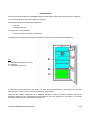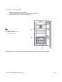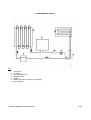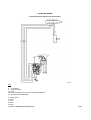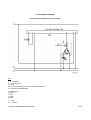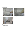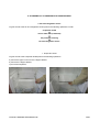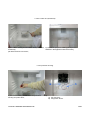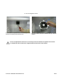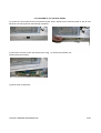
1
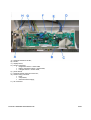
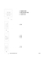
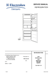
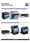
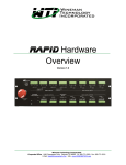
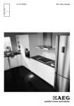
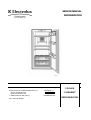
SERVICE MANUAL REFRIGERATION COOLER © ELECTROLUX HOME PRODUCTS S.p.A. Spares Operations Italy Corso Lino Zanussi, 30 I - 33080 PORCIA / PN (ITALY) Fax +39 0434 394096 Publication no. 599 36 16-90 031117 ITZ/SERVICE/AA “0 DEGREE” REFRIGERATOR COOLER 0 DEGREE REFRIGERATOR 2/29 CONTENTS 1. INTRODUCTION ..................................................................................................................................................5 2. MAIN PARTS OF THE APPLIANCE ...................................................................................................................8 a. b. Front view...................................................................................................................................................8 Back view ...................................................................................................................................................9 3. REFRIGERATION CIRCUIT ............................................................................................................................. 11 4. ELECTRIC WIRING .......................................................................................................................................... 12 5. FUNCTIONAL DIAGRAM ................................................................................................................................. 13 6. OPERATION ..................................................................................................................................................... 14 a. Cold requirement only from 0 degree compartment ...................................................................................... 14 b. Cold request from the refrigerator compartment and 0 degree compartment ............................................... 14 c. Cold request from the refrigerator compartment............................................................................................ 14 d. Defrosting activation of the evaporator battery. ............................................................................................. 15 e. Acoustic alarm................................................................................................................................................ 15 7. ACCESSIBILITY TO 0 DEGREE COMPARTMENT ........................................................................................ 16 a. Battery evaporator and evaporator sensor .................................................................................................... 16 b. 0 degree sensor ............................................................................................................................................. 17 8. ACCESSIBILITY TO REFRIGERATOR COMPARTMENT.............................................................................. 18 a. Fan and refrigerator sensor ........................................................................................................................... 18 1. Evaporator shield ....................................................................................................................................... 18 2. Duct or filter duct (if featured)..................................................................................................................... 19 3. Fan protection housing............................................................................................................................... 19 4. Fan and refrigerator sensor........................................................................................................................ 20 9. ACCESSIBILITY TO CONTROL PANEL ......................................................................................................... 21 a. Power board................................................................................................................................................... 24 b. Display board ................................................................................................................................................. 26 c. Electronic board for the fan ............................................................................................................................ 27 10. VARIANT FOR MODELS WITH AIR FILTER ................................................................................................ 28 11. TECHNICAL FEATURES ............................................................................................................................... 29 COOLER 0 DEGREE REFRIGERATOR 3/29 COOLER 0 DEGREE REFRIGERATOR 4/29 1. INTRODUCTION In this manual are described the 0 DEGREE COOLER refrigerators produced in the Florence factory, called ZF. It is a COOLER appliance with PNC: 923524xxx (210 CC). The appliance features the following compartments: 0 degree; refrigerator (cooler); The evaporator circuit consists of: battery evaporator (0 degree compartment). The appliance is controlled by the electronic ERF2000 ( Please refer to Service Manual 599356103). Key: A = refrigerator compartment (cooler); B = separator; C = 0 degree compartment. A separator is placed between the refrigerator and 0 the degree compartments. It is shaped in the front part (near the door) in order to let the air flow inside the two compartments. Unlike the NO FROST refrigerator, the 0 DEGREE refrigerator features a battery evaporator without the defrosting heater and the corresponding thermal switches, since the defrosting of the battery is performed through the operation of the fan with the compressor off. COOLER 0 DEGREE REFRIGERATOR 5/29 3 sensors detect the temperatures: refrigerator sensor (placed near the fan); 0 degree sensor (placed on the cell of the 0 degree compartment); battery evaporator sensor (placed on the battery); Key: A = 0 degree sensor; B = battery evaporator sensor; C = refrigerator sensor; The sensors A, B and C feature the foamed cable inside the cabinet, therefore are not replaceable. COOLER 0 DEGREE REFRIGERATOR 6/29 The cold, produced by the battery evaporator in the 0 degree compartment (behind the evaporator shield E), is diffused firstly into the 0 degree compartment and then into the refrigerator compartment by the fan placed behind the fan protection housing C. The air is sucked by the fan placed in the upper part of the cell, flows through the ducts and reaches the battery evaporator. The cold air exits from the lower part of the battery evaporator, passes next to the two drawers of the 0 degree compartment and goes up to the refrigerator compartment through the space between the separator and the door. AIR FLOW COOLER 0 DEGREE REFRIGERATOR 7/29 2. MAIN PARTS OF THE APPLIANCE a. Front view The main parts of the appliance are listed below: Key: 1. 2. 3. 4. 5. 6. 7. 8. 9. 10. control plate; butter shelf; can shelf ; bottle shelf; 0 degree compartment drawers ( see note @ ); separator; food shelves; air filter ( optional: see note #); rating plate; magnet support. N O T ES: @ The 0 degree compartment drawers feature sliders for the “humidity control“ function: slider closed to maintain humidity; slider open not to maintain humidity. It is important that the drawers are supplied with the covers so as to guarantee the good operation of the “humidity control”. # Depending on the models, in place of the air filter there is a duct which contains a polyester isolating panel. COOLER 0 DEGREE REFRIGERATOR 8/29 b. Back view The main parts of the appliance are listed below: Key: A. B. C. D. E. dehydrator filter; running capacitor (only for some models that feature it); compressor; auxilliary drop tray; drop tray. The auxiliary drop tray is used only on COOLER refrigerators, because the evaporator is bigger than the 4 STARS refrigerators. COOLER 0 DEGREE REFRIGERATOR 9/29 COOLER 0 DEGREE REFRIGERATOR 10/29 3. REFRIGERATION CIRCUIT Key: 1. 2. 3. 4. 5. 6. 7. compressor; condenser; anti-condensation coil; dehydrator filter; capillary; battery evaporator (0 degree compartment); heat exchanger. COOLER 0 DEGREE REFRIGERATOR 11/29 4. ELECTRIC WIRING ( Check the specific diagram for each model! ) Key: 2. 5. 13. 28. 41. compressor; motor protector; lamp; running capacitor (only for the models that feature it); electronic board ERF2000. a. yellow-green; b. brown; c. blue; d. white; e. black; COOLER 0 DEGREE REFRIGERATOR 12/29 5. FUNCTIONAL DIAGRAM ( Check the specific diagram for each model! ) Key: 2. 5. 13. 28. 41. compressor; motor protector; lamp; running capacitor (only for the models that feature it); electronic board ERF2000. a. yellow-green; b. brown; c. blue; d. white; e. black; L N = line; = neutral. COOLER 0 DEGREE REFRIGERATOR 13/29 6. OPERATION The COOLER 0 DEGREE refrigerator operates with different modes depending if the 0 degree and refrigerator compartments require cold. There are 3 possible combinations of normal operation: a. Cold request only from the 0 degree compartment; b. Cold request from refrigerator compartment and 0 degree compartment; c. Cold request only from refrigerator compartment. In addition, there is the condition: d. Defrosting activation of the battery evaporator. a. Cold requirement only from 0 degree compartment If the cold request comes only from the 0 degree compartment: the compressor operates; the fan turns at LOW speed (about 1500 rpm): b. Cold request from the refrigerator compartment and 0 degree compartment If the cold request comes from the two compartments: the compressor operates; the fan turns at HIGH speed (about 1900 rpm): c. Cold request from the refrigerator compartment If the cold request comes from the refrigerator compartment: the compressor does not operate; the fan turns at HIGH speed (about 1900 rpm). COOLER 0 DEGREE REFRIGERATOR 14/29 d. Defrosting activation of the evaporator battery. The frost accumulated on the battery evaporator must be defrosted regularly. The defrosting of the battery evaporator occurs every 3 hours of continuous operation of the compressor. The defrosting heater starts after the compressor cut-out. During the defrosting heater: the compressor does not operate; the fan turns at HIGH speed in continuous mode; the temperature of the refrigerator compartment cools down; the battery evaporator warms up. The defrosting heater terminates when the evaporator sensor detects a temperature of +4 °C. In case of door opening the fan stops. To simulate the door closed use a magnet and put it next to the reed element. e. Acoustic alarm The tone acoustic alarm activates when the door of the appliance remains open for more than 3 minutes. The acoustic alarm is deactivated with the door closure. After 3 minutes the acoustic alarm activates again if the door is open. COOLER 0 DEGREE REFRIGERATOR 15/29 7. ACCESSIBILITY TO 0 DEGREE COMPARTMENT a. Battery evaporator and evaporator sensor To gain access to the battery evaporator and the temperature sensor, perform the following operations: a) remove the upper cover of the 0 degree drawer; b) remove the 0 degree drawer; c) remove the separator; d) remove the 2 fixing screws of the evaporator shield; e) remove the evaporator shield pulling it back and remove the polyester isolating panel; f) A) battery evaporator sensor; B) battery evaporator. COOLER 0 DEGREE REFRIGERATOR 16/29 b. 0 degree sensor To gain access to the 0 degree sensor, perform the following operations: a) remove the upper cover of the 0 degree drawer; b) remove the 0 degree drawer; c) insert a screwdriver with a cutting blade and remove the protection grid of 0 degree sensor; COOLER 0 DEGREE REFRIGERATOR d) A) 0 degree sensor; 17/29 8. ACCESSIBILITY TO REFRIGERATOR COMPARTMENT a. Fan and refrigerator sensor To gain access to the fan and refrigerator sensor perform the following operations in order: evaporator shield ↓ duct or filter duct (if featured) ↓ fan protection housing ↓ fan and refrigerator sensor 1. Evaporator shield To gain access to the evaporator shield perform the following operations: a) remove the upper cover from the 0 degree drawer; b) remove the 0 degree drawer; c) remove the separator; d) remove the 2 fixing screws of the evaporator shield; COOLER 0 DEGREE REFRIGERATOR e) remove the evaporator shield pulling it back; 18/29 2. Duct or filter duct (if featured) a) remove the 2 fixing screws of the duct (or filter duct if featured); pull down the duct to remove it; b) remove the polyester isolating panel (it is not featured in the appliances with the air filter); 3. Fan protection housing a) remove the 2 fixing screws of the fan protection housing and pull it down; COOLER 0 DEGREE REFRIGERATOR b) A) fan connector; B) refrigerator sensor. 19/29 4. Fan and refrigerator sensor a) remove the refrigerator sensor from the support and remove the 3 fixing screws from the fan; b) the fan cables must pass inside the slit (A) in the fan support; In case of replacement of the fan it is necessary to be sure that the fan operates with suction. To simulate the door closed use a magnet and put it next to the reed element. COOLER 0 DEGREE REFRIGERATOR 20/29 9. ACCESSIBILITY TO CONTROL PANEL To access the control panel and its components (power board, display board, electronic board for the fan and electrical connectors) perform the following operations: a) remove the 2 screw covers and remove the 2 fixing screws of the control panel; b) remove the protection foil; c) pull back the control panel; COOLER 0 DEGREE REFRIGERATOR 21/29 A) B) C) D) E) F) G) H) electronic board for the fan; buzzer; display board; sensor connectors refrigerator sensor = white cable; battery evaporator sensor = black cable; 0 degree sensor = brown cable; power board; electronic board connector for the fan; electric wiring connector lamp; compressor; electronic board supply; fan connector. COOLER 0 DEGREE REFRIGERATOR 22/29 COOLER 0 DEGREE REFRIGERATOR 23/29 a. Power board - View of the electronic board (side of components): 1. 2. 3. 4. 5. 6. 7. 8. 9. earth contact; free; line; compressor; neutral; neutral; lamp; free; free; 1. electronic board for the fan; 2. neutral. COOLER 0 DEGREE REFRIGERATOR 24/29 1. 2. 3. 4. 5. 6. refrigerator sensor; refrigerator sensor; battery evaporator sensor; battery evaporator sensor; 0 degree sensor; 0 degree sensor; 1. free; 2. free. 1. 2. 3. 4. free; free; free; free; 1. free; 2. free; COOLER 0 DEGREE REFRIGERATOR 25/29 b. Display board Key: SW1 SW2 SW3 SW4 SW5 SW6 DGT1 DL1 DL2 DL3 DL4 = ON/OFF button; = temperature increase button; = temperature decrease button; = COOLMATIC button; = optional component not mounted; = reed element; = display; = LED -; = optional component not mounted; = COOLMATIC LED; = ON/OFF LED. COOLER 0 DEGREE REFRIGERATOR 26/29 c. Electronic board for the fan - View of the electronic board (side of components): Key: 1. 2. 4. 5. line (board supply); neutral (board supply); +Vcc (board supply); GND (board supply). The output voltage +Vcc presents the following values: +15 . . +18 V DC to make the fan turn at LOW speed; +22 . . +26 V DC to make the fan turn at HIGH speed. COOLER 0 DEGREE REFRIGERATOR 27/29 10. VARIANT FOR MODELS WITH AIR FILTER Depending on the models, in place of the central duct there is the filter duct: a) central duct; b) filter duct; c) open the flap door and replace the carbon filter at least once a year; For the models with air filter it is advisable to use a carbon filter. COOLER 0 DEGREE REFRIGERATOR 28/29 11. TECHNICAL FEATURES 1) Fan: Type Voltage [V cc] 18 . . 26 3414 NMR-418 Power [W] 1,8 Speed [rpm] 2300 2) Power board: Software version NFBF4A0N Board version ERF2000P-01.A 3) Display board: Eeprom F00F4 Board version ERF2000D-06.A See Service Bulletin: 599363646 COOLER 0 DEGREE REFRIGERATOR 29/29