1
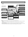
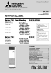
SPLIT-TYPE, HEAT PUMP AIR CONDITIONERS
SPLIT-TYPE, AIR CONDITIONERS
May 2008
No. OC328
REVISED EDITION-B
SERVICE MANUAL
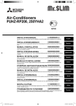
Indoor unit
[Model names]
[Service Ref.]
PCA-RP50GA
PCA-RP50GA2
PCA-RP60GA
PCA-RP71GA
PCA-RP100GA
PCA-RP125GA
PCA-RP140GA
PCA-RP50GA
PCA-RP50GA2
PCA-RP60GA
PCA-RP71GA
PCA-RP100GA
PCA-RP125GA
PCA-RP140GA
PCA-RP50GA#1
PCA-RP50GA2#1
PCA-RP60GA#1
PCA-RP71GA#1
PCA-RP100GA#1
PCA-RP125GA#1
PCA-RP140GA#1
PCH-P60GAH
PCH-P71GAH
PCH-P100GAH
PCH-P125GAH
PCH-P140GAH
• Please void OC328
REVISED EDITION-A
NOTE:
• This manual describes only
service data of the indoor
units.
• RoHS compliant products
have <G> mark on the
spec name plate.
• For servicing of RoHS compliant products, refer to the
RoHS Parts List.
PCH-P50GAH
PCH-P60GAH
PCH-P71GAH
PCH-P100GAH
PCH-P125GAH
PCH-P140GAH
PCH-P50GAH
Revision :
• PCA-RP50~140GA(2)#1
are added in REVISED
EDITION-B.
• RoHS PARTS LIST added.
• Some descriptions have
been modified.
CONTENTS
INDOOR UNIT
TEMP.
ON/OFF
REMOTE CONTROLLER
Model name
indication
1. TECHNICAL CHANGES......................................2
2. REFERENCE MANUAL...............................................2
3. SAFETY PRECAUTION................................... 3
4. PART NAMES AND FUNCTIONS....................7
5. SPECIFICATIONS............................................ 9
6. NOISE CRITERION CURVES........................ 13
7. OUTLINES AND DIMENSIONS..................... 15
8. WIRING DIAGRAM.................................................19
9. REFRIGERANT SYSTEM DIAGRAM.................... 20
10. TROUBLESHOOTING................................... 21
11. SPECIAL FUNCTION..................................... 33
12. DISASSEMBLY PROCEDURE.......................36
13. PARTS LIST....................................................41
14. RoHS PARTS LIST.........................................50
1
TECHNICAL CHANGES
PCA-RP50GA(2)
PCA-RP60GA
PCA-RP71GA
PCA-RP100GA
PCA-RP125GA
PCA-RP140GA
PCA-RP50GA(2)#1
PCA-RP60GA#1
PCA-RP71GA#1
PCA-RP100GA#1
PCA-RP125GA#1
PCA-RP140GA#1
INDOOR CONTROLLER BOARD(I.B.) has been changed.
2
REFERENCE MANUAL
2-1. OUTDOOR UNIT’S SERVICE MANUAL
Service Ref.
Service Manual No.
MXZ-8A140VA / VA1/ VA2 / VA3
SUZ-KA50/60/71VA(1).TH
SUZ-KA50/60/71VA(1).TH-A
PUHZ-RP35/50/60/71/100/125/140VHA(1)
PUHZ-RP100/125/140YHA
PUHZ-RP71/100/125/140VHA(1)-A
PUHZ-RP200/250YHA(1)(2)
PUHZ-RP200/250YHA(1)-A
PU(H)-P • VGAA.UK
PU(H)-P • YGAA.UK
PUHZ-P100/125/140VHA.UK
PUHZ-RP35/50/60/71/100/125/140VHA2(1)
PUHZ-RP100/125/140YHA2(1)
PUHZ-RP35/50/60/71/100VHA3
PUHZ-RP100YHA3
PU(H)-P71/100VHA(1).UK
PU(H)-P100/125/140YHA(1).UK
PUHZ-P100/125/140VHA2(1).UK
PUHZ-RP71/100/125/140VHA2-A
PUHZ-RP100/125/140YHA2-A
PUHZ-BP100/125/140VHA-A
PUHZ-BP200/250YHA-A
PUHZ-P200/250YHA2
PUHZ-HRP71/100VHA
PUHZ-HRP100/125YHA
PUHZ-RP200/250YHA2
OC316
OC322
OC323
OC334
OC337
OC338
OC339
OC336
OC359
OC374
OC379
OCH415 / OCB415
OCH422 / OCB422
OCH423 / OCB423
OCH424 / OCB424
OCH425 / OCB425
OCH428 / OCB428
2-2. TECHNICAL DATA BOOK
Series (Outdoor unit)
Manual No.
PUHZ-RP • HA(-A)
PU(H)-P • GAA.UK
SUZ-KA • VA
PUHZ-RP • HA2
PUHZ-P • HA
PU(H)-P • HA
PUHZ-P • VHA2, PUHZ-P • YHA
PUHZ-RP • HA2-A
PUHZ-BP • HA
PUHZ-HRP • HA
OCS01
OCS02
OCS03
OCS05
OCS06
OCS07
OCS08
OCS09
OCS10
OCS11
2
3
SAFETY PRECAUTION
3-1. ALWAYS OBSERVE FOR SAFETY
Before obtaining access to terminal, all supply
circuits must be disconnected.
3-2. CAUTIONS RELATED TO NEW REFRIGERANT
Cautions for units utilising refrigerant R407C
Do not use the existing refrigerant piping.
Use liquid refrigerant to charge the system.
The old refrigerant and lubricant in the existing piping
contains a large amount of chlorine which may cause the
lubricant deterioration of the new unit.
If gas refrigerant is used to seal the system, the composition
of the refrigerant in the cylinder will change and performance
may drop.
Use “low residual oil piping”
Do not use a refrigerant other than R407C.
If there is a large amount of residual oil (hydraulic oil, etc.)
inside the piping and joints, deterioration of the lubricant
will result.
If another refrigerant (R22, etc.) is used, the chlorine in the
refrigerant may cause the lubricant deterioration.
Use a vacuum pump with a reverse flow check valve.
Store the piping to be used during installation
indoors with keep both ends sealed until just
before brazing.
(Store elbows and other joints in a plastic bag.)
The vacuum pump oil may flow back into the refrigerant
cycle and cause the lubricant deterioration.
Ventilate the room if refrigerant leaks during
operation. If refrigerant comes into contact with
a flame, poisonous gases will be released.
If dust, dirt, or water enters the refrigerant cycle,
deterioration of the oil and compressor trouble may result.
Use ESTER , ETHER or HAB as the lubricant to
coat flares and flange connection parts.
If large amount of mineral oil enter, that can cause
deterioration of refrigerant oil etc.
3
[1] Cautions for service
·After recovering the all refrigerant in the unit, proceed to working.
·Do not release refrigerant in the air.
·After completing the repair service, recharge the cycle with the specified amount of
liquid refrigerant.
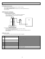
[2] Refrigerant recharging
(1) Refrigerant recharging process
1Direct charging from the cylinder.
·R407C cylinder are available on the market has a syphon pipe.
·Leave the syphon pipe cylinder standing and recharge it.
(By liquid refrigerant)
Unit
Gravimeter
(2) Recharge in refrigerant leakage case
·After recovering the all refrigerant in the unit, proceed to working.
·Do not release the refrigerant in the air.
·After completing the repair service, recharge the cycle with the specified amount of
liquid refrigerant.
[3] Service tools
Use the below service tools as exclusive tools for R407C refrigerant.
No.
1
Tool name
Specifications
Gauge manifold
·Only for R407C.
·Use the existing fitting SPECIFICATIONS. (UNF7/16)
·Use high-tension side pressure of 3.43MPa·G or over.
2
Charge hose
3
Electronic scale
·Only for R407C.
·Use pressure performance of 5.10MPa·G or over.
—
4
Gas leak detector
·Use the detector for R134a or R407C.
5
Adapter for reverse flow check.
·Attach on vacuum pump.
6
Refrigerant charge base.
7
Refrigerant cylinder.
—
·For R407C
·Top of cylinder (Brown)
·Cylinder with syphon
8
—
Refrigerant recovery equipment.
4
CAUTIONS RELATED TO NEW REFRIGERANT
Cautions for units utilising refrigerant R410A
Use new refrigerant pipes.
Do not use refrigerant other than R410A.
In case of using the existing pipes for R22, be careful with
the followings.
· For RP60/71VHA3 and RP100/125/140, be sure to
perform replacement operation before test run.
· Change flare nut to the one provided with this product.
Use a newly flared pipe.
· Avoid using thin pipes.
If other refrigerant (R22 etc.) is used, chlorine in refrigerant can cause deterioration of refrigerant oil etc.
Use a vacuum pump with a reverse flow check
valve.
Vacuum pump oil may flow back into refrigerant cycle and
that can cause deterioration of refrigerant oil etc.
Make sure that the inside and outside of refrigerant piping is clean and it has no contamination
such as sulfur hazardous for use, oxides, dirt,
shaving particles, etc.
In addition, use pipes with specified thickness.
Use the following tools specifically designed for
use with R410A refrigerant.
The following tools are necessary to use R410A refrigerant.
Contamination inside refrigerant piping can cause deterioration of refrigerant oil etc.
Gauge manifold
Charge hose
Gas leak detector
Torque wrench
Tools for R410A
Flare tool
Size adjustment gauge
Vacuum pump adaptor
Electronic refrigerant
charging scale
Store the piping to be used during installation
indoors and keep both ends of the piping sealed
until just before brazing. (Leave elbow joints, etc.
in their packaging.)
Keep the tools with care.
If dirt, dust or moisture enter into refrigerant cycle, that can
cause deterioration of refrigerant oil or malfunction of compressor.
If dirt, dust or moisture enter into refrigerant cycle, that can
cause deterioration of refrigerant oil or malfunction of compressor.
Use ester oil, ether oil or alkylbenzene oil (small
amount) as the refrigerant oil applied to flares
and flange connections.
Do not use a charging cylinder.
If large amount of mineral oil enter, that can cause deterioration of refrigerant oil etc.
If a charging cylinder is used, the composition of refrigerant will change and the efficiency will be lowered.
Ventilate the room if refrigerant leaks during
operation. If refrigerant comes into contact with
a flame, poisonous gases will be released.
Charge refrigerant from liquid phase of gas
cylinder.
If the refrigerant is charged from gas phase, composition
change may occur in refrigerant and the efficiency will be
lowered.
[1] Cautions for service
(1) Perform service after collecting the refrigerant left in unit completely.
(2) Do not release refrigerant in the air.
(3) After completing service, charge the cycle with specified amount of refrigerant.
(4) When performing service, install a filter drier simultaneously.
Be sure to use a filter drier for new refrigerant.
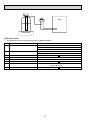
[2] Additional refrigerant charge
When charging directly from cylinder
· Check that cylinder for R410A on the market is syphon type.
· Charging should be performed with the cylinder of syphon stood vertically. (Refrigerant is charged from liquid phase.)
5
Unit
Gravimeter
[3] Service tools
Use the below service tools as exclusive tools for R410A refrigerant.
No.
1
Specifications
Gauge manifold
·Only for R410A
·Use the existing fitting specifications. (UNF1/2)
·Use high-tension side pressure of 5.3MPa·G or over.
2
Charge hose
3
Electronic scale
4
Gas leak detector
·Use the detector for R134a, R407C or R410A.
·Attach on vacuum pump.
·Only for R410A
·Use pressure performance of 5.09MPa·G or over.
5
Adaptor for reverse flow check
6
Refrigerant charge base
7
Refrigerant cylinder
·Only for R410A
Top of cylinder (Pink)
Cylinder with syphon
8
Refrigerant recovery equipment
6
4
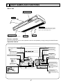
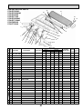
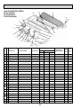
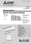
PART NAMES AND FUNCTIONS
Indoor Unit
Left/right guide vanes
Change the direction of airflow
from the horizontal blower.
Air outlet
Long-life filter
Removes dust and foreign matter from air coming in
through the grille (Recommended cleaning interval :
Approx, every 2,500 operating hours)
Up/down guide vanes
Change the direction of airflow from the
vertical blower.
Air intake
Intake grille
Remote controller
Once the controls are set, the same operation mode can be repeated by simply pressing the ON/OFF button.
Operation buttons
ON/OFF button
Set Temperature buttons
Down
Fan Speed button
Up
Timer Menu button
(Monitor/Set button)
Filter
button
(<Enter> button)
Mode button (Return button)
TEMP.
ON/OFF
Set Time buttons
Check button (Clear button)
Back
Ahead
Test Run button
MENU
BACK
MONITOR/SET
ON/OFF
FILTER
DAY
CHECK TEST
Airflow Up/Down button
Timer On/Off button
(Set Day button)
PAR-21MAA
CLOCK
OPERATION
CLEAR
Louver button
(
Operation button)
To preceding operation
number.
Opening the
door.
Ventilation button
Operation button)
(
To next operation number.
7
Display
“Sensor” indication
Displayed when the remote controller
sensor is used.
Day-of-Week
For purposes of this explanation,
all parts of the display are shown
as lit. During actual operation, only
the relevant items will be lit.
Shows the current day of the week.
Time/Timer Display
“Locked” indicator
Shows the current time, unless the simple or Auto Off
timer is set.
If the simple or Auto Off timer is set, shows the time
remaining.
Indicates that remote controller buttons have been locked.
Identifies the current operation
“Clean The Filter” indicator
Shows the operating mode, etc.
* Multilanguage display is supported.
Comes on when it is time to clean the
filter.
TIME SUN MON TUE WED THU FRI SAT
TIMER
Hr
ON
AFTER
FUNCTION
FILTER
°F°C
“Centrally Controlled” indicator
Indicates that operation of the remote controller has been prohibited by a master controller.
Timer indicators
AFTER OFF
ERROR CODE
°F°C
The indicator comes on if the corresponding timer is set.
WEEKLY
SIMPLE
AUTO OFF
ONLY1Hr.
Fan Speed indicator
Shows the selected fan speed.
“Timer Is Off” indicator
Indicates that the timer is off.
Temperature Setting
Shows the target temperature.
Up/Down Air Direction indicator
Room Temperature display
Shows the room temperature.
The indicator
shows the direction of the outcoming airflow.
Louver display
“One Hour Only” indicator
Indicates the action of the swing
louver. Does not appear if the
louver is stationary.
Displayed if the airflow is set to
weak and downward during COOL
or DRY mode. (Operation varies
according to model.)
The indicator goes off after one
hour, at which time the airflow direction also changes.
Ventilation indicator
Appears when the unit is running in
Ventilation mode.
(Power On indicator)
Indicates that the power is on.
Caution
Only the Power on indicator lights when the unit is stopped and power supplied to the unit.
If you press a button for a feature that is not installed at the indoor unit, the remote controller will display the “Not Available”
message.
If you are using the remote controller to drive multiple indoor units, this message will appear only if he feature is not
present at the parent unit.
When power is turned ON for the first time, it is normal that “PLEASE WAIT” is displayed on the room temperature indication
(For max. 2minutes). Please wait until this “PLEASE WAIT” indication disappear then start the operation.
8
INDOOR UNIT
Service Ref.
Mode
Power supply(phase, cycle, voltage)
Input
kW
Running current
A
Starting current
A
External finish
Heat exchanger
Fan
Fan(drive) x No.
Fan motor output
kW
Airflow(Low-Medium2-Medium1-High) */min(CFM)
External static pressure
Pa(mmAq)
Operation control & Thermostat
Noise level(Low-Medium2-Medium1-High)
dB
Unit drain pipe I.D.
mm(in.)
Dimensions
mm(in.)
W
mm(in.)
D
mm(in.)
H
Weight
kg(lbs)
INDOOR UNIT
Service Ref.
Mode
Power supply(phase, cycle, voltage)
kW
Input
A
Running current
A
Starting current
External finish
Heat exchanger
Fan
Fan(drive) x No.
kW
Fan motor output
Airflow(Low-Medium2-Medium1-High) */min(CFM)
Pa(mmAq)
External static pressure
Operation control & Thermostat
dB
Noise level(Low-Medium2-Medium1-High)
mm(in.)
Unit drain pipe I.D.
mm(in.)
Dimensions
W
mm(in.)
D
mm(in.)
H
kg(lbs)
Weight
INDOOR UNIT
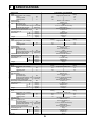
SPECIFICATIONS
INDOOR UNIT
5
PCA-RP50GA, PCA-RP50GA#1
Cooling
Heating
Single phase, 50Hz, 230V
0.09
0.41
1.20
0.09
0.41
1.20
Munsell 0.70Y 8.59/0.97
Plate fin coil
Sirocco fan (direct) x 2
0.054
10-11-12-13(355-390-425-460)
0(direct blow)
Remote controller & built-in
37-38-40-42
26(1)
1,000(39-3/8)
680(26-3/4)
210(8-1/4)
27(60)
PCA-RP50GA2, PCA-RP50GA2#1
Cooling
Heating
Single phase, 50Hz, 230V
0.12
0.12
0.53
0.53
1.27
1.27
Munsell 0.70Y 8.59/0.97
Plate fin coil
Sirocco fan (direct) x 3
0.070
14-15-16-18(495-530-565-635)
0(direct blow)
Remote controller & built-in
37-39-41-43
26(1)
1,310(51-9/16)
680(26-3/4)
210(8-1/4)
34(75)
PCA-RP60GA, PCA-RP60GA#1
Cooling
Heating
Single phase, 50Hz, 230V
0.12
0.53
1.27
0.12
0.53
1.27
Munsell 0.70Y 8.59/0.97
Plate fin coil
Sirocco fan (direct) x 3
0.070
14-15-16-18(495-530-565-635)
0(direct blow)
Remote controller & built-in
37-39-41-43
26(1)
1,310(51-9/16)
680(26-3/4)
210(8-1/4)
34(75)
Service Ref.
Mode
Power supply(phase, cycle, voltage)
Input
kW
Running current
A
Starting current
A
External finish
Heat exchanger
Fan
Fan(drive) x No.
Fan motor output
kW
Airflow(Low-Medium2-Medium1-High) */min(CFM)
External static pressure
Pa(mmAq)
Operation control & Thermostat
Noise level(Low-Medium2-Medium1-High)
dB
Unit drain pipe I.D.
mm(in.)
Dimensions
mm(in.)
W
mm(in.)
D
mm(in.)
H
Weight
kg(lbs)
PCA-RP71GA, PCA-RP71GA#1
Cooling
Heating
Single phase, 50Hz, 230V
0.12
0.53
1.27
0.12
0.53
1.27
Munsell 0.70Y 8.59/0.97
Plate fin coil
Sirocco fan (direct) x 3
0.070
14-15-16-18(495-530-565-635)
0(direct blow)
Remote controller & built-in
37-39-41-43
26(1)
1,310(51-9/16)
680(26-3/4)
210(8-1/4)
34(75)
9
INDOOR UNIT
Service Ref.
Mode
Power supply(phase, cycle, voltage)
kW
Input
A
Running current
A
Starting current
External finish
Heat exchanger
Fan
Fan(drive) x No.
kW
Fan motor output
Airflow(Low-Medium2-Medium1-High) */min(CFM)
Pa(mmAq)
External static pressure
Operation control & Thermostat
dB
Noise level(Low-Medium2-Medium1-High)
mm(in.)
Unit drain pipe I.D.
mm(in.)
Dimensions
W
mm(in.)
D
mm(in.)
H
kg(lbs)
Weight
PCA-RP100GA, PCA-RP100GA#1
Cooling
Heating
Single phase, 50Hz, 230V
0.15
0.15
0.69
0.69
1.48
1.48
Munsell 0.70Y 8.59/0.97
Plate fin coil
Sirocco fan (direct) x 3
0.090
20-21-23-25(705-740-810-885)
0(direct blow)
Remote controller & built-in
40-41-43-45
26(1)
1,310(51-9/16)
680(26-3/4)
270(10-5/8)
37(82)
INDOOR UNIT
Service Ref.
Mode
Power supply(phase, cycle, voltage)
Input
kW
Running current
A
Starting current
A
External finish
Heat exchanger
Fan
Fan(drive) x No.
Fan motor output
kW
Airflow(Low-Medium2-Medium1-High) */min(CFM)
External static pressure
Pa(mmAq)
Operation control & Thermostat
Noise level(Low-Medium2-Medium1-High)
dB
Unit drain pipe I.D.
mm(in.)
Dimensions
mm(in.)
W
mm(in.)
D
mm(in.)
H
Weight
kg(lbs)
PCA-RP125GA, PCA-RP125GA#1
Cooling
Heating
Single phase, 50Hz, 230V
0.22
0.22
1.01
1.01
2.20
2.20
Munsell 0.70Y 8.59/0.97
Plate fin coil
Sirocco fan (direct) x 4
0.150
27-30-32-34(955-1,060-1,130-1,200)
0(direct blow)
Remote controller & built-in
41-43-45-46
26(1)
1,620(63-3/4)
680(26-3/4)
270(10-5/8)
43(95)
INDOOR UNIT
Service Ref.
Mode
Power supply(phase, cycle, voltage)
Input
kW
Running current
A
Starting current
A
External finish
Heat exchanger
Fan
Fan(drive) x No.
Fan motor output
kW
Airflow(Low-Medium2-Medium1-High) */min(CFM)
External static pressure
Pa(mmAq)
Operation control & Thermostat
Noise level(Low-Medium2-Medium1-High)
dB
Unit drain pipe I.D.
mm(in.)
Dimensions
mm(in.)
W
mm(in.)
D
mm(in.)
H
Weight
kg(lbs)
PCA-RP140GA, PCA-RP140GA#1
Cooling
Heating
Single phase, 50Hz, 230V
0.22
0.22
1.01
1.01
2.20
2.20
Munsell 0.70Y 8.59/0.97
Plate fin coil
Sirocco fan (direct) x 4
0.150
27-30-32-34(955-1,060-1,130-1,200)
0(direct blow)
Remote controller & built-in
42-44-46-48
26(1)
1,620(63-3/4)
680(26-3/4)
270(10-5/8)
45(99)
10
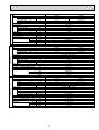
INDOOR UNIT
Service Ref.
Mode
Power supply(phase, cycle, voltage)
Input
+1
kW
Running current
+1
A
Starting current
+1
A
External finish
Heat exchanger
Fan
Fan(drive) x No.
Fan motor output
kW
Airflow(Low-Medium2-Medium1-High) */min(CFM)
External static pressure
Pa(mmAq)
Booster heater
+1
kW
Operation control & Thermostat
Noise level(Low-Medium2-Medium1-High)
dB
Unit drain pipe I.D.
mm(in.)
Dimensions
mm(in.)
W
mm(in.)
D
mm(in.)
H
Weight
kg(lbs)
INDOOR UNIT
Service Ref.
Mode
Power supply(phase, cycle, voltage)
kW
Input
+1
A
Running current
+1
A
Starting current
+1
External finish
Heat exchanger
Fan
Fan(drive) x No.
kW
Fan motor output
Airflow(Low-Medium2-Medium1-High) */min(CFM)
Pa(mmAq)
External static pressure
kW
Booster heater
+1
Operation control & Thermostat
dB
Noise level(Low-Medium2-Medium1-High)
mm(in.)
Unit drain pipe I.D.
mm(in.)
W
Dimensions
mm(in.)
D
mm(in.)
H
kg(lbs)
Weight
PCH-P50GAH
Cooling
Heating
Single phase, 50Hz, 230V
0.09
0.41
1.20
0.09<1.29>
0.41<5.61>
1.20<5.61>
Munsell 0.70Y 8.59/0.97
Plate fin coil
Sirocco fan (direct) x 2
0.054
10-11-12-13(355-390-425-460)
0(direct blow)
<1.29>
Remote controller & built-in
37-38-40-42
26(1)
1,000(39-3/8)
680(26-3/4)
210(8-1/4)
28.5(63)
PCH-P60GAH
Cooling
Heating
Single phase, 50Hz, 230V
0.12
0.53
1.27
0.12<1.93>
0.53<8.39>
1.27<8.39>
Munsell 0.70Y 8.59/0.97
Plate fin coil
Sirocco fan (direct) x 3
0.070
14-15-16-18(495-530-565-635)
0(direct blow)
<1.93>
Remote controller & built-in
37-39-41-43
26(1)
1,310(51-9/16)
680(26-3/4)
210(8-1/4)
36(79)
PCH-P71GAH
Cooling
Heating
Single phase, 50Hz, 230V
0.12
0.53
1.27
0.12<1.93>
0.53<8.39>
1.27<8.39>
Munsell 0.70Y 8.59/0.97
Plate fin coil
Sirocco fan (direct) x 3
0.070
14-15-16-18(495-530-565-635)
0(direct blow)
<1.93>
Remote controller & built-in
37-39-41-43
26(1)
1,310(51-9/16)
680(26-3/4)
210(8-1/4)
36(79)
+1 : < > Shows the only booster heater rating.
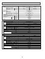
11
INDOOR UNIT
Service Ref.
Mode
Power supply(phase, cycle, voltage)
Input
+1
kW
Running current
+1
A
Starting current
+1
A
External finish
Heat exchanger
Fan
Fan(drive) x No.
Fan motor output
kW
Airflow(Low-Medium2-Medium1-High) */min(CFM)
External static pressure
Pa(mmAq)
Booster heater
+1
kW
Operation control & Thermostat
Noise level(Low-Medium2-Medium1-High)
dB
Unit drain pipe I.D.
mm(in.)
Dimensions
mm(in.)
W
mm(in.)
D
mm(in.)
H
Weight
kg(lbs)
INDOOR UNIT
Service Ref.
Mode
Power supply(phase, cycle, voltage)
Input
+1
kW
Running current
+1
A
Starting current
+1
A
External finish
Heat exchanger
Fan
Fan(drive) x No.
Fan motor output
kW
Airflow(Low-Medium2-Medium1-High) */min(CFM)
External static pressure
Pa(mmAq)
Booster heater
+1
kW
Operation control & Thermostat
Noise level(Low-Medium2-Medium1-High)
dB
Unit drain pipe I.D.
mm(in.)
Dimensions
mm(in.)
W
mm(in.)
D
H
mm(in.)
Weight
kg(lbs)
INDOOR UNIT
Service Ref.
Mode
Power supply(phase, cycle, voltage)
Input
+1
kW
Running current
+1
A
Starting current
+1
A
External finish
Heat exchanger
Fan
Fan(drive) x No.
Fan motor output
kW
Airflow(Low-Medium2-Medium1-High) */min(CFM)
External static pressure
Pa(mmAq)
Booster heater
+1
kW
Operation control & Thermostat
Noise level(Low-Medium2-Medium1-High)
dB
Unit drain pipe I.D.
mm(in.)
Dimensions
mm(in.)
W
mm(in.)
D
mm(in.)
H
Weight
kg(lbs)
PCH-P100GAH
Cooling
Heating
Single phase, 50Hz, 230V
0.15
0.69
1.48
0.15<2.48>
0.69<10.78>
1.48<10.78>
Munsell 0.70Y 8.59/0.97
Plate fin coil
Sirocco fan (direct) x 3
0.090
20-21-23-25(705-740-810-885)
0(direct blow)
<2.48>
Remote controller & built-in
40-41-43-45
26(1)
1,310(51-9/16)
680(26-3/4)
270(10-5/8)
39.5(87)
PCH-P125GAH
Cooling
Heating
Single phase, 50Hz, 230V
0.22
1.01
2.20
0.22<2.76>
1.01<12.00>
2.20<12.00>
Munsell 0.70Y 8.59/0.97
Plate fin coil
Sirocco fan (direct) x 4
0.150
27-30-32-34(955-1,060-1,130-1,200)
0(direct blow)
<2.76>
Remote controller & built-in
41-43-45-46
26(1)
1,620(63-3/4)
680(26-3/4)
270(10-5/8)
46(101)
PCH-P140GAH
Cooling
Heating
Single phase, 50Hz, 230V
0.22
1.01
2.20
0.22<2.76>
1.01<12.00>
2.20<12.00>
Munsell 0.70Y 8.59/0.97
Plate fin coil
Sirocco fan (direct) x 4
0.150
27-30-32-34(955-1,060-1,130-1,200)
0(direct blow)
<2.76>
Remote controller & built-in
42-44-46-48
26(1)
1,620(63-3/4)
680(26-3/4)
270(10-5/8)
48(106)
+1 : < > Shows the only booster heater rating.
12
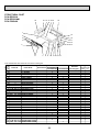
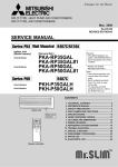
6
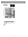
NOISE CRITERION CURVES
NOTCH SPL(dB)
42
High
40
Medium1
38
Medium2
37
Low
LINE
PCA-RP50GA2
PCA-RP50GA2#1
PCA-RP60/71GA
PCA-RP60/71GA#1
PCH-P60/71GAH
90
90
80
80
70
NC-70
60
NC-60
50
NC-50
40
NC-40
30
NC-30
20
APPROXIMATE
THRESHOLD OF
HEARING FOR
CONTINUOUS
NOISE
OCTAVE BAND SOUND PRESSURE LEVEL, dB (0 dB = 0.0002 μbar)
OCTAVE BAND SOUND PRESSURE LEVEL, dB (0 dB = 0.0002 μbar)
PCA-RP50GA
PCA-RP50GA#1
PCH-P50GAH
NC-70
60
NC-60
50
NC-50
40
NC-40
30
NC-30
NC-20
APPROXIMATE
THRESHOLD OF
HEARING FOR
CONTINUOUS
NOISE
NC-20
10
63
125
250
500
1000
2000
4000
63
8000
125
PCA-RP100GA
PCA-RP100GA#1
PCH-P100GAH
NOTCH SPL(dB)
High
45
Medium1
43
Medium2
41
Low
40
LINE
80
80
70
NC-70
60
NC-60
50
NC-50
40
NC-40
30
NC-30
APPROXIMATE
THRESHOLD OF
HEARING FOR
CONTINUOUS
NOISE
OCTAVE BAND SOUND PRESSURE LEVEL, dB (0 dB = 0.0002 μbar)
90
500
1000
2000
2000
4000
8000
4000
8000
BAND CENTER FREQUENCIES, Hz
NOTCH SPL(dB)
High
46
Medium1
45
Medium2
43
Low
41
60
NC-60
50
NC-50
40
NC-40
30
NC-30
APPROXIMATE
THRESHOLD OF
HEARING FOR
CONTINUOUS
NOISE
NC-20
10
63
125
250
500
1000
2000
BAND CENTER FREQUENCIES, Hz
13
LINE
NC-70
20
250
1000
70
NC-20
10
125
500
PCA-RP125GA
PCA-RP125GA#1
PCH-P125GAH
90
63
250
BAND CENTER FREQUENCIES, Hz
BAND CENTER FREQUENCIES, Hz
OCTAVE BAND SOUND PRESSURE LEVEL, dB (0 dB = 0.0002 μbar)
LINE
70
20
10
20
NOTCH SPL(dB)
High
43
Medium1
41
Medium2
39
Low
37
4000
8000
PCA-RP140GA
PCA-RP140GA#1
PCH-P140GAH
NOTCH SPL(dB)
High
48
Medium1
46
Medium2
44
Low
42
LINE
90
OCTAVE BAND SOUND PRESSURE LEVEL, dB (0 dB = 0.0002 μbar)
80
70
NC-70
60
NC-60
50
NC-50
40
NC-40
30
NC-30
20
APPROXIMATE
THRESHOLD OF
HEARING FOR
CONTINUOUS
NOISE
NC-20
10
63
125
250
500
1000
2000
4000
8000
BAND CENTER FREQUENCIES, Hz
ceiling
1m
1m
about 1.4m
unit
MICROPHONE
14
7
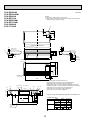
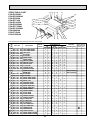
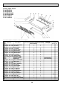
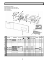
OUTLINES AND DIMENTIONS
INDOOR UNIT
PCA-RP50GA
PCA-RP50GA#1
PCH-P50GAH
Unit : mm
NOTES:
1. Use M10 or W3/8 screws for anchor bolt.
2. When optional drain lift-up mechanism is installed, always provide
upward piping for refrigerant piping.
140
70
320
150
80
17
933 (suspension bolt pitch)
85
983
226
157
15
81 76
Electrical box
180
210
70
904
1000
182
gas
241
(Drainage)
254
506
680
56
Air outlet
liquid
201
Air intake
161
90
918
38
131
161
46 175
1
38 79
Ceiling
6~7
42
32
Electrical box [Front view]
179
1
2
3
4
5
6
7
8
Use the current nuts meeting the pipe size of the outdoor unit.
86
138
171
263
352
525
Drainage pipe connection (26mm I.D.)
Drainage pipe connection (for the left arrangement)
Knockout hole for left drain-piping arrangement
Refrigerant-pipe connection (gas pipe side/flared connection)
Refrigerant-pipe connection (liquid pipe side/flared connection)
Knockout hole for upper drain pipe arrangement
Knockout hole for left drain pipe arrangement
Knockout hole for wiring arrangement
Available pipe size
RP50
P50
LIQUID SIDE :6.35
928
:9.52
When electrical
box is pulled
down
GAS SIDE
:15.88
: Initial flare nut size
15
:9.52
:12.7
:15.88
Unit : mm
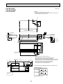
PCA-RP50GA2
PCA-RP50GA2#1
PCA-RP60GA
PCA-RP71GA
PCA-RP60GA#1
PCA-RP71GA#1
PCH-P60GAH
PCH-P71GAH
NOTES:
1. Use M10 or W3/8 screws for anchor bolt.
2. When optional drain lift-up mechanism is installed, always provide
upward piping for refrigerant piping.
140
70
320
150
80
17
1240 (suspension bolt pitch)
85
1290
Electrical box
15
226
210
180
81 76
157
70
1214
182
(liquid)
1310
201
(5/8F gas)
241
(Drainage)
254
506
680
56
Air outlet
Air intake
161
90
1228
38
131
161
525
46 175 1
Ceiling
3879
32
[ Front view ]
6~7
42
179
Electrical box
1
2
3
4
5
6
7
8
Drainage pipe connection (26mm I.D.)
Drainage pipe connection (for the left arrangement)
Knockout hole for left drain-piping arrangement
Refrigerant-pipe connection (gas pipe side/flared connection)
Refrigerant-pipe connection (liquid pipe side/flared connection)
Knockout hole for upper drain pipe arrangement
Knockout hole for left drain pipe arrangement
Knockout hole for wiring arrangement
Use the current nuts meeting the pipe size of the outdoor unit.
86
138
171
263
416
Available pipe size
RP50
LIQUID SIDE :6.35
:9.52
GAS SIDE :12.7
1235
When electrical
box is pulled
down
:15.88
: Initial flare nut size
16
RP60
RP71,P60,P71
:6.35
:9.52
:9.52
:15.88
:15.88
PCA-RP100GA
PCA-RP100GA#1
PCH-P100GAH
Unit : mm
NOTES:
1. Use M10 or W3/8 screws for anchor bolt.
2. When optional drain lift-up mechanism is installed, always provide
upward piping for refrigerant piping.
140
70
320
150
80
18
1240 (suspension bolt pitch)
87
70
16
229
217
270
81 96
207
Electrical box
1214
182
(3/8F liquid)
1310
198
(5/8F, 3/4F gas)
245
(Drainage)
254
506
680
56
Air outlet
Air intake
161
90
1228
Ceiling
6~7
38
192
45
42
236
38 140
1
93
[ Front view ]
160
239
Electrical box
525
86
138
171
263
1
2
3
4
5
6
7
8
Drainage pipe connection (26mm I.D.)
Drainage pipe connection (for the left arrangement)
Knockout hole for left drain-piping arrangement
Refrigerant-pipe connection (gas pipe side/flared connection)
Refrigerant-pipe connection (liquid pipe side/flared connection)
Knockout hole for upper drain pipe arrangement
Knockout hole for left drain pipe arrangement
Knockout hole for wiring arrangement
Use the current nuts meeting the pipe size of the outdoor unit.
Available pipe size
RP100
P100
LIQUID SIDE
687
1235
:9.52
:9.52
:15.88
:19.05
:19.05
GAS SIDE
When electrical
box is pulled
down
:Initial flare nut size
17
Unit : mm
PCA-RP125GA
PCA-RP140GA
PCA-RP125GA#1
PCA-RP140GA#1
PCH-P125GAH
PCH-P140GAH
NOTES:
1. Use M10 or W3/8 screws for anchor bolt.
2. When optional drain lift-up mechanism is installed, always provide
upward piping for refrigerant piping.
140
70
320
150
80
18
1547(suspension bolt pitch)
87
70
16
229
217
270
81 96
207
Electrical box
1524
182
(3/8F liquid)
1620
198
(5/8F, 3/4F gas)
245
(Drainage)
254
506
680
56
Air outlet
Air intake
161
90
1535
[ Front view ]
Ceiling
192
236
Drainage pipe connection (26mm I.D.)
Drainage pipe connection (for the left arrangement)
Knockout hole for left drain-piping arrangement
Refrigerant-pipe connection (gas pipe side/flared connection)
Refrigerant-pipe connection (liquid pipe side/flared connection)
Knockout hole for upper drain pipe arrangement
Knockout hole for left drain pipe arrangement
Knockout hole for wiring arrangement
6~7
38
45
42
160
38 140
1
93
Electrical box
239
1
2
3
4
5
6
7
8
525
687
1545
When electrical
box is pulled
down
86
138
171
263
Use the current nuts meeting the pipe size of the outdoor unit.
Available pipe size
RP125,140 P125,140
LIQUID SIDE
:9.52
:9.52
GAS SIDE
:15.88
:19.05 :19.05
:Initial flare nut size
18
8
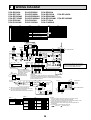
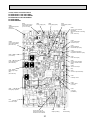
WIRING DIAGRAM
PCA-RP50GA
PCA-RP71GA
PCA-RP50GA#1
PCA-RP71GA#1
PCH-P50GAH
PCH-P100GAH
SYMBOL
MF
MV
DP
DS
TB2
NAME
INDOOR POWER BOARD
INDOOR CONTROLLER BOARD
FUSE (T6.3AL250V)
VARISTOR
CONNECTOR(LOSSNAY)
CONNECTOR(REMOTE SWITCH)
CONNECTOR(HA TERMINAL-A)
CONNECTOR(CENTRALLY CONTROL)
SWITCH (MODEL SELECTION) See Table 1.
SWITCH (CAPACITY CODE) See Table 2.
SWITCH(EMERGENCY OPERATION)
RELAY(DRAIN PUMP)
RELAY(FAN MOTOR)
FAN CONTROL ELEMENT
POWER SUPPLY(I.B)
POWER SUPPLY(R.B)
TRANSMISSION(INDOOR-OUTDOOR)
CAPACITOR(FAN MOTOR)
TB4
TB5,TB6
TH1
TH2
TH5
R.B
P.B CNDK
(RED)
C
THERMAL FUSE(9810A:50GAH/11716A:100GAH
11016A:60,71,125,140GAH)
HEATER
HEATER THERMAL SWITCH
HEATER CONTACTOR
1
2
YLW
ORN
ORN
BRN
BRN
ORN
YLW
ORN
FUSE
D.U.M 1 3 POWER 1 3 POWER 1 3
1 2
1 3 VANE
CND
CNDK
CNP
6
INDOOR/OUTDOOR CN6V
POWER
(ORN)
(RED)
(BLU)
(
)
CN2D(WHT) COMMUNICATION GRN
CN3C(BLU)
X4
X1
ZNR
CN41
CN2L WIRELESS
CN90
CN51
CN32 (WHT)
X4
X1
LED3 LED2 LED1
D.SENSOR INTAKE LIQUID PIPE
CN31
CN29
CN20 CN21
(WHT)
(RED) (WHT) (BLK)
SW1
1 2
1 2
1 2
BLK
BLK
1 2 3
Refer to tables 1
and 2 for service PCB.
REMOCON
CN22
(BLU)
TB4
S1
S2
S3
MV
MV
9
100~140 TYPE
5
5
MV
CNB
Please set the voltage using the remote
controller.
For the setting method, please refer to
the indoor unit Installation Manual.
RU
RECEIVER LED1 LED2 SW2 SW1
W.B
2
1
TO OUTDOOR UNIT
50~71 TYPE
6
6
6
BZ
1 2
BLU
BLU
SW2
BLK
BLK
BCR
RED
WHT
RED
WHT
BLK
DP
FAN 1 3 5
(WHT)
SWE
ON
OFF
H1
26H
88H
NAME
WIRELESS REMOTE CONTROLLER BOARD(OPTION)
RECEIVING UNIT
BUZZER
LED(RUN INDICATOR)
LED(HOT ADJUST)
SWITCH(HEATING ON/OFF)
SWITCH(COOLING ON/OFF)
(OPTION)
1 2 3
I.B
SYMBOL
W.B
RU
BZ
LED1
LED2
SW1
SW2
HEATER
FS1,2
CN2S
(WHT)
1
2 DC13.1V
3
MF
PCA-RP60GA
PCA-RP125GA
PCA-RP140GA
PCA-RP60GA#1
PCA-RP125GA#1 PCA-RP140GA#1
PCH-P71GAH
PCH-P140GAH
NAME
FAN MOTOR
VANE MOTOR
DRAIN-UP MACHINE (OPTION)
DRAIN SENSOR (OPTION)
TERMINAL BLOCK (HEATER) PCH-P.GAH
models only or option for PCA RP.GA(2) models.
TERMINAL BLOCK(INDOOR/OUTDOOR CONNECTING LINE)
TERMINAL BLOCK(REMOTE CONTROLLER
TRANSMISSION LINE )
ROOM TEMP.THERMISTOR
(0/15k, 25/5.4k DETECT)
PIPE TEMP.THERMISTOR/LIQUID
(0/15k, 25/5.4k DETECT)
COND./EVA.TEMP.THERMISTOR
(0/15k, 25/5.4k DETECT)
WIRED REMOTE CONTROLLER BOARD
BLK
WHT
SYMBOL
P.B
I.B
FUSE
ZNR
CN2L
CN32
CN41
CN51
SW1
SW2
SWE
X1
X4
BCR
LED1
LED2
LED3
C
PCA-RP50GA2
PCA-RP100GA
PCA-RP50GA2#1
PCA-RP100GA#1
PCH-P60GAH
PCH-P125GAH
TRANSMISSION WIRES DC12V
1 2
1 2
When installing optional
TB5
drain-up machine disconnect
R.B
the CN31 jumper connector
1 2
and
replace
it
with
the
CN31
TB6
TH2
TH1
TH5
DRAIN SENSOR drain sensor (DS).
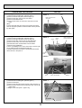
[Servicing]
(WHT) 1 2 3
When installing drain-up
Fasten terminal of the terminal board "TB4"equips lock system.
machine (Optional part).
To remove the fastened terminal, pull it while pressing the protruding
DS
portion (locking lever) of the terminal. The fastened terminal protruding
portion should face upward.
PCH-P50~P140GAH
models only
H1
FS1
FS2
88H
RED
WHT
1
2
RED 5
TB2
1 (Fig.1)
TB2
L
3 RED
N
BLU
RED
BLU
GRN/YLW
POWER SUPPLY
~(1PHASE)
230V 50Hz
GRN/YLW
YLW TB4S1
ORN
S2
ORN
BRN
S3
CN24
1 2 (YLW)
I.B
YLW
YLW
I.B
6
RED
88H
1 GRY
6
5 RED
Table 2
SW2
Table 1
MODELS
PCA-RP.GA
PCH-P.GAH
SW1
Service board
1 2 3 4 5
ON
OFF
MODELS
Service board
PCA-RP50GA
PCH-P50GAH
1 2 3 4 5
PCA-RP50GA2
PCA-RP60GA
PCH-P60GAH
1 2 3 4 5
PCA-RP71GA
PCH-P71GAH
1 2 3 4 5
MODELS
Service board
PCA-RP100GA
1 2 3 4 5
PCA-RP125GA
1 2 3 4 5
PCA-RP140GA
1 2 3 4 5
ON
OFF PCH-P100GAH
ON
OFF PCH-P125GAH
ON
OFF PCH-P140GAH
19
ON
OFF
ON
OFF
ON
OFF
26H
YLW
ORN
HEATER
1. When work to supply power separately to
Indoor and Outdoor unit was applied, refer to Fig 1.
2. For power supply system of this unit,
refer to the caution label located near this diagram.
1 3
L
N
POWER SUPPLY
~(1PHASE)
230V 50Hz
TO OUTDOOR UNIT
1 3
POWER INDOOR/OUTDOOR
CND COMMUNICATION
(ORN)
CN3C
(BLU)
NOTES:
1. Since the outdoor side electric wiring may change be sure to
check the outdoor unit electric wiring for servicing.
2. Indoor and outdoor connecting wires are made with polarities, make
wiring matching terminal numbers (S1, S2, S3).
3. Make sure that the main power supply of the booster heater is
independent.
4. Symbols used in wiring diagram above are,
: Connector,
: Terminal (block).
9
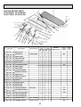
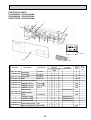
REFRIGERANT SYSTEM DIAGRAM
PCA-RP50GA
PCA-RP71GA
PCA-RP50GA#1
PCA-RP71GA#1
PCH-P50GAH
PCH-P100GAH
PCA-RP50GA2
PCA-RP100GA
PCA-RP50GA2#1
PCA-RP100GA#1
PCH-P60GAH
PCH-P125GAH
PCA-RP60GA
PCA-RP125GA
PCA-RP140GA
PCA-RP60GA#1
PCA-RP125GA#1 PCA-RP140GA#1
PCH-P71GAH
PCH-P140GAH
Unit : mm
Strainer
#50
Heat exchanger
Refrigerant GAS pipe connection
(Flare)
Condenser/evaporator
temperature thermistor
(TH5)
Refrigerant flow in cooling
Refrigerant flow in heating
Refrigerant LIQUID pipe connection
(Flare)
Pipe temperature
thermistor/liquid
(TH2)
Room temperature
thermistor (TH1)
Distributor
with strainer
#50
Strainer
#50
20
10
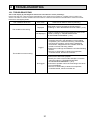
TROUBLESHOOTING
10-1. TROUBLESHOOTING
<Error code display by self-diagnosis and actions to be taken for service (summary)>
Present and past error codes are logged and displayed on the wired remote controller or controller board of outdoor unit.
Actions to be taken for service and the trouble reoccurrence at field are summarized in the table below. Check the contents
below before investigating details.
Unit conditions at service
Error code
Actions to be taken for service (summary)
Displayed
Judge what is wrong and take a corrective action
according to “SELF-DIAGNOSIS ACTION TABLE” (10-2).
The trouble is reoccurring.
Not displayed
Conduct troubleshooting and ascertain the cause of the
trouble according to “TROUBLESHOOTING
BY INFERIOR PHENOMENA ” (10-3).
Consider the temporary defects such as the work of
protection devices in the refrigerant circuit including
compressor, poor connection of wiring, noise and etc.
Re-check the symptom, and check the installation
environment, refrigerant amount, weather when the
trouble occurred, and wiring related.
Reset error code logs and restart the unit after finishing
service.
There is no abnormality in electrical components,
controller boards, and remote controller.
Logged
The trouble is not reoccurring.
Not logged
21
Recheck the abnormal symptom.
Identify the cause of the trouble and take a corrective
action according to “TROUBLESHOOTING
BY INFERIOR PHENOMENA ” (10-3).
Continue to operate unit for the time being if the cause
is not ascertained.
There is no abnormality in electrical components,
controller boards, remote controller etc.
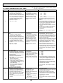
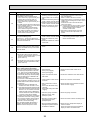
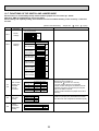
10-2. SELF-DIAGNOSIS ACTION TABLE
Error Code
P1
Note: Refer to the manual of outdoor unit for the details of display
such as F, U, and other E.
Abnormal point and detection method
Cause
Countermeasure
Room temperature thermistor (TH1)
1 The unit is in 3-minute resume
prevention mode if short/open of
thermistor is detected. Abnormal if the
unit does not reset normally after 3 minutes. (The unit returns to normal operation, if it has been reset normally.)
2 Constantly detected during cooling,
drying, and heating operation.
Short: -90: or more
Open: -40: or less
1 Defective thermistor
characteristics
2 Contact failure of connector
(CN20) on the indoor controller
board (Insert failure)
3 Breaking of wire or contact
failure of thermistor wiring
4 Defective indoor controller
board
1–3 Check resistance value of thermistor.
0: 15.0k"
10:
9.6k"
20:
6.3k"
30:
4.3k"
40:
3.0k"
If you put force on (draw or bend) the lead wire
with measuring resistance value of thermistor, breaking of wire or contact failure can be
detected.
2 Check contact failure of connector (CN20)
on the indoor controller board. Refer to 10-6.
Turn the power on again and check restart
after inserting connector again.
4 Check room temperature display on remote
controller.
Replace indoor controller board if there is
abnormal difference with actual room
temperature.
Turn the power off, and on again to operate
after check.
P2
Pipe temperature thermistor/Liquid
(TH2)
1 The unit is in 3-minute resume
prevention mode if short/open of
thermistor is detected. Abnormal if the
unit does not reset normally after 3 minutes. (The unit returns to normal operation, if it has been reset normally.)
2 Constantly detected during cooling,
drying, and heating (except defrosting)
operation
Short: 90: or more
Open: -40: or less
1 Defective thermistor
characteristics
2 Contact failure of connector
(CN44) on the indoor controller board (Insert failure)
3 Breaking of wire or contact
failure of thermistor wiring
4 Defective refrigerant circuit is
causing thermistor temperature of 90: or more or -40:
or less.
5 Defective indoor controller
board
1–3 Check resistance value of thermistor.
For characteristics, refer to (P1) above.
2 Check contact failure of connector (CN44)
on the indoor controller board. Refer to 10-6.
Turn the power on and check restart after
inserting connector again.
4 Check pipe <liquid> temperature with remote
controller in test run mode. If pipe <liquid>
temperature is extremely low (in cooling
mode) or high (in heating mode), refrigerant
circuit may have defective.
5 Check pipe <liquid> temperature with
remote controller in test run mode. If there is
extremely difference with actual pipe <liquid>
temperature, replace indoor controller board.
Turn the power off, and on again to operate
after check.
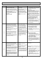
P4
P5
Drain sensor (DS)
1 Suspensive abnormality, if short/open
of thermistor is detected for 30 seconds
continuously.Compressor and indoor fan
will be turned off
2 Short/open is detected for 30 seconds
continuously during suspensive
abnormality.
(The unit returns to normal operation,
if it has normally reset.)
3 Detect the following condition.
• During cooling and drying operation.
• In case that pipe <liquid> temperature room temperature <-10deg
(Except defrosting)
• When pipe <liquid> temperature or
room temperature is short/open
temperature.
• During drain pomp operation.
1 Defective thermistor
characteristics
2 Contact failure of connector
(CN31) on the indoor controller
board. (Insert failure).
3 Breaking of wire or contact
failure of drain sensor wiring.
4 Defective indoor controller board.
Malfunction of drain pump (DP)
1 Suspensive abnormality, if thermistor
of drain sensor is let heat itself and
temperature rises slightly. Compressor
and indoor fan will be turned off.
2 Drain pomp is abnormal if the condition
above is detected during suspensive
abnormality.
3 Constantly detected during drain pump
operation.
1 Malfunction of drain pump
2 Defective drain
Clogged drain pump
Clogged drain pipe
3 Attached drop of water at the
drain sensor
• Drops of drain trickles from
lead wire.
• Clogged filter is causing
wave of drain.
4 Defective indoor controller board.
1–3 Check resistance value of thermistor.
0:......6.0k"
10:....3.9k"
20:....2.6k"
30:....1.8k"
40:....1.3k"
2 Check contact failure of connector (CN31)
on the indoor controller board. Refer to 10-6.
Turn the power on again and check restart
after inserting connector again.
4 Replace indoor controller board if drain
pump operates with the line of drain sensor
connector CN31-1 and 2 is short-circuited,
and abnormality reappears.
Turn the power off, and on again to operate
after check.
22
1 Check if drain-up machine works.
2 Check drain function.
3 Check the setting of lead wire of drain sensor
and check clogs of the filter.
4 Replace indoor controller board if drain
pump operates with the line of drain sensor
connector CN31-1 and 2 is short-circuited
and abnormality reappears.
Refer to 10-6.
Turn the power off, and on again to operate
after check.
Error Code
P6
Abnormal point and detection method
Freezing/overheating protection is working
1 Freezing protection (Cooling mode)
The unit is in 6-minute resume prevention mode if pipe <liquid or condenser/
evaporator> temperature stays under
-15: for 3 minutes, 3 minutes after the
compressor started. Abnormal if it stays
under -15: for 3 minutes again within
16 minutes after 6-minute resume prevention mode.
2 Overheating protection (Heating mode)
The units is in 6 minute resume
prevention mode if pipe <condenser /
evaporator> temperature is detected as
over 70: after the compressor started.
Abnormal if the temperature of over
70: is detected again within 30 minutes
after 6 minute resume prevention mode.
Pipe temperature
<Cooling mode>
Detected as abnormal when the pipe temperature is not in the cooling range 3 minutes after compressor start and 6 minutes
after the liquid or condenser/evaporator
pipe is out of cooling range.
Note 1) It takes at least 9 minutes to
detect.
Note 2) Abnormality P8 is not detected in
drying mode.
Cooling range : -3 °C ] (TH-TH1)
TH: Lower temperature between: liquid
pipe temperature (TH2) and condenser/evaporator temperature (TH5)
TH1: Intake temperature
P8
<Heating mode>
When 10 seconds have passed after the
compressor starts operation and the hot
adjustment mode has finished, the unit is
detected as abnormal when condenser/
evaporator pipe temperature is not in heating range within 20 minutes.
Cause
(Cooling or drying mode)
1 Clogged filter (reduced airflow)
2 Short cycle of air path
3 Low-load (low temperature)
operation out of the tolerance
range
4 Defective indoor fan motor
• Fan motor is defective.
• Indoor controller board is defective.
Countermeasure
(Cooling or drying mode)
1 Check clogs of the filter.
2 Remove shields.
4 Refer to 10-6.
5 Defective outdoor fan control
6 Overcharge of refrigerant
7 Defective refrigerant circuit
(clogs)
5 Check outdoor fan motor.
67 Check operating condition of refrigerant
circuit.
(Heating mode)
1 Clogged filter (reduced airflow)
2 Short cycle of air path
3 Over-load (high temperature)
operation out of the tolerance
range
4 Defective indoor fan motor
• Fan motor is defective.
• Indoor controller board is defective.
5 Defective outdoor fan control
6 Overcharge of refrigerant
7 Defective refrigerant circuit
(clogs)
8 Bypass circuit of outdoor unit
is defective.
(Heating mode)
1 Check clogs of the filter.
2 Remove shields.
1 Slight temperature difference
between indoor room
temperature and pipe <liquid
or condenser / evaporator>
temperature thermistor
• Shortage of refrigerant
• Disconnected holder of pipe
<liquid or condenser /
evaporator> thermistor
• Defective refrigerant circuit
2 Converse connection of
extension pipe (on plural units
connection)
3 Converse wiring of indoor/
outdoor unit connecting wire
(on plural units connection)
4 Defective detection of indoor
room temperature and pipe
<condenser / evaporator>
temperature thermistor
5 Stop valve is not opened
completely.
1~4 Check pipe <liquid or condenser / evaporator> temperature with room temperature display on remote controller and
outdoor controller circuit board.
Pipe <liquid or condenser / evaporator>
temperature display is indicated by setting SW2 of outdoor controller circuit
board as follows.
Note 3) It takes at least 27 minutes to
detect abnormality.
Note 4) It excludes the period of defrosting.
(Detection restarts when defrosting
mode is over.)
Heating range : 3 °C [ (TH5-TH1)
23
4 Refer to 10-6.
5 Check outdoor fan motor.
6~8Check operating condition of refrigerant
circuit.
(
Conduct temperature check with outdoor
controller circuit board after connecting
‘A-Control Service Tool(PAC-SK52ST)’.
)
23Check converse connection of extension
pipe or converse wiring of indoor/outdoor
unit connecting wire.
Error Code
P9
Abnormal point and detection method
Pipe temperature thermistor /
Condenser-Evaporator (TH5)
1 The unit is in 3-minute resume protection mode if short/open of thermistor is
detected. Abnormal if the unit does not
get back to normal within 3 minutes. (The
unit returns to normal operation, if it has
been reset normally.)
2 Constantly detected during cooling,
drying, and heating operation (except
defrosting)
Short: 90: or more
Open: -40: or less
Countermeasure
Cause
1 Defective thermistor
1–3 Check resistance value of thermistor.
For characteristics, refer to (P1) above.
characteristics
2 Check contact failure of connector (CN44)
2 Contact failure of connector
on the indoor controller board.
(CN44) on the indoor controller
Refer to 10-7.
board (Insert failure)
Turn the power on and check restart after
3 Breaking of wire or contact
inserting connector again.
failure of thermistor wiring
4 Operate in test run mode and check pipe
4 Temperature of thermistor is
<condenser / evaporator> temperature with
90: or more or -40: or less
outdoor controller circuit board. If pipe
caused by defective refrigerant
<condenser / evaporator> temperature is
circuit.
extremely low (in cooling mode) or high (in
heating mode), refrigerant circuit may have
5 Defective indoor controller
defect.
board
5 Operate in test run mode and check pipe
<condenser / evaporator> temperature with
outdoor control circuit board. If there is
extreme difference with actual pipe
<condenser / evaporator> temperature,
replace indoor controller board.
There is no abnormality if none of above
comes within the unit.
Turn the power off and on again to operate.
In case of checking pipe temperature
with outdoor controller circuit board,
be sure to connect A-control service
tool (PAC-SK52ST).
(
Remote controller transmission
error(E0)/signal receiving error(E4)
1 Abnormal if main or sub remote controller cannot receive any transmission
normally from indoor unit of refrigerant
address “0” for 3 minutes.
(Error code : E0)
2 Abnormal if sub remote controller could
not receive any signal for 2 minutes.
(Error code: E0)
E0
or
E4
E3
or
E5
1 Abnormal if indoor controller board can
not receive any data normally from
remote controller board or from other
indoor controller board for 3 minutes.
(Error code: E4)
2 Indoor controller board cannot receive
any signal from remote controller for 2
minutes. (Error code: E4)
1 Contact failure at transmission
wire of remote controller
2 All remote controllers are set
as “sub” remote controller.
In this case, E0 is displayed
on remote controller, and E4
is displayed at LED (LED1,
LED2) on the outdoor controller
circuit board.
3 Miswiring of remote controller
4 Defective transmitting receiving
circuit of remote controller
5 Defective transmitting receiving
circuit of indoor controller board
of refrigerant addresses “0”.
6 Noise has entered into the
transmission wire of remote
controller.
1 2 remote controllers are set as
“main.”
(In case of 2 remote controllers)
2 Remote controller is connected
with 2 indoor units or more.
3 Repetition of refrigerant
address
4 Defective transmitting receiving
circuit of remote controller
5 Defective transmitting receiving
circuit of indoor controller board
1 Abnormal if indoor controller board could
not find blank of transmission path.
6 Noise has entered into trans(Error code: E5)
mission wire of remote control2 Indoor controller board receives transler.
mitted data at the same time and compares the received and transmitted data.
Abnormal if these data are judged to
be different 30 continuous times. (Error
code: E5)
Remote controller transmission
error(E3)/signal receiving error(E5)
1 Abnormal if remote controller could not
find blank of transmission path for 6 seconds and could not transmit.
(Error code: E3)
2 Remote controller receives transmitted
data at the same time and compares the
received and transmitted data. Abnormal
if these data are judged to be different
30 continuous times. (Error code: E3)
24
)
1 Check disconnection or looseness of indoor
unit or transmission wire of remote controller.
2 Set one of the remote controllers “main”
if there is no problem with the action above.
3 Check wiring of remote controller.
• Total wiring length: max. 500m
(Do not use cable x 3 or more.)
• The number of connecting indoor units:
max. 16 units
• The number of connecting remote controller: max. 2 units
When it is not the above-mentioned problem of
1~3
4 Diagnose remote controllers.
a) When “RC OK” is displayed,
Remote controllers have no problem.
Turn the power off, and on again to check.
If abnormality generates again, replace
indoor controller board.
b) When “RC NG” is displayed,
Replace remote controller.
c)When “RC E3” or “ERC 00-66” is displayed, noise may be causing abnormality.
* If the unit is not normal after replacing
indoor controller board in group control,
indoor controller board of address “0” may
be abnormal.
1 Set a remote controller to main, and the
other to sub.
2 Remote controller is connected with only one
indoor unit.
3 The address changes to a separate setting.
4~6 Diagnose remote controller.
a) When “RC OK” is displayed, remote controllers have no problem.
Turn the power off,and on again to check.
When becoming abnormal again, replace
indoor controller board.
b)When “RC NG” is displayed, replace
remote controller.
c)When “RC E3” or “ERC 00-66” is displayed, noise may be causing abnormality.
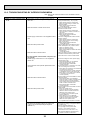
Error Code
Abnornal point and detection method
Cause
Countermeasure
E6
Indoor/outdoor unit communication
error (Signal receiving error)
1 Abnormal if indoor controller board
cannot receive any signal normally for 6
minutes after turning the power on.
2 Abnormal if indoor controller board
cannot receive any signal normally for 3
minutes.
3 Consider the unit abnormal under the following condition: When 2 or more indoor
units are connected to an
outdoor unit, indoor controller board
cannot receive a signal for 3 minutes
from outdoor controller circuit board, a
signal which allows outdoor controller
circuit board to transmit signals.
1 Contact failure, short circuit or,
miswiring (converse wiring) of
indoor/outdoor unit connecting
wire
2 Defective transmitting receiving
circuit of indoor controller board
3 Defective transmitting receiving
circuit of indoor controller board
4 Noise has entered into indoor/
outdoor unit connecting wire.
* Check LED display on the outdoor control
circuit board. (Connect A-control service
tool, PAC-SK52ST.)
Refer to outdoor unit service manual.
1 Check disconnection or looseness of indoor/
outdoor unit connecting wire of indoor unit or
outdoor unit.
Check all the units in case of twin triple
indoor unit system.
2-4 Turn the power off, and on again to check.
If abnormality generates again, replace
indoor controller board or outdoor
controller circuit board.
* Other indoor controller board may have
defect in case of twin triple indoor unit
system.
E7
Indoor/outdoor unit communication
1 Defective transmitting receiving 1-3 Turn the power off, and on again to check.
circuit of indoor controller board
error (Transmitting error)
If abnormality generates again, replace
Abnormal if “1” receiving is detected 30
2 Noise has entered into power
indoor controller board.
supply.
times continuously though indoor controller
board has transmitted “0”.
3 Noise has entered into outdoor
control wire.
Fb
Indoor controller board
Abnormal if data cannot be read normally
from the nonvolatile memory of the indoor
controller board.
E1
or
E2
PA
1 Defective indoor controller
board
Remote controller control board
1 Defective remote controller
1 Abnormal if data cannot be read normally from the nonvolatile memory of the
remote controller control board.
(Error code: E1)
1 Replace indoor controller board.
1 Replace remote controller.
2 Abnormal if the clock function of remote
controller cannot be operated normally.
(Error code: E2)
Forced compressor stop
(due to water leakage abnormality)
1 When the intake temperature subtracted
with liquid pipe temperature is less than
-10:, drain sensor is detected whether
it is soaked in the water or not at the interval
of 90 seconds. (Drain pump will start operating
when the drain sensor is detected to be
soaked in the water.)
2 The unit has a water leakage abnormality
when the following conditions, a and b, are
satisfied while the above-mentioned detection
is performed.
a) The drain sensor is detected to be
soaked in the water 10 times in a row.
b) The intake temperature subtracted with
liquid pipe temperature is detected to be
less than -10: for a total of 30 minutes.
(When the drain sensor is detected to
be NOT soaked in the water, the detection
record of a and b will be cleared.)
3 The drain sensor detection is performed
in operations other than cooling. (When
the unit stops operating, during heating
or fan operation, when the unit stops
because of some abnormality)
*Once the water leakage abnormality is
detected, abnormality state will not be
released until the main power is reset.
1 Drain pump trouble
1 Check the drain pump.
2 Drain defective
· Drain pump clogging
· Drain pipe clogging
2 Please confirm whether water can be
drained.
3 Open circuit of drain sensor
side heater
3 Confirm the resistance of the drain sensor.
4 Contact failure of drain sensor 4 Check the connector contact failure.
connector
5 Dew condensation on drain
sensor
· Drain water descends along
lead wire.
· Drain water waving due to filter
clogging.
5 Check the drain sensor leadwire mounted.
Check the filter clogging
6 Extension piping connection
difference at twin, triple,
quadruple system.
6 Check the piping connection.
7 Mis-wiring of indoor/ outdoor
connecting at twin, triple,
quadruple system.
7 Check the indoor/ outdoor connecting wires.
8 Room temperature thermistor /
liquid pipe temperature thermistor detection is defective.
8 Check the room temperature display of
remote controller.
Check the indoor liquid pipe temperature
display of outdoor controller board.
25
10-3. TROUBLESHOOTING BY INFERIOR PHENOMENA
Note: Refer to the manual of outdoor unit for the detail of remote
controller.
Phenomena
(1)LED2 on indoor controller board
is off.
Cause
• When LED1 on indoor controller board is also off.
1 Power supply of rated voltage is not supplied to outdoor unit.
2 Defective outdoor controller circuit board.
3 Power supply of 220~240V is not supplied to indoor
unit.
4 Defective indoor power board.
5 Defective indoor controller board.
(For the separate indoor/outdoor unit power supply system)
1 Power supply of 220~240V AC is not supplied to
indoor unit.
2 The connectors of the optional replacement kit are
not used.
3 Defective indoor controller board.
4 Defective indoor power board.
• When LED1 on indoor controller board is lit.
1 Mis-setting of refrigerant address for outdoor unit
(There is no unit corresponding to refrigerant
address “0”.)
Countermeasure
1 Check the voltage of outdoor power
supply terminal block (L, N) or (L3, N).
• When AC 220~240V is not detected.
Check the power wiring to outdoor unit
and the breaker.
• When AC 220~240V is detected.
—Check 2 (below).
2 Check the voltage between outdoor
terminal block S1 and S2.
• When AC 220~240V is not detected.
Check the fuse on outdoor controller circuit board.
Check the wiring connection.
• When AC 220~240V is detected.
—Check 3 (below).
3 Check the voltage between indoor terminal
block S1 and S2.
• When AC 220~240V is not detected.
Check indoor/outdoor unit connecting
wire for mis-wiring.
• When AC 220~240V is detected.
—Check 4 (below).
4 Check voltage output from CN2S on indoor
power board (DC13.1V). Refer to 10-6-1.
• When no voltage is output.
Check the wiring connection.
• When output voltage is between DC12.5V
and DC13.7V.
—Check 5 (below).
5 Check the wiring connection between indoor
controller board and indoor power board.
Check the fuse on indoor controller board.
1 Check the voltage of indoor power supply
terminal block (L,N).
• When AC220~240V is not detected.
Check the power supply wiring.
• When AC220~240V is detected.
-Check 2 (below).
2 Check that there is no problem in the method of connecting the connectors.
• When there are problems in the method of
connecting the connectors.
Connect the connector correctly referring
to installation manual of an optional kit.
• When there is no problem in the method
of connecting the connectors.
-Check 3 (below).
3 Check voltage output from CNDK on indoor
controller board.
• When AC220~240V is not detected.
Check the fuse on indoor controller board.
Check the wiring connection between
indoor power supply terminal block and
CND on indoor controller board.
• When AC220~240V is detected.
-Check 4 (below).
4 Check voltage output from CN2S on indoor
power board.
• When no voltage output.
Check the wiring connection between
CNDK on indoor controller board and
CNSK on indoor power board.
If no problem are found,indoor power
board is defective.
• When DC12.5~13.7V is detected.
Check the wiring connection between
CN2S on indoor power board and
CN2D on indoor power board.
If no problem are found,indoor controller
1 Reconfirm the setting of refrigerant address
for outdoor unit
Set the refrigerant address to “0”.
(For grouping control system under
which 2 or more outdoor units are
connected, set one of the units to “0”.)
Set refrigerant address using SW1 (3-6)
on outdoor controller circuit board.
26
Note: Refer to the manual of outdoor unit for the detail of remote
controller.
Phenomena
(2)LED2 on indoor controller board
is blinking.
Cause
Countermeasure
• When LED1 on indoor controller board is also blinking. Check indoor/outdoor unit connecting wire
Connection failure of indoor/outdoor unit connecting for connection failure.
wire
• When LED1 is lit.
1 Check the connection of remote controller wires in case of twin triple indoor
1 Mis-wiring of remote controller wires
unit system. When 2 or more indoor units
Under twin triple indoor unit system, 2 or more indoor
are wired in one refrigerant system,
units are wired together.
connect remote controller wires to one of
those units.
2 Refrigerant address for outdoor unit is wrong or not 2 Check the setting of refrigerant address
in case of grouping control system.
set.
If there are some units whose refrigerant
Under grouping control system, there are some units
addresses are 0 in one group, set one of
whose refrigerant address is 0.
the units to 0 using SW1 (3-6) on outdoor
controller circuit board.
34 Remove remote controller wires and
3 Short-cut of remote controller wires
check LED2 on indoor controller board.
4 Defective remote controller
• When LED2 is blinking, check the shortcut of remote controller wires.
• When LED2 is lit, connect remote
controller wires again and:
if LED2 is blinking, remote controller
is defective; if LED2 is lit, connection
failure of remote controller terminal
block etc. has returned to normal.
(3)Upward/downward vane
performance failure
1 The vane is not downward during defrosting and heat 1 Normal operation (The vane is set to
preparation and when the thermostat is OFF in HEAT
horizontal regardless of remote control.)
mode. (Working of COOL protection function)
2 Vane motor does not rotate.
2 Check 2 (left).
• Defective vane motor
• Check the vane motor. (Refer to “How
• Breaking of wire or connection failure of connector
to check the parts”.)
• Up/down vane setting is “No vanes”.
• Check for breaking of wire or connection failure of connector.
• Check “Up/down vane setting”. (Unit
function selection by remote controller).
3 Upward/downward vane does not work.
3 Normal operation (Each connector on
• The vane is set to fixed position.
vane motor side is disconnected.)
(4)Receiver for wireless remote
controller
1 Weak batteries of wireless remote controller.
1 Replace batteries of wireless remote controller.
2 Contact failure of connector (CNB) on wireless
2~4
remote controller board.
Check contact failure of each connector.
(Insert failure)
If no problems are found of connector,
3 Contact failure of connector (CN90) on indoor conreplace indoor controller board.
troller board.(Insert failure)
When the same trouble occurs even if
4 Contact failure of connector between wireless remote
indoor controller board is replaced,
controller board and indoor controller board.
replace wireless remote controller
board.
27
10-4. When wired remote controller or indoor unit micro computer troubles
1. If there is not any other wrong when trouble occurs, emergency operation starts as the indoor controller board switch (SWE)
is set to ON.
During the emergency operation the indoor unit is as follows;
(1) Indoor fan high speed operation
(2) Drain-up machine operation(Option)
2. When emergency operating for COOL or HEAT, setting of the switch (SWE) in the indoor controller board and outdoor unit
emergency operation are necessary.
3. Check items and notices as the emergency operation
(1) Emergency operation cannot be used as follows;
• When the outdoor unit is something wrong.
• When the indoor fan is something wrong.
• When drain over flow protected operation is detected during self-diagnosis. (Error code : P5)
(2) Emergency operation will be serial operation by the power supply ON/OFF.
ON/OFF or temperature, etc. adjustment is not operated by the remote controller.
(3) Do not operate for a long time as cold air is blown when the outdoor unit starts defrosting operation during heat emergency operation.
(4) Cool emergency operation must be within 10 hours at most. It may cause heat exchanger frosting in the indoor unit.
(5) After completing the emergency operation, return the switch setting, etc. in former state.
(6) Since vane does not work at emergency operation, position the vane manually and slowly.
28
10-5. HOW TO CHECK THE PARTS
PCA-RP50/60/71/100/125/140GA
PCA-RP50/60/71/100/125/140GA#1
PCA-RP50GA2
PCA-RP50GA2#1
PCH-P50/60/71/100/125/140GAH
Parts name
Check points
Room temperature
thermistor
(TH1)
Disconnect the connector then measure the resistance with a tester.
(At the ambient temperature 10~30)
Pipe temperature
thermistor
(TH2)
Condenser/evaporator
temperature thermistor
(TH5)
Fan motor
Relay connector
1
Red
2 White
3 Black
1
2
Normal
Abnormal
4.3k~9.6k
Open or short
Measure the resistance between the terminals using a tester.
(Winding temperature 20)
Normal
Motor terminal
or
Relay connector
50GA
50GA2
60, 71
100
125, 140
Red–Black
70.6
45.0
43.7
20.4
White–Black
69.6
44.8
55.3
20.7
3
Protector
OFF : 130$5
ON : 80$20
Vane motor
Red
Pink
M
Brown–Blue
Red–Orange
50GA2, 60, 71
186~214
140~160
Open or short
Abnormal
Pink
Open or short
Red–Pink
Normal
Connector
Abnormal
100, 125, 140
M
Red–Yellow
Orange
50GA
Abnormal
Brown–Yellow
Yellow Brown Blue
Normal
Connector
Orange
(Refer to the next pege for a detail.)
Red–Blue
Red
Yellow
Blue
Open or short
140~160
Red–Orange
Red–Pink
Measure the resistance of each heater element with a tester.
(At the ambient temperature 20)
Heater
(Only PCH)
Normal
50
Drain-up
mechanism (Option)
60, 71
100
13.7
9.1
7.1
6.4
0.467kW 80V
0.7kW 80V
0.9kW 80V
1.0kW 80V
Measure the resistance between the terminals with a tester.
(Winding temperature 20)
Gray
1
Normal
Abnormal
3
195
Open or short
Gray
Contactor
125,140
Measure the resistance between the terminals with a tester.
(Only PCH)
Normal
Abnormal
50~140
6
88H
160
1
Open or short
29
Abnormal
Open or short
<Thermistor Characteristic graph>
< Thermistor for lower temperature >
Thermistor R0=15k ± 3%
Fixed number of B=3480 ± 2%
Rt=15exp { 3480(
0:
10:
20:
25:
30:
40:
1
273+t
50
40
Resistance (k)
Thermistor for
lower temperature
Room temperature thermistor(TH1)
Pipe temperature thermistor(TH2)
Condenser/evaporator temperature
thermistor(TH5)
1 )}
273
15k
9.6k
6.3k
5.4k
4.3k
3.0k
30
20
10
0
-20 -10 0 10 20 30 40 50
Temperature ()
10-6.TEST POINT DIAGRAM
10-6-1. Power board
PCA-RP50GA
PCA-RP50GA#1
PCA-RP60GA
PCA-RP60GA#1
PCA-RP71GA
PCA-RP71GA#1
PCA-RP100GA
PCA-RP100GA#1
PCA-RP125GA
PCA-RP125GA#1
PCA-RP140GA
PCA-RP140GA#1
PCA-RP50GAH
PCA-RP60GAH
PCA-RP71GAH
PCA-RP100GAH
PCA-RP125GAH
PCA-RP140GAH
PCA-RP50GA2
PCA-RP50GA2#1
CN2S
Connect to the indoor controller board (CN2D)
Between 1 to 3 12.6-13.7V DC (Pin1 (+))
CNSK
Connect to the indoor controller board
(CNDK)
Between 1 to 3 220-240V AC
30
10-6-2. Indoor controller board
PCA-RP50/60/71/100/125/140GA
PCA-RP50/60/71/100/125/140GA#1
PCH-P50/60/71/100/125/140GAH
PCA-RP50GA2
PCA-RP50GA2#1
CN3C
Transmission (Indoor/
outdoor)
(0~24V DC)
CN2D
Connect to the indoor
power board (CN2S)
(12.5~13.7V DC)
LED1
Power supply (I.B)
LED2
Power supply (R.B)
LED3
Transmission (Indoor/
outdoor)
CN22
Connect to the terminal
block(TB5)
(Remote controller connecting
wire)
(10.4~14.6V DC)
CN20
Room temperature
thermistor (TH1)
CNDK
Connect to the indoor
power board (CNSK)
(220~240V AC)
CN21
Pipe temperature
thermistor/Liquid (TH2)
CN29
Condenser/evaporator
temperature thermistor (TH5)
FUSE
(6.3 A 250 V)
CN31
Drain sensor (DS)
CN90
Connect to the wireless
remote controller board
(CNB)
CND
Power supply input
(220~240V AC)
CN6V
Vane motor output
(MV)
CNP
Drain-pump output
(DP)
(220~240V AC)
CN41
Connector (HA terminal-A)
CN51
Centrally control
CN24
Heater output
(12V DC)
SWE
Emergency operation
CN2L
Connector
(LOSSNAY)
FAN
Fan motor output
Jumper wire J41, J42
Pair number setting with
wireless remote controller
31
SW2
Capacity setting
SW1
Model setting
10-7. FUNCTIONS OF DIP SWITCH AND JUMPER WIRE
Each function is controlled by the dip switch and the jumper wire on control p.c. board.
SW1 and SW2 are equipped only for service parts.
Model setting and capacity setting are memorized in the nonvolatile memory of the control p.c. board of
the unit.
(Marks in the table below)
Jumper wire
Functions
Setting by the dip switch and jumper wire
Jumper wire (
: Short
: Open)
Remarks
For service board
SW1
Model
settings
1
2
3
4
ON
OFF
MODELS
SW2
Capacity
settings
J41
J42
Pair number
setting with
wireless
remote
controller
JP1
Unit type
setting
JP3
Indoor
controller
board type
setting
5
Service board
PCA-RP50GA
PCH-P50GAH
1 2 3 4 5
PCA-RP50GA2
PCA-RP60GA
PCH-P60GAH
1 2 3 4 5
PCA-RP71GA
PCH-P71GAH
1 2 3 4 5
PCA-RP100GA
PCH-P100GAH
1 2 3 4 5
PCA-RP125GA
PCH-P125GAH
1 2 3 4 5
PCA-RP140GA
PCH-P140GAH
1 2 3 4 5
ON
OFF
ON
OFF
ON
OFF
ON
OFF
ON
OFF
ON
OFF
<Initial setting>
Wireless remote controller: 0
Control PCB: (for both J41 and J42)
Four pair number settings are supported.
The pair number settings of the wireless remote
controller and indoor control PCB (J41/J42) are
given in the table on the left.
(' ' in the table indicates the jumper line is disconnected.)
Wireless remote Control PCB setting
controller setting
J41
J42
0
1
2
3~9
Model
Without TH5
With TH5
JP1
Indoor controller board type
For product
Service parts
There is no jumper (JP1) because these models
have the cond./eva. temperature thermistor (TH5).
JP3
32
11
SPECIAL FUNCTION
11-1. ROTATION FUNCTION(AND BACK-UP FUNCTION, 2ND STAGE CUT-IN FUNCTION)
For PCA-RP50/60/71/100/125/140GA#1,PCA-RP50GA2#1
11-1-1. Operation
(1) Rotation function (and Back-up function)
• Outline of functions
· Main and sub unit operate alternately according to the interval of rotation setting.
w Main and sub unit should be set by refrigerant address.(Outdoor Dip switch setting)
Refrigerant address"00"
Main unit
Refrigerant address"01"
Sub unit
· When error occurrs to one unit, another unit will start operation.(Back-up function)
• System constraint
· This function is available only by the grouping control system(INDOOR UNIT : OUTDOOR UNIT=1:1) of 2 refrigerant
groups.(Refer to Fig. 1)
· Main indoor unit should be connected for wired remote controller and the transmission line(TB5) for main and sub unit
should also be connected. (Refer to Fig. 1)
(This function cannot be set by wireless remote controller.)
· Set refrigerant address of each unit.(Dip switch on the outdoor unit···Refrigerant address 00/01)
Fig. 1
Operation pattern
Refrigerant address
"00"
Refrigerant address
"01"
[Back-up function only]··· Request code number "312"
Error occurs on main unit.
Main
Sub
Start operation
Main
unit
IC-1
Sub
unit
IC-2
Run
Abnormal condition
Stop
Run
OC-2
OC-1
Main
unit
3(2)
3(2)
IC-2
IC-1
2
Sub
unit
2
[Rotation function] & [Back-up function]··· Request code number "313~318"
RC
Start operation
Main
unit
IC-1
Sub
unit
IC-2
Main
Sub
Sub
Error occurs on main unit.
Main Main
Sub
Abnormal condition
Run
Stop
Run
Stop
Run
Stop
1~28 days
OC : Outdoor unit
IC : Indoor unit
RC : Wired remote controller
Run
1~28 days
(Ex:When the request code number is "313", each unit operates alternately in daily cycle.)
Note:
· When the uint is restarted to operate after turning off the power or OFF operation, the unit which was operating will start
operation.
· To operate the main unit, refer to the 11-1-2. and set the requet code No. which is not the same as the current one, and set
again the former request code No.
(2) 2nd stage cut-in function
Outline of functions
· Number of operating units is determined according to the room temperature and set point.
· When room temperature becomes higher than set point, standby unit starts.(2 units operation)
· When room temperature falls below set point -4:, standby unit stops.(1 unit operation)
System constraint
[2nd stage cut-in function]··· Request code number "322~324"
· This function is available only in rotation operation and back-up function in
Room temp. Set point
Room temp. < Set point -4
Start operation
Sub unit start operation
Sub unit stop
cooling mode.
Main
unit
IC-1
Run
Sub
unit
IC-2
Stop
33
Run
Stop
11-1-2. How to set rotation function(Back-up function, 2nd stage cut-in function)
You can set these functions by wired remote controller.(Maintenance monitor)
NOTICE
Both main and sub unit should be set in same setting.
Every time replacing indoor controller board for servicing, the function should be set again.
(1) Request Code List
Rotation setting
Setting No.
(Request code)
No.1
(310)
No.2
(311)
No.3
(312)
No.4
(313)
No.5
(314)
No.6
(315)
No.7
(316)
No.8
(317)
No.9
(318)
Initial
setting
Setting contents
Monitoring the request code of current setting.
Rotation and Back-up OFF (Normal group control operation)
Back-up function only
Rotation ON (Alternating interval = 1day) and back up function
Rotation ON (Alternating interval = 3day) and back up function
Rotation ON (Alternating interval = 5day) and back up function
Rotation ON (Alternating interval = 7day) and back up function
Rotation ON (Alternating interval = 14day) and back up function
Rotation ON (Alternating interval = 28day) and back up function
2nd stage cut-in setting
Setting No.
(Request code)
No.1
(320)
No.2
(321)
No.3
(322)
No.4
(323)
No.5
(324)
Initial
setting
Setting contents
Monitoring the request code of current setting.
Cut-in function OFF
Cut-in Function ON(Set point = Set temp.+ 4°C(7.2°F))
Cut-in Function ON(Set point = Set temp.+ 6°C(10.8°F))
Cut-in Function ON(Set point = Set temp.+ 8°C(14.4°F))
34
(2) Setting method of each function by wired remote controller
B: Refrigerant address
C: Data display area
D: Request code display area
1. Stop operation(
).
2. Press the TEST button () for 3 seconds so that [Maintenance mode] appears on the screen ().
After a while, [00] appears in the refrigerant address number display area.(at )
3. Press the CHECK button () for 3 seconds to switch to [Maintenance monitor].
Note) It is not possible to switch to [Maintenance monitor] during data request in maintenance mode
(i.e., while “----” is blinking) since no buttons are operative.
[----] appears on the screen () when [Maintenance monitor] is activated.
(The display () now allows you to set a request code No.)
4. Press the [TEMP (
[ScreenB]
5. Press the [CLOCK (
and
)] buttons () to select the desired refrigerant address.
and
)] buttons () to set the desired request code No.(“311~318”, “321~324”)
6. Press the FILTER button () to perform function setting.
If above setting operations are done correctly, "Request code number will appear in data display area.()
[Example: When the "311" of "Request code number" is set, [311] appears on the screen.()]
[Refererence]
You can check current "request code number" setting by setting the "request code number"(“310” or “320”) and
pressing the FILTER button.()
[Example: When the current setting is "Setting No.2(Request code 311)", [311] appears on the screen.()]
7. To return to normal mode, press the ON/OFF button (
).
35
12
DISASSEMBLY PROCEDURE
PCA-RP50/60/71/100/125/140GA
PCA-RP50/60/71/100/125/140GA#1
PCA-RP50GA2
PCA-RP50GA2#1
PCH-P50/60/71/100/125/140GAH
OPERATING PROCEDURE
PHOTOS&ILLUSTRATIONS
1. Removing the air intake grille
(1) Slide the intake grille holding 2 knobs backward to open
the intake grill.
(2) When the intake grille left open, push the stoppers on the
rear 2 hinges to pull out the intake grille.
Figure 1
Intake grill
slide
Intake grill
Holding knobs
Hinges
Pull out the intake grill
2. Removing the electrical box
(1) Remove the air intake grille. (See the figure 1)
(2) Remove the screw from the beam and remove the beam.
(3) Remove the screws from the electrical cover, and remove
the electrical cover.
(4) Disconnect CN6V, CN21 and CN29.
(5) Remove the screws from the electrical box and pull out
the electrical box.
Figure 2
Beam
Slide to the left
<Electrical parts in the electrical box>
Terminal block (for indoor / outdoor connecting line)
Terminal block (for electric heater : PCH only)
Terminal block (for remote controller)
Fan motor capacitor
Indoor control board
Relay (PCH only)
Power board
Screw(electrical cover)
Clamp
Electrical cover
Screw(electrical box)
Photo 1
Fan motor
capacitor
Relay (PCH only)
Power board
Indoor
control
board
36
Terminal
block
Terminal
(remote control)
block
Terminal
(Indoor / outdoor
block
(Electric heater) connecting line)
OPERATING PROCEDURE
PHOTOS&ILLUSTRATIONS
3. Removing the fan motor
(1) Remove the intake grille. (See the figure 1)
(2) Disconnect the fan motor connector.
(3) Remove screws for removing the motor guard.
(4) Remove screws for removing the fan guard.
(5) Remove the screw for removing the motor support at both
left and right side.
(6) Loosen the set screws at the fan motor side of the connecting joint.
(7) Slide the fan motor to the left side and pull it out.
Photo 2
Motor guard
Screws
Motor
Set screws
Motor support
4. Removing the sirocco fan
(1) Remove the air intake grille. (See the figure 1)
(2) Remove 1 beam.
(3) Remove screws for removing the motor guard.
(4) Remove screws for removing the fan guard.
(5) Remove the lower casing while pressing the stoppers at
upper side of the casing.
(6) Loosen the set screws at the connecting joint.
(7) Remove the sirocco fan and shaft together by sliding the
shaft to the left.
Connecting joint
Photo 3
Fan guard
Motor guard
(Note)
Make sure that the upper side casing is snapped to the fan
plate securely with catch.
Sirocco fan
Motor
Casing
Bearing
Connecting joint
5. Removing the side panel
(1) Remove the air intake grille. (See the figure 1)
(2) Remove the screw from the side panel, and remove the
side panel by sliding the panel to the front.
Figure 3
Side panel
Sliding the panel
to the front
Screw
37
OPERATING PROCEDURE
PHOTOS
6. Removing the vane motor
(1) Remove the air intake grille. (See the figure 1)
(2) Remove the left side panel. (See the figure 3)
(3) Remove the relay connector of vane motor.
(4) Remove the electrical box.
(5) Remove the screws of vane motor, then remove vane
motor.
(Note)
Connect the lead wires and connectors properly and place
them in the proper position so that the wires are not pinched
by other parts.
Photo 4
Screw
Relay connector of the
vane motor
Vane motor
7. Removing the Indoor coil thermistor
(1) Remove the air intake grille. (See the figure 1)
(2) Remove the right side panel. (See the figure 3)
(3) Remove the relay connector of the pipe thermistor.
(4) Remove the screw, and remove the check panel.
(5) Extract the indoor coil thermistor from the holder.
<Caution for the installation>
There is a possibility for the short circuit when connector gets
wet by water through the thermistor lead wire.
Therefore, lead wire of the indoor coil thermistor should be
tied as shown in the photo 6.
Photo 5
Screw
Check
panel
Relay connector of
the pipe thermistor
Left side
panel
Photo 6
Hold
8. Removing the Under panel
(1) Remove the air intake grille. (See the figure 1)
(2) Remove the beam.
(3) Remove the side panel (right and left). (See the figure 3)
(4) Remove the 9 screws of the under panel, then remove the
under panel.
w Weight of the under panel : approx. 2kg.
Photo 7
Indoor coil thermistor
Screws
Under panel
38
Clamp
OPERATING PROCEDURE
PHOTOS
9. Removing the drain pan
(1) Remove the air intake grille. (See the figure 1)
(2) Remove the beam.
(3) Remove the side panels of right and left. (See the figure 3)
(4) Remove the under panel. Remove the screws of the right
and left side drain pan.
(5) Remove the 2 insulations in centre of the drain pan, and
after removing the 2 screws, remove the drain pan.
Photo 8
(Note)
Please aware that there might be drain left in the drain pan
when you remove the drain pump (option).
Screw
10. Removing the guide vane
(1) Remove the intake grille. (See the figure 1)
(2) Remove the beam.
(3) Remove the side panels on right and left. (See the figure 3)
(4) Remove the under panel. (See the photo 7)
(5) Remove the drain pan. (See the photo 8)
(6) Remove the screw from the guide vane, then remove the
guide vane.
Drain pan
Screw
Photo 9
Drain pan
11. Removing the Auto vane
(1) Remove the intake grille. (See the figure 1)
(2) Remove the left side panel. (See the figure 3)
(3) Remove the left side box.
(4) Remove the under panel.
(5) Remove the screw from the auto vane.
(6) Slide the auto vane to the right side and pull the auto
vane out.
Screw
(Insulation)
Screw
Guide vane
Photo 10
Screw
Auto vane
39
OPERATING PROCEDURE
PHOTOS
12. Removing the electric heater. (PCH only)
(1) Remove the air intake grille. (See the figure 1)
(2) Remove the beam.
(3) Remove the electrical box cover and disconnect the connector (6P red) of the heater.
(4) Loosen 2 clamps for the heater lead wires.
(5) Remove the side panel (right and left). (See the figure 3)
(6) Remove the under panel. (See the photo 7)
(7) Remove the drain pan. (See the photo 8)
(8) Remove the 3 screws from the service panel.
(9) Pull out the heater with the service panel.
Photo 11
Screws
Clamp
Service
panel
Connector
(heater)
Electrical
box
13. Removing the heat exchanger.
(1) Remove the air intake grille. (See the figure 1)
(2) Remove the beam.
(3) Remove the side panel (right and left). (See the figure 3)
(4) Disconnect the relay connector of the pipe thermistor.
(5) Remove the under panel. (See the photo 7)
(6) Remove the drain pan. (See the photo 8)
(7) Unscrew the screw of the pipe cover, and remove the pipe
cover.
(8) Unscrew the screw of the pipe support, and remove the
pipe support.
(9) Unscrew the screw of the heat exchanger, and remove
the heat exchanger.
Remove the heat exchanger with care. Since this is quite
heavy, removing work should be done with more than 2
people.
wWeight of heat exchanger : approx. 5.3kg
40
Photo 12
Pipe
support
Screws
Pipe cover
Screws
Heat
exchanger
13
PARTS LIST(non-RoHS compliant)
FAN AND HEATER PARTS
PCH-P50GAH
PCA-RP50GA
18
17
16
15
2
3
1
4
5
14
13
2
12
3
6
11
7
8
10
9
Q'ty / set
No.
Parts No.
Parts Name
Specifications
PCH-
PCA-
P50GAH
RP50GA
1
R01 17J 130 MOTOR LEG
1
1
2
R01 17J 110 CASING
2
2
3
R01 17J 114 SIROCCO FAN
2
2
4
T7W 19J 675 FAN GUARD
1
1
5
R01 E26 202 ROOM TEMPERATURE THERMISTOR
1
1
6
R01 43E 126 PIECE (MOTOR)
1
1
7
R01 17J 220 FAN MOTOR
1
1
8
R01 17J 524 DRAIN PLUG
1
1
9
T7W 17J 675 FAN GUARD
1
1
10 R01 A14 529 DRAIN PAN ASSY
1
1
11 T7W 18J 675 FAN GUARD
1
1
12 R01 46K 700 THERMAL SWITCH
13
D09B4P54MS
OFF:50 ON:35
3
R01 20J 303 INSULATOR
1
14 T7W 23J 300 HEATER ELEMENT
80V 466W
Wiring
Diagram
Symbol
TH1
MF
26H
1
R01 18J 303 INSULATOR
Remarks
(Drawing No.)
H1
3
15 R01 17J 202 PIPE TEMPERATURE THERMISTOR
1
1
TH2
16 R01 E27 202 CONDENSER / EVAPORATOR TEMPERATURE THERMISTOR
1
1
TH5
17
R01 E38 480 HEAT EXCHANGER
1
T7W K00 480 HEAT EXCHANGER
18 R01 P02 706 THERMAL FUSE
1
250V 98 10A
41
1
FS1,2
Recommended
Q'ty
FAN AND HEATER PARTS
PCH-P60GAH, PCA-RP60GA
PCH-P71GAH, PCA-RP71GA
22
21
23
20
19
1
2
3
18
17
4
16
15
14
5
6
7 5
8
13
9
10·11
12
Q'ty / set
No.
Parts No.
Parts Name
Specifications
PCHP60 P71
GAH GAH
PCARP60 RP71
GA GA
Remarks
(Drawing No.)
Wiring
Diagram
Symbol
1
1
1
1
1
1
1
1
R01 700 116 SHAFT JOINT
1
1
1
1
4
R01 43E 126 PIECE (MOTOR)
1
1
1
1
5
R01 29J 114 SIROCCO FAN
2
2
2
2
6
T7W 20J 675 FAN GUARD
1
1
1
1
7
R01 E26 202 ROOM TEMPERATURE THERMISTOR
1
1
1
1
8
R01 29J 100 SHAFT (FAN)
1
1
1
1
9
T7W 21J 675 FAN GUARD
2
2
2
2
10 R01 E00 103 SLEEVE BEARING
1
1
1
1
11 R01 29J 145 BEARING SUPPORT
1
1
1
1
12 R01 17J 524 DRAIN PLUG
1
1
1
1
13 R01 A15 529 DRAIN PAN ASSY
1
1
1
1
14 T7W 18J 675 FAN GUARD
1
1
1
1
15 R01 17J 110 CASING
3
3
3
3
16 R01 33J 114 SIROCCO FAN
1
1
1
1
1
1
3
3
3
3
19 R01 17J 202 PIPE TEMPERATURE THERMISTOR
1
1
1
1
TH2
20 R01 E27 202 CONDENSER / EVAPORATOR TEMPERATURE THERMISTOR
1
1
1
1
TH5
1
1
1
R01 29J 130 MOTOR LEG
2
T7W 30J 762 FAN MOTOR
3
17
R01 20J 303 INSULATOR
R01 30J 303 INSULATOR
18 T7W 30J 300 HEATER ELEMENT
21
DO9C4P70MS
80V 700W
R01 H00 480 HEAT EXCHANGER
MF
TH1
H1
1
1
T7W K01 480 HEAT EXCHANGER
22 T7W 23J 706 THERMAL FUSE
110 16A 250V
1
1
FS1,2
23 R01 46K 700 THERMAL SWITCH
OFF:50 ON:35
1
1
26H
42
Recommended
Q'ty
FAN AND HEATER PARTS
PCH-P100GAH
PCA-RP100GA
23
21
22
20
1
19
2
3
4
18
5
17
16
6
15
7
14
8
5
13
9
12
10·11
Q'ty / set
No.
Parts No.
Parts Name
Specifications
PCH-
PCA-
P100GAH RP100GA
1
2
3
R01 43E 126 PIECE (MOTOR)
R01 35J 130 MOTOR LEG
R01 35J 220 FAN MOTOR
R01 700 116 SHAFT JOINT
D10B4P90MS
1
1
1
1
1
1
1
1
R01 35J 114 SIROCCO FAN
T7W 22J 675 FAN GUARD
2
2
1
1
R01 E26 202 ROOM TEMPERATURE THERMISTOR
R01 29J 100 SHAFT
1
1
1
1
T7W 23J 675 FAN GUARD
10 R01 E00 103 SLEEVE BEARING
11 R01 35J 145 BEARING SUPPORT
2
2
1
1
1
1
12 R01 17J 524 DRAIN PLUG
13 R01 A16 529 DRAIN PAN ASSY
14 T7W 24J 675 FAN GUARD
1
1
1
1
1
1
15 R01 35J 110 CASING
16 R01 39J 114 SIROCCO FAN
R01 20J 303 INSULATOR
17
R01 36J 303 INSULATOR
18 T7W 39J 300 HEATER ELEMENT
3
3
1
1
4
5
6
7
8
9
Remarks
(Drawing No.)
Wiring RecomDiagram mended
Symbol Q'ty
MF
TH1
1
3
80V 900W
19 R01 17J 202 PIPE TEMPERATURE THERMISTOR
20 R01 E27 202 CONDENSER / EVAPORATOR TEMPERATURE THERMISTOR
R01 E33 480 HEAT EXCHANGER
21
T7W K02 480 HEAT EXCHANGER
22 T7W 589 706 THERMAL FUSE
117 16A 250V
R01
46K
700
23
THERMAL SWITCH
OFF:50 ON:35
43
H1
3
1
1
TH2
1
1
TH5
1
1
1
FS1,2
1
26H
24
FAN AND HEATER PARTS
PCH-P125GAH, PCA-RP125GA
PCH-P140GAH, PCA-RP140GA
3
2
1
23
25
4
22
21
5
6
7
20
8
19
9
17·18
16
10
11
9
12
15
13
14
Q'ty / set
No.
Parts No.
Parts Name
Specifications
PCHPCAP125 P140 RP125 RP140
GAH GAH GA GA
1
R01 29J 100
SHAFT
1
1
1
1
2
R01 41J 130
MOTOR LEG
1
1
1
1
3
R01 41J 220
FAN MOTOR
1
1
1
1
4
R01 43E 126
PIECE (MOTOR)
1
1
1
1
5
R01 41J 114
SIROCCO FAN
1
1
1
1
6
T7W 26J 675
FAN GUARD
1
1
1
1
7
R01 E26 202
ROOM TEMPERATURE THERMISTOR
1
1
1
1
8
T7W 25J 675
FAN GUARD
1
1
1
1
9
R01 35J 114
D10B4P150MS
Remarks
(Drawing No.)
Wiring RecomDiagram mended
Symbol
Q'ty
MF
TH1
SIROCCO FAN
2
2
2
2
10 R01 700 116
11 R01 A17 529
SHAFT JOINT
1
1
1
1
DRAIN PAN ASSY
1
1
1
1
12 T7W 23J 675
13 R01 39J 114
FAN GUARD
2
2
2
2
SIROCCO FAN
1
1
1
1
14 R01 17J 524
15 T7W 24J 675
DRAIN PLUG
1
1
1
1
FAN GUARD
1
1
1
1
16 R01 35J 110
17 R01 E00 103
CASING
4
4
4
4
SLEEVE BEARING
1
1
1
1
18 R01 35J 145
R01 20J 303
19
R01 36J 303
BEARING SUPPORT
1
1
1
1
INSULATOR
1
1
6
6
20 T7W 43J 300
21 R01 17J 202
HEATER ELEMENT
3
3
PIPE TEMPERATURE THERMISTOR
1
1
1
1
TH2
22 R01 E27 202
T7W K03 480
CONDENSER / EVAPORATOR TEMPERATURE THERMISTOR
1
1
1
1
TH5
23
INSULATOR
HEAT EXCHANGER
T7W K05 480
HEAT EXCHANGER
T7W K06 480
HEAT EXCHANGER
H1
1
HEAT EXCHANGER
T7W K04 480
24 T7W 23J 706
25 R01 46K 700
80V 1000W
1
1
1
THERMAL FUSE
110 16A 250V
1
1
FS1,2
THERMAL SWITCH
OFF:50 ON:35 1
1
26H
44
STRUCTURAL PART
PCA-RP50GA
PCH-P50GAH
26
25 24 23 22 21
20
1
2
19
3
4
18
17
16
15
5
6
7
8
9 10 11 12 13 14
Part numbers that are circled are not shown in the figure.
No.
1
2
3
4
5
6
7
8
9
10
11
12
13
14
15
16
17
18
19
20
21
22
23
24
25
26
Parts No.
R01
R01
R01
R01
R01
R01
R01
R01
T7W
R01
R01
R01
R01
R01
R01
R01
R01
R01
R01
R01
R01
R01
R01
R01
27 R01
28 T7W
57N
A15
17J
18J
17J
17J
A14
—
17J
—
E01
18J
17J
17J
17J
17J
37J
E00
17J
17J
37J
A14
17J
E03
17J
17J
17J
E00
666
500
061
691
691
054
500
669
070
665
808
668
661
067
085
033
651
002
086
676
068
223
809
662
523
072
Parts Name
Specifications
S.PLATE-L
L.L FILTER
GRILLE HINGE
GRILLE ASSY
GRILLE ASSY
GRILLE CATCH
L.L FILTER
REAR SUPPORT
UNDER PANEL
BEAM(GA)
W.BOARD CASE
S.PLATE-R
RIGHT LEG (R)
SERVICE PANEL
RIGHT SIDE PANEL
RIGHT SIDE BOX
G.V ASSY-6R
VANE SUPPORT
FRONT PANEL
AUTO VANE
G.V ASSY-6L
REAR PANEL
LEFT SIDE BOX
VANE MOTOR
LEFT LEG (L)
LEFT SIDE PANEL
JOINT SOCKET
DRAIN HOSE COVER
45
,
Q ty/set
PCA-RP50GA
PCH-P50GAH
1
1
4
1
1
4
1
1
1
2
1
1
1
1
1
1
1
1
1
1
1
1
1
1
1
1
1
1
Remarks
(Drawing No.)
Wiring RecomDiagram mended
Q'ty
Symbol
(BG02H454K01)
(BG17H464H08)
MV
STRUCTURAL PART
PCA-RP60GA
PCA-RP71GA
PCA-RP100GA
PCH-P60GAH
PCH-P71GAH
PCH-P100GAH
25 24 23 22
21
20
1
2
3
4
5
19
18
17
16
15
14
6
7
8
9
10
11 12 13
Part numbers that are circled are not show in the figure.
No.
Parts No.
R01
1 R01
2 R01
R01
3
R01
R01
4
R01
5 R01
6 R01
7 R01
8 R01
9 R01
10 T7W
11
12
13 R01
R01
R01
14
R01
15 R01
R01
16
R01
R01
17
R01
R01
18
R01
R01
19
R01
R01
20
R01
21 R01
22 R01
23 R01
R01
24
R01
R01
25
R01
26 R01
27 T7W
17J
35J
17J
57N
35J
A15
A16
17J
17J
17J
A14
29J
E01
—
—
18J
E00
17J
35J
17J
17J
18J
17J
35J
29J
36J
29J
E03
E00
E01
37J
37J
37J
17J
E00
29J
35J
17J
E00
662
662
809
666
666
676
676
061
054
691
500
669
070
665
665
661
661
808
668
668
067
067
651
651
002
002
033
033
085
087
086
068
068
223
223
523
072
Parts Name
LEFT SIDE PANEL
LEFT SIDE PANEL
LEFT LEG
S.PLATE-L
S.PLATE-L
REAR PANEL
REAR PANEL
GRILLE HINGE
GRILLE CATCH
GRILLE ASSY
L.L FILTER
UNDER PANEL
W.BOARD CASE
REAR SUPPORT
BEAM (GA)
S.PLATE-R
S.PLATE-R
RIGHT SIDE PANEL
RIGHT SIDE PANEL
RIGHT LEG
SERVICE PANEL
SERVICE PANEL
RIGHT SIDE BOX
RIGHT SIDE BOX
FRONT PANEL
FRONT PANEL
AUTO VANE
AUTO VANE
VANE SUPPORT
VANE SUPPORT
G.V ASSY-6R
G.V ASSY-6C
G.V ASSY-6L
LEFT SIDE BOX
LEFT SIDE BOX
VANE MOTOR
VANE MOTOR
JOINT SOCKET
DRAIN HOSE COVER
,
Q ty/set
PCA-RP/PCH-P
Remarks
Specifications 60/71
100
(Drawing No.)
GA/GAH
1
1
1
1
1
1
1
1
4
4
4
4
2
2
2
2
1
1
1
1
(BG02H454K01)
1
1
(BG17H464H08)
2
2
1
1
1
1
1
1
1
1
1
1
1
1
1
1
2
2
1
1
1
1
1
1
1
1
1
1
1
1
1
1
46
Wiring RecomDiagram mended
Symbol
Q'ty
MV
MV
STRUCTURAL PART
PCA-RP125GA
PCA-RP140GA
PCH-P125GAH
PCH-P140GAH
27
26
25
24
23
21
22
1
2
20
3
4
5
6
19
18
17
16
15
14
7
8
9
10 11
12
13
Part numbers that are circled are not shown in the figure.
No.
1
2
3
4
5
6
7
8
9
10
11
12
13
14
15
16
17
18
19
20
21
22
23
24
25
26
27
Parts No.
R01
R01
R01
R01
R01
R01
R01
R01
R01
R01
T7W
R01
R01
R01
R01
R01
R01
R01
R01
R01
R01
R01
R01
R01
R01
28 R01
29 T7W
35J
35J
A17
A15
17J
18J
17J
17J
A14
41J
E01
—
—
35J
17J
18J
35J
E00
41J
E04
41J
43J
E01
42J
E00
35J
17J
17J
E00
662
666
676
500
061
691
054
691
500
669
070
661
808
668
067
665
651
002
085
087
033
086
068
223
809
523
072
Parts Name
LEFT SIDE PANEL
S.PLATE-L
REAR PANEL
L.L FILTER
GRILLE HINGE
GRILLE ASSY
GRILLE CATCH
GRILLE ASSY
L.L FILTER
UNDER PANEL
W.BOARD CASE
REAR SUPPORT
BEAM(GA)
RIGHT SIDE PANEL
RIGHT LEG
SERVICE PANEL
RIGHT SIDE BOX
S.PLATE-R
FRONT PANEL
AUTO VANE
G.V ASSY-5R
G.V ASSY-5C
VANE SUPPORT
G.V ASSY-5L
LEFT SIDE BOX
VANE MOTOR
LEFT LEG
JOINT SOCKET
DRAIN HOSE COVER
,
Q ty/set
Remarks
Specifications PCA-RP125/140GA
(Drawing No.)
PCH-P125/140GAH
1
1
1
1
6
1
6
2
2
1
1
(BG02H454K01)
1
(BG17H464H08)
3
1
1
1
1
1
1
1
1
2
3
1
1
1
1
1
1
47
Wiring RecomDiagram mended
Symbol Q'ty
MV
ELECTRICAL PARTS
PCA-RP50GA
PCA-RP60GA
PCA-RP71GA
PCA-RP100GA
PCA-RP125GA
PCA-RP140GA
7
6
1
2
3
4
5
TEMP.
ON/OFF
10
9
8
No.
Parts No.
Parts Name
Specifications
R01 30L 255 CAPACITOR
3 440V
1 T7W 39J 255 CAPACITOR
4 440V
R01 A13 255 CAPACITOR
6 440V
R01 E02 239 FUSE
250V 6.3A
2
3 T7W E40 310 INDOOR CONTROLLER BOARD
50
,
Q ty
PCA-RP
60/71 100 125/140
GA
1
1
1
C
1
C
1
1
1
1
FUSE
1
1
1
1
I.B
TB4
3P(S1,S2,S3)
1
1
1
1
5 T7W 512 716 TERMINAL BLOCK
2P(1,2)
1
1
1
1
1
1
1
1
1
1
1
1
7
8
—
CONTROL BOX
R01 E02 313 POWER BOARD
—
CONTROL COVER
—
CONTROL COVER
—
CONTROL COVER
10 T7W E08 713 REMOTE CONTROLLER
1
1
1
1
1
1
1
1
1
1
48
P.B
(BG02A804G28)
(BG02A804G29)
1
PAR-21MAA
TB5
(BG00N015G31)
(BG02A804G27)
1
9 T7W A00 305 REMOTE CONTROLLER CORD
Wiring
Diagram
Symbol
C
4 T7W E23 716 TERMINAL BLOCK
6
Remarks
(Drawing No.)
R.B
Recommended
Q'ty
ELECTRICAL PARTS
PCH-P50GAH, PCH-P100GAH
PCH-P60GAH, PCH-P125GAH
PCH-P71GAH, PCH-P140GAH
9
8
1
7
2
3
4
5
6
TEMP.
ON/OFF
12
10
No.
Parts No.
Parts Name
11
Specifications
Q'ty / set
PCH-P
50
60/71 100 125/140
Remarks
(Drawing No.)
GAH
3 440V
1
R01 30L 255 CAPACITOR
T7W 39J 255 CAPACITOR
6 440V
2
R01 A13 255 CAPACITOR
R01 E02 239 FUSE
3
4
5
6
7
8
9
10
T7W E40 310 INDOOR CONTROLLER BOARD
T7W A14 716 TERMINAL BLOCK
T7W E23 716 TERMINAL BLOCK
T7W 512 716 TERMINAL BLOCK
1
—
CONTROL COVER
—
CONTROL COVER
—
CONTROL COVER
11 T7W A00 305 REMOTE CONTROLLER CORD
12 T7W E08 713 REMOTE CONTROLLER
C
1
1
C
1
1
1
1
FUSE
1
1
1
1
I.B
1
1
1
1
TB2
3P (S1,S2,S3)
1
1
1
1
TB4
2P (1,2)
1
1
1
1
TB5
1
1
1
1
1
1
1
1
P.B
1
88H
250V 6.3A
3P (L,N,
)
—
CONTROL BOX
R01 E02 313 POWER BOARD
R01 71G 215 RELAY
C
1
4 440V
Wiring
Diagram
Symbol
JC-1A DC12V
1
1
1
(BG02A804G27)
1
1
1
1
(BG02A804G28)
(BG02A804G29)
10m
1
1
1
1
PAR-21MAA
1
1
1
1
49
(BG00N015G32)
R.B
Recommended
Q'ty
14
RoHS PARTS LIST
FAN AND HEATER PARTS
PCH-P50GAH
PCA-RP50GA
PCA-RP50GA#1
18
17
16
15
2
3
1
4
5
14
13
2
12
3
6
11
7
8
10
No.
RoHS
9
Q'ty / set
Parts No.
Parts Name
Specifications PCH-P
50GAH
PCA-RP
50GA 50GA#1
1 G R01 31J 130 MOTOR LEG
1
1
1
2 G R01 18J 110 CASING
2
2
2
3 G R01 E16 114 SIROCCO FAN
2
2
2
4 G T7W 31J 675 FAN GUARD
1
1
1
5 G R01 H08 202 ROOM TEMPERATURE THERMISTOR
1
1
1
6 G R01 45E 126 PIECE (MOTOR)
1
1
1
1
1
1
8 G R01 18J 524 DRAIN PLUG
1
1
1
7 G R01 18J 220 FAN MOTOR
D09B4P54MS
9 G T7W 30J 675 FAN GUARD
1
1
1
10 G R01 E27 529 DRAIN PAN ASSY
1
1
1
11 G T7W 29J 675 FAN GUARD
1
1
1
12 G R01 E13 700 THERMAL SWITCH
13
OFF:50 ON:35
3
G R01 31J 303 INSULATOR
1
14 G T7W E21 300 HEATER ELEMENT
80V 467W
Wiring RecomDiagram mended
Symbol
Q'ty
TH1
MF
26H
1
G R01 21J 303 INSULATOR
Remarks
(Drawing No.)
H1
3
15 G R01 H10 202 PIPE TEMPERATURE THERMISTOR
1
1
1
TH2
16 G R01 H09 202 CONDENSER / EVAPORATOR TEMPERATURE THERMISTOR
1
1
1
TH5
1
1
17
G R01 N08 480 HEAT EXCHANGER
1
G T7W H41 480 HEAT EXCHANGER
18 G R01 P03 706 THERMAL FUSE
1
250V 98 10A
50
FS1,2
FAN AND HEATER PARTS
PCA-RP50GA2
PCA-RP50GA2#1
PCA-RP60GA
PCA-RP71GA
PCA-RP60GA#1
PCA-RP71GA#1
PCH-P60GAH 1
PCH-P71GAH
2
22
21
23
20
19
3
18
17
4
16
15
14
5
No.
RoHS
6
7 5
8
13
9
10·11
12
Q'ty / set
Parts No.
Parts Name
Specifications
Wiring Recom-
Remarks
PCA- RP
Diagram mended
(Drawing
No.) Symbol Q'ty
60GAH 71GAH 50GA2 60GA 71GA
50GA2#1 60GA#1 71GA#1
PCH- P
1
1
1
1
1
1
1
1
1
3 G R01 800 116 SHAFT JOINT
1
1
1
1
1
4 G R01 45E 126 PIECE (MOTOR)
1
1
1
1
1
5 G R01 E17 114 SIROCCO FAN
2
2
2
2
2
6 G T7W 29J 675 FAN GUARD
1
1
1
1
1
7 G R01 H08 202 ROOM TEMPERATURE THERMISTOR
1
1
1
1
1
8 G R01 30J 100 SHAFT (FAN)
1
1
1
1
1
9 G T7W 28J 675 FAN GUARD
2
2
2
2
2
10 G R01 E02 103 SLEEVE BEARING
1
1
1
1
1
1 G R01 30J 130 MOTOR LEG
2 G T7W 40J 762 FAN MOTOR
1
DO9C4P70MS
MF
TH1
11 G R01 30J 145 BEARING SUPPORT
1
1
1
1
1
12 G R01 18J 524 DRAIN PLUG
1
1
1
1
1
13 G R01 A18 529 DRAIN PAN ASSY
1
1
1
1
1
14 G T7W 27J 675 FAN GUARD
1
1
1
1
1
15 G R01 18J 110 CASING
3
3
3
3
3
16 G R01 E15 114 SIROCCO FAN
1
1
1
1
1
G R01 31J 303 INSULATOR
1
1
G R01 40J 303 INSULATOR
3
3
3
3
19 G R01 H10 202 PIPE TEMPERATURE THERMISTOR
1
1
1
1
1
TH2
20 G R01 H09 202 CONDENSER / EVAPORATOR TEMPERATURE THERMISTOR
1
1
1
1
1
TH5
1
1
17
18 G T7W E11 300 HEATER ELEMENT
80V 700W
G R01 J66 480 HEAT EXCHANGER
H1
1
1
21 G T7W H42 480 HEAT EXCHANGER
1
G T7W H37 480 HEAT EXCHANGER
22 G T7W 25J 706 THERMAL FUSE
110 16A 250V
1
1
FS1,2
23 G R01 E13 700 THERMAL SWITCH
OFF:50 ON:35
1
1
26H
51
FAN AND HEATER PARTS
PCH-P100GAH
PCA-RP100GA
PCA-RP100GA#1
23
22
21
20
1
19
2
3
4
18
5
17
16
6
15
7
8
14
5
13
9
12
10·11
No.
RoHS
Q'ty / set
Parts No.
Parts Name
Specifications PCH-P
PCA-RP
100GAH 100GA 100GA#1
1 G
R01 45E 126 PIECE (MOTOR)
2 G
R01 32J 130 MOTOR LEG
3 G
R01 19J 220 FAN MOTOR
4 G
1
1
1
1
1
1
1
1
1
R01 800 116 SHAFT JOINT
1
1
1
5 G
R01 E19 114 SIROCCO FAN
2
2
2
6 G
T7W 35J 675 FAN GUARD
1
1
1
7 G
R01 H08 202 ROOM TEMPERATURE THERMISTOR
1
1
1
8 G
R01 30J 100 SHAFT
1
1
1
D10B4P90MS
9 G
T7W 34J 675 FAN GUARD
2
2
2
10 G
R01 E02 103 SLEEVE BEARING
1
1
1
11 G
R01 36J 145 BEARING SUPPORT
1
1
1
12 G
R01 18J 524 DRAIN PLUG
1
1
1
13 G
R01 E28 529 DRAIN PAN ASSY
1
1
1
14 G
T7W 32J 675 FAN GUARD
1
1
1
15 G
R01 19J 110 CASING
3
3
3
16 G
1
1
17
R01 E20 114 SIROCCO FAN
1
G
R01 31J 303 INSULATOR
1
G
R01 41J 303 INSULATOR
3
Remarks
(Drawing No.)
Wiring RecomDiagram mended
Symbol Q'ty
MF
TH1
18 G
T7W E22 300 HEATER ELEMENT
19 G
R01 H10 202 PIPE TEMPERATURE THERMISTOR
1
1
1
TH2
20 G
R01 H09 202 CONDENSER / EVAPORATOR TEMPERATURE THERMISTOR
1
1
1
TH5
G
R01 N09 480 HEAT EXCHANGER
1
G
T7W H43 480 HEAT EXCHANGER
1
1
21
80V 900W
H1
3
22 G
T7W 11G 706 THERMAL FUSE
117 16A 250V
1
FS1,2
23 G
R01 E13 700 THERMAL SWITCH
OFF:50 ON:35
1
26H
52
24
FAN AND HEATER PARTS
PCA-RP125GA
PCA-RP140GA
PCA-RP125GA#1
PCA-RP140GA#1
PCH-P125GAH
5
PCH-P140GAH
3
2
1
23
25
4
22
21
6
7
20
8
19
9
17·18
16
10
No.
RoHS
11
9
12
15
13
14
Q'ty / set
Parts No.
Parts Name
Specifications
Wiring Recom-
Remarks
PCA- RP
Diagram mended
(Drawing No.) Symbol Q'ty
125GA
140GA
125GAH 140GAH 125GA#1 140GA#1
PCH- P
1 G R01 30J 100 SHAFT
1
1
1
1
2 G R01 33J 130 MOTOR LEG
1
1
1
1
1
1
1
1
4 G R01 45E 126 PIECE (MOTOR)
1
1
1
1
5 G R01 E18 114 SIROCCO FAN
1
1
1
1
6 G T7W 35J 675 FAN GUARD
1
1
1
1
7 G R01 H08 202 ROOM TEMPERATURE THERMISTOR
1
1
1
1
8 G T7W 33J 675 FAN GUARD
1
1
1
1
9 G R01 E19 114 SIROCCO FAN
2
2
2
2
10 G R01 800 116 SHAFT JOINT
1
1
1
1
11 G R01 E29 529 DRAIN PAN ASSY
1
1
1
1
12 G T7W 34J 675 FAN GUARD
2
2
2
2
13 G R01 E20 114 SIROCCO FAN
1
1
1
1
14 G R01 18J 524 DRAIN PLUG
1
1
1
1
15 G T7W 36J 675 FAN GUARD
1
1
1
1
16 G R01 19J 110 CASING
4
4
4
4
17 G R01 E02 103 SLEEVE BEARING
1
1
1
1
18 G R01 36J 145 BEARING SUPPORT
1
1
1
1
G R01 31J 303 INSULATOR
1
1
G R01 41J 303 INSULATOR
6
6
3
3
21 G R01 H10 202 PIPE TEMPERATURE THERMISTOR
1
1
1
1
TH2
22 G R01 H09 202 CONDENSER / EVAPORATOR TEMPERATURE THERMISTOR
1
1
1
1
TH5
3 G R01 20J 220 FAN MOTOR
19
20 G T7W E12 300 HEATER ELEMENT
D10B4P150MS
80V 1000W
TH1
H1
1
G T7W H44 480 HEAT EXCHANGER
23
MF
1
G T7W H45 480 HEAT EXCHANGER
G T7W H46 480 HEAT EXCHANGER
1
1
G T7W H47 480 HEAT EXCHANGER
24 G T7W 25J 706 THERMAL FUSE
110 16A 250V
1
1
FS1,2
25 G R01 E13 700 THERMAL SWITCH
OFF:50 ON:35
1
1
26H
53
STRUCTURAL PART
PCA-RP50GA
PCA-RP50GA#1
PCH-P50GAH
26
25 24 23 22 21
20
1
2
19
3
4
18
17
16
15
5
6
7
8
9 10 11 12 13 14
No.
1
2
3
4
5
6
7
8
9
10
11
12
13
14
15
16
17
18
19
20
21
22
23
24
25
26
RoHS
Part numbers that are circled are not shown in the figure.
G
G
G
G
G
G
G
G
G
G
G
G
G
G
G
G
G
G
G
G
G
G
G
G
G
G
27 G
G
28
G
Parts No.
R01
R01
R01
R01
R01
R01
R01
R01
T7W
R01
R01
R01
R01
R01
R01
R01
R01
R01
R01
R01
R01
R01
R01
R01
R01
T7W
R01
E00
A30
18J
20J
19J
19J
A29
—
31J
—
E02
19J
18J
19J
18J
18J
38J
E02
37J
31J
38J
A18
18J
E11
18J
18J
18J
E01
18J
666
500
061
691
691
054
500
669
070
665
808
668
661
067
085
033
651
002
086
676
068
223
809
662
523
072
072
,
Q ty/set
Wiring RecomRemarks
Diagram mended
Parts Name
Specifications PCA-RP50GA
PCA-RP50GA#1 (Drawing No.) Symbol Q'ty
PCH-P50GAH
1
S.PLATE-L
1
1
L.L FILTER
1
4
GRILLE HINGE
4
1
GRILLE ASSY
1
1
GRILLE ASSY
1
4
GRILLE CATCH
4
1
L.L FILTER
1
1
REAR SUPPORT
1
(BG02H454K01)
1
UNDER PANEL
1
2
BEAM(GA)
2
(BG17H464H08)
1
W.BOARD CASE
1
1
S.PLATE-R
1
1
RIGHT LEG (R)
1
1
SERVICE PANEL
1
1
RIGHT SIDE PANEL
1
1
RIGHT SIDE BOX
1
1
G.V ASSY-6R
1
1
VANE SUPPORT
1
1
FRONT PANEL
1
1
AUTO VANE
1
1
G.V ASSY-6L
1
1
REAR PANEL
1
1
LEFT SIDE BOX
1
1
VANE MOTOR
1
MV
1
LEFT LEG (L)
1
1
LEFT SIDE PANEL
1
1
JOINT SOCKET
1
1
DRAIN HOSE COVER
1
DRAIN HOSE COVER
54
STRUCTURAL PART
PCA-RP50GA2
PCA-RP50GA2#1
PCA-RP60GA
PCA-RP71GA
PCA-RP100GA
PCA-RP60GA#1
PCA-RP71GA#1
PCA-RP100GA#1
PCH-P60GAH
PCH-P71GAH
PCH-P100GAH
25 24 23 22
20
1
2
3
4
5
19
18
17
16
15
14
6
7
RoHS
Part numbers that are circled are not show in the figure.
No.
G
1 G
2 G
G
3
G
G
4
G
5 G
6 G
7 G
8 G
9 G
10 G
11 G
12 G
G
13
G
G
14
G
15 G
G
16
G
G
17
G
G
18
G
G
19
G
G
20
G
21 G
22 G
23 G
G
24
G
G
25
G
26 G
G
27
G
Parts No.
R01
R01
R01
R01
R01
R01
R01
R01
R01
R01
R01
R01
T7W
R01
R01
R01
R01
R01
R01
R01
R01
R01
R01
R01
R01
R01
R01
R01
R01
R01
R01
R01
R01
R01
R01
R01
T7W
R01
18J
36J
18J
E00
E01
30J
A21
18J
19J
19J
A29
30J
E02
—
—
19J
E01
18J
36J
18J
19J
20J
18J
36J
30J
38J
30J
E14
E02
E03
38J
38J
38J
18J
E01
E10
E12
18J
E01
18J
662
662
809
666
666
676
676
061
054
691
500
669
070
665
665
661
661
808
668
668
067
067
651
651
002
002
033
033
085
087
086
068
068
223
223
523
072
072
21
Parts Name
LEFT SIDE PANEL
LEFT SIDE PANEL
LEFT LEG
S.PLATE-L
S.PLATE-L
REAR PANEL
REAR PANEL
GRILLE HINGE
GRILLE CATCH
GRILLE ASSY
L.L FILTER
UNDER PANEL
W.BOARD CASE
REAR SUPPORT
BEAM (GA)
S.PLATE-R
S.PLATE-R
RIGHT SIDE PANEL
RIGHT SIDE PANEL
RIGHT LEG
SERVICE PANEL
SERVICE PANEL
RIGHT SIDE BOX
RIGHT SIDE BOX
FRONT PANEL
FRONT PANEL
AUTO VANE
AUTO VANE
VANE SUPPORT
VANE SUPPORT
G.V ASSY-6R
G.V ASSY-6C
G.V ASSY-6L
LEFT SIDE BOX
LEFT SIDE BOX
VANE MOTOR
VANE MOTOR
JOINT SOCKET
DRAIN HOSE COVER
DRAIN HOSE COVER
Specifications
8
9
10
11 12 13
,
Q ty/set
Wiring RecomPCA-RP/PCH-P
Remarks
Diagram mended
100
60/71
50
(Drawing No.) Symbol Q'ty
GA2 GA2#1 GA/GAH GA#1 GA/GAH GA#1
1
1
1
1
1
1
1
1
1
1
1
1
1
1
1
1
1
1
1
1
1
1
1
1
4
4
4
4
4
4
4
4
4
4
4
4
2
2
2
2
2
2
2
2
2
2
2
2
1
1
1
1
1
1
1
1
1
1
1
1
1
1
1
1
1 (BG02H454K01)
1
2
2
2
2
2 (BG17H464H08)
2
1
1
1
1
1
1
1
1
1
1
1
1
1
1
1
1
1
1
1
1
1
1
1
1
1
1
1
1
1
1
1
1
1
1
1
1
1
1
1
1
1
1
2
2
2
2
2
2
1
1
1
1
1
1
1
1
1
1
1
1
1
1
1
1
1
1
1
1
1
1
1
1
MV
1
1
1
1
MV
1
1
1
1
1
1
1
1
1
1
1
1
1
1
55
STRUCTURAL PART
PCA-RP125GA
PCA-RP140GA
PCA-RP125GA#1
PCA-RP140GA#1
PCH-P125GAH
PCH-P140GAH
1
27
26
25
24
23
22
21
2
20
3
4
5
6
19
18
17
16
15
14
7
10 11
9
8
12 13
No.
1
2
3
4
5
6
7
8
9
10
11
12
13
14
15
16
17
18
19
20
21
22
23
24
25
26
27
RoHS
Part numbers that are circled are not shown in the figure.
G
G
G
G
G
G
G
G
G
G
G
G
G
G
G
G
G
G
G
G
G
G
G
G
G
G
G
28 G
G
29
Parts No.
R01
R01
R01
R01
R01
R01
R01
R01
R01
R01
T7W
R01
R01
R01
R01
R01
R01
R01
R01
R01
R01
R01
R01
R01
R01
R01
T7W
36J
E01
A19
A30
18J
20J
19J
19J
A29
32J
E02
—
—
36J
18J
20J
36J
E01
39J
E15
39J
39J
E03
39J
E01
E12
18J
18J
E01
662
666
676
500
061
691
054
691
500
669
070
661
808
668
067
665
651
002
085
087
033
086
068
223
809
523
072
G R01 18J 072
Parts Name
LEFT SIDE PANEL
S.PLATE-L
REAR PANEL
L.L FILTER
GRILLE HINGE
GRILLE ASSY
GRILLE CATCH
GRILLE ASSY
L.L FILTER
UNDER PANEL
W.BOARD CASE
REAR SUPPORT
BEAM (GA)
RIGHT SIDE PANEL
RIGHT LEG
SERVICE PANEL
RIGHT SIDE BOX
S.PLATE-R
FRONT PANEL
AUTO VANE
G.V ASSY-5R
G.V ASSY-5C
VANE SUPPORT
G.V ASSY-5L
LEFT SIDE BOX
VANE MOTOR
LEFT LEG
JOINT SOCKET
DRAIN HOSE COVER
DRAIN HOSE COVER
,
Q ty/set
Remarks
Specifications PCA-RP125/140GA
(Drawing No.)
PCA-RP125/140GA#1
PCH-P125/140GAH
1
1
1
1
1
1
1
1
6
6
1
1
6
6
2
2
2
2
1
1
1
1
(BG02H454K01)
1
1
(BG17H464H08)
3
3
1
1
1
1
1
1
1
1
1
1
1
1
1
1
1
1
2
2
3
3
1
1
1
1
1
1
1
1
1
1
1
1
56
Wiring RecomDiagram mended
Symbol Q'ty
MV
ELECTRICAL PARTS
PCA-RP50/60/71/100/125/140GA
PCA-RP50/60/71/100/125/140GA#1
PCA-RP50GA2
PCA-RP50GA2#1
7
6
1
2
3
4
5
TEMP.
ON/OFF
10
9
No.
RoHS
8
Parts No.
Parts Name
Specifications
G R01 A15 255 CAPACITOR
3440V
1 G T7W E13 255 CAPACITOR
4440V
G R01 A14 255 CAPACITOR
6440V
2 G R01 E06 239 FUSE
3
250V 6.3A
G T7W E50 310 INDOOR CONTROLLER BOARD
PCA-RP
50 60/71100 125/140 50 60/71100 125/140
50
GA#1
GA
GA2 GA2#1
1
1
1
1
1
1
1
1
1
1
1
1
1
1
1
G T7W E73 310 INDOOR CONTROLLER BOARD
1
Wiring RecomRemarks
Diagram mended
(Drawing No.)
Symbol Q'ty
C
C
1
C
1
1
1
1
1
1
FUSE
1
I.B
1
1
1
1
1
1
I.B
4 G R01 E20 246 TERMINAL BLOCK 3P(S1,S2,S3) 1
1
1
1
1
1
1
1
1
1
TB4
5 G T7W E33 716 TERMINAL BLOCK 2P(1,2)
1
1
1
1
1
1
1
1
1
1
TB5
1
1
1
1
1
1
1
1
1
1
1
1
1
1
1
1
1
1
1
1
6 G
—
CONTROL BOX
7 G R01 E38 313 POWER BOARD
G
—
CONTROL COVER
8 G
—
CONTROL COVER
G
—
CONTROL COVER
1
1
1
1
1
1
(BG02A804G39)
(BG02A804G40)
1
1
9 G T7W A01 305 REMOTE CONTROLLER CORD 10m
1
1
1
1
1
1
1
1
1
1
10 G T7W E11 713 REMOTE CONTROLLER PAR-21MAA
1
1
1
1
1
1
1
1
1
1
57
P.B
(BG02A804G38)
1
1
(BG00N015G40)
R.B
ELECTRICAL PARTS
PCH-P50GAH, PCH-P100GAH
PCH-P60GAH, PCH-P125GAH
PCH-P71GAH, PCH-P140GAH
9
8
1
7
2
3
4
5
6
TEMP.
ON/OFF
12
No.
RoHS
10
Parts No.
11
Parts Name
Specifications
Q'ty / set
PCH-P
50
60/71 100 125/140
Remarks
(Drawing No.)
GAH
G R01 A15 255 CAPACITOR
3 440V
1 G T7W E13 255 CAPACITOR
4 440V
G R01 A14 255 CAPACITOR
6 440V
2 G R01 E06 239 FUSE
C
1
1
250V 6.3A
3 G T7W E50 310 INDOOR CONTROLLER BOARD
Wiring
Diagram
Symbol
C
1
1
C
1
1
1
1
FUSE
1
1
1
1
I.B
1
1
1
1
TB2
4 G T7W E32 716 TERMINAL BLOCK
3P (L,N,
5 G R01 E20 246 TERMINAL BLOCK
3P (S1,S2,S3)
1
1
1
1
TB4
6 G T7W E33 716 TERMINAL BLOCK
2P (1,2)
1
1
1
1
TB5
1
1
1
1
1
1
1
1
1
1
1
1
7 G
—
)
CONTROL BOX
8 G R01 E38 313 POWER BOARD
9 G R01 E03 215 RELAY
G
—
CONTROL COVER
10 G
—
CONTROL COVER
G
—
CONTROL COVER
11 G T7W A01 305 REMOTE CONTROLLER CORD
JC-1A DC12V
1
1
1
12 G T7W E11 713 REMOTE CONTROLLER PAR-21MAA
88H
(BG02A804G39)
(BG02A804G40)
1
1
1
1
1
1
1
1
58
P.B
(BG02A804G38)
1
10m
(BG00N015G42)
R.B
Recommended
Q'ty
59
HEAD OFFICE : TOKYO BLDG., 2-7-3, MARUNOUCHI, CHIYODA-KU, TOKYO 100-8310, JAPAN
CCopyright 2007 MITSUBISHI ELECTRIC ENGINEERING CO., LTD.
Distributed in May 2008 No.OC328 REVISED EDITION-B PDF 7
Distributed in Jun . 2006 No.OC328 REVISED EDITION-A PDF 8
Distributed in May. 2005 No.OC328 PDF 9
Made in Japan
New publication, effective May 2008
Specifications subject to change without notice