1
1999
SPLIT-TYPE, COOLING AIR CONDITIONERS
No. OC208
TECHNICAL & SERVICE MANUAL
Series PC Ceiling Suspended
Indoor unit
[Model name]
[Service Ref.]
PC-3GJA
PC-3GJA2
This service manual describes
only the change points.
Please refer to OC134 REVISED
EDITION-A as to excluding this
manual.
This manual does not cover the
following outdoor units.
When serving them, please refer
to the service manual
No.OC127 REVISED EDITION-A,
OC187 and this manual in a set.
[Service Ref.]
PU-3YJC (OC187)
PU-3VJC (OC187)
PU-3NJA1
(OC127 REVISED EDITION-A)
CONTENTS
1.
2.
3.
4.
5.
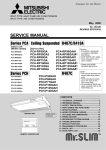
INDOOR UNIT
TIMER
TEMP
12
29
11
28
COOL
10
27
DRY
9
26
FAN
8
25
7
24
6
23
5
22
4
21
3
20
2
19
1
18
TIMER/TEMP.
UP
POWER
HIGH
ON/OFF
MODE
SELECT
LOW
FAN
SPEED
ON
LOUVER
DOWN
AUTO
STOP
START
TIMER
MODE
MITSUBISHI ELECTRIC
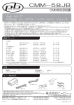
REMOTE CONTROLLER
TECHNICAL CHANGE ·························2
SPECIFICATIONS·································3
DATA ·····················································5
REFRIGERANT SYSTEM DIAGRAM ········7
PARTS LIST··········································8
1
TECHNICAL CHANGE
Differences between the connection with PC-3GJA1
CHANGE POINTS
PC-3GJA1
PC-3GJA2
PU-3VJA2
PU-3VJC
PU-3VJB
PU-3YJA3
PU-3YJC
PU-3YJB
COOLING
CAPACITY
(50Hz)
24600 Btu/h
7200W
25900 Btu/h (PU-3JC)
7600W
25600 Btu/h (PU-3JB)
7500W
TOTAL INPUT (50Hz)
3.30
OUTDOOR UNIT
2.77
2
(PU-3JB)
2
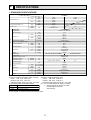
SPECIFICATIONS
1. STANDARD SPECIFICATIONS
Service Ref.
Item
50Hz
Cooling capacity w1
60Hz
Cooling capacity (SSA) w4
60Hz
Total input w2
50Hz
60Hz
Service Ref.
External finish
Fan motor output
50Hz
Indoor unit
60Hz
External static pressure
Operation control &Thermostat
50Hz
60Hz
Unit drain pipe I.D.
Outdoor unit
Dimensions
Weight
Service Ref.
External finish
Refrigerant (R-22) control
Crankcase heater w3
Compressor output
Protection devices
Fan motor output
Airflow
Noise level
Dimensions
H
W
D
kW
CFM
K / min
CFM
Pa(mmAq)
dB
dB
mm(in.)
mm(in.)
mm(in.)
mm(in.)
kg(lbs)
W
kW
50Hz
60Hz
50/60Hz
W
D
H
K / min(CFM)
K / min(CFM)
kW
dB
mm(in.)
mm(in.)
mm(in.)
kg(lbs)
Notes :
w1 Rating conditions (JIS B8616, GB/T 7725-96)
Indoor : D.B. 27°C, W.B. 19°C
Outdoor : D.B. 35°C, W.B. 24°C
Refrigerant piping length (one way) : 5m (16ft)
w2 Total input based on indicated voltage
PC-3GJA2
50Hz
1ph 220V/1ph 220V, 3ph 380V
60Hz
1ph 220V/1ph 220V
7,500
25,600
2.77
PC-3GJA2
Munsell 0.7Y 8.59/0.97
0.07
18-14
635-494
18-14
635-494
0 (Direct blow)
Remote control & Built-in
43-37
43-37
26 (1)
210(8-1/4)
1310(51-9/16)
680(26-3/4)
34(75)
PU-3VJB, PU-3YJB
PU-3VJC, PU-3YJC, PU-3NJA1
Munsell 5Y 7/1
Capillary tube
32/38
(V) 2.2, (Y) 2.4 / (N) 2.2
2.2
w5
0.085
50(1765)
50(1765)
52/53
870(34-1/4)
295+24(11-5/8 add 1)
850(33-7/16)
73(161)
K / min
50/60Hz
50/60Hz
Weight
MODEL
7,600
25,900
7,800
26,600
6,500
22,200
3.30
3.60/4.25 w1/w4
kW
Airflow Hi-Lo
Noise level high-low
PC-3GJA2
W
Btu/h
W
Btu/h
W
Btu/h
w4 Rating conditions (SSA385, 386)
Indoor : D.B. 29°C, W.B. 19°C
Outdoor : D.B. 46°C, W.B. 24°C
Refrigerant piping length (one way) : 5m (16ft)
w5 V, N : Inner thermostat, HP switch, LP switch.
Y : Thermal switch, HP switch, LP switch,
Reversed-phase protector,
Thermal relay
w3 The capacity of crankcase heater (W) based on 220V
3
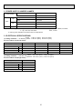
2. POWER SUPPLY & MODEL NAMES
Indoor unit Service Ref.
Power supply
PC-3GJA2
Outdoor unit Service Ref.
1ph.
50Hz
3ph.
60Hz
1ph.
220, 230, 240V
PU-3VJC
220V
PU-3VJB
380/220, 400/230, 415/240V
PU-3YJC
380/220V
PU-3YJB
220V
PU-3NJA1
Notes : 1. Power supply key N... 1ph, 220V,60Hz
V... 1ph, 220, 230, 240V 50Hz
2. Primary power supplies for all indoor units are single-phase.
Y...3ph. 380/220, 400/230, 415/240V,
50Hz, 4 wires
3. ELECTRICAL SPECIFICATIONS
(1). Rating conditions - JIS B 8616 Indoor : D.B. 27°C (80°F), W.B. 19°C (66°F)
Outdoor : D.B. 35°C (95°F), W.B. 24°C (75°F)
PC Series Indoor Unit (Single Phase)
{
Power supply (1 Phase)
Service Ref.
Current
Input
Starting current
V : 220V 50Hz
V : 230V 50Hz
V : 240V 50Hz
N : 220V 60Hz
PC-3GJA2
PC-3GJA2
PC-3GJA2
PC-3GJA2
A
0.51
0.53
0.55
0.70
kW
0.12
0.13
0.15
0.16
A
1.17
1.22
1.27
1.11
PU-3
PU-3
PU-3
PU-3
Outdoor unit
(2). Rating conditions - SSA 385, 386 Indoor : D.B. 29°C (84°F), W.B. 19°C (66°F)
Outdoor : D.B. 46°C (115°F), W.B. 24°C (75°F)
PC Series Indoor Unit (Single Phase)
{
Power supply (1 Phase)
N : 220V 60Hz
Service Ref.
Current
Input
Starting current
Outdoor unit
PC-3GJA2
A
0.70
kW
0.16
A
1.11
PU-3
4
3
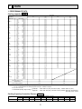
DATA
1. PERFORMANCE DATA
Cooling capacity 50Hz
PC-3GJA2
Service Ref.
PU-3VJB / PU-3YJB
PU-3VJC / PU-3YJC
Temperature
Outdoor D.B.
C.F.
(T.I.)
0.81
0.82
0.83
0.83
0.84
0.86
0.84
0.85
0.86
0.86
0.87
0.89
0.90
0.92
0.93
0.93
0.94
0.96
0.93
0.95
0.96
0.97
0.97
0.99
0.96
0.99
1.00
1.00
1.01
1.04
1.03
1.06
1.07
1.08
1.08
1.11
1.04
1.06
1.08
1.08
1.09
1.12
1.10
1.12
1.14
1.15
1.16
1.20
1.11
1.14
1.15
1.16
1.17
1.21
1.16
1.19
1.21
1.22
1.23
1.28
1.19
1.22
1.24
1.25
1.26
1.31
T.C.
Indoor W.B.
(60.8˚F)
16˚C
(64.4˚F)
18˚C
21˚C
(66.2˚F)
19˚C
(69.8˚F)
(67˚F)
19.4˚C
(68˚F)
20˚C
(71.6˚F)
22˚C
(60.8˚F)
16˚C
(64.4˚F)
18˚C
25˚C
(66.2˚F)
19˚C
(77˚F)
(67˚F)
19.4˚C
(68˚F)
20˚C
(71.6˚F)
22˚C
(60.8˚F)
16˚C
(64.4˚F)
18˚C
30˚C
(66.2˚F)
19˚C
(86˚F)
(67˚F)
19.4˚C
(68˚F)
20˚C
(71.6˚F)
22˚C
(60.8˚F)
16˚C
(64.4˚F)
18˚C
32.2˚C
(66.2˚F)
19˚C
(90˚F)
(67˚F)
19.4˚C
(68˚F)
20˚C
(71.6˚F)
22˚C
(60.8˚F)
16˚C
(64.4˚F)
18˚C
35˚C
(66.2˚F)
19˚C
(95˚F)
(67˚F)
19.4˚C
(68˚F)
20˚C
(71.6˚F)
22˚C
(60.8˚F)
16˚C
(64.4˚F)
18˚C
40˚C
(66.2˚F)
19˚C
(104˚F)
(67˚F)
19.4˚C
(68˚F)
20˚C
(71.6˚F)
22˚C
(60.8˚F)
16˚C
(64.4˚F)
18˚C
40.6˚C
(66.2˚F)
19˚C
(105˚F)
(67˚F)
19.4˚C
(68˚F)
20˚C
(71.6˚F)
22˚C
(60.8˚F)
16˚C
(64.4˚F)
18˚C
45˚C
(66.2˚F)
19˚C
(113˚F)
(67˚F)
19.4˚C
(68˚F)
20˚C
(71.6˚F)
22˚C
(60.8˚F)
16˚C
(64.4˚F)
18˚C
46˚C
(66.2˚F)
19˚C
(115˚F)
(67˚F)
19.4˚C
(68˚F)
20˚C
(71.6˚F)
22˚C
(60.8˚F)
16˚C
(64.4˚F)
18˚C
50˚F
(66.2˚F)
19˚C
(122˚F)
(67˚F)
19.4˚C
(68˚F)
20˚C
(71.6˚F)
22˚C
(60.8˚F)
16˚C
(64.4˚F)
18˚C
52˚C
(66.2˚F)
19˚C
(125.5˚F)
(67˚F)
19.4˚C
(68˚F)
20˚C
(71.6˚F)
22˚C
Evaporator airflow (m3/min)
7.6
8.1
8.4
8.5
8.6
9.1
7.5
7.9
8.2
8.3
8.5
9.0
7.2
7.7
7.9
8.0
8.2
8.7
7.1
7.5
7.8
7.9
8.0
8.5
6.9
7.4
7.6
7.7
7.8
8.4
6.6
7.0
7.3
7.4
7.5
8.0
6.5
7.0
7.2
7.3
7.5
8.0
6.3
6.7
6.9
7.0
7.2
7.7
6.2
6.6
6.9
7.0
7.1
7.6
5.9
6.4
6.6
6.7
6.8
7.3
5.8
6.2
6.4
6.5
6.7
7.2
Bypass factors
S.H.F. at rating conditions
T.C.
C.F.
(T.I.)
0.81
0.82
0.83
0.83
0.84
0.86
0.84
0.85
0.86
0.86
0.87
0.89
0.90
0.92
0.93
0.93
0.94
0.96
0.93
0.95
0.96
0.97
0.97
0.99
0.96
0.99
1.00
1.00
1.01
1.04
1.03
1.06
1.07
1.08
1.08
1.11
1.04
1.06
1.08
1.08
1.09
1.12
1.10
1.12
1.14
1.15
1.16
1.20
1.11
1.14
1.15
1.16
1.17
1.21
7.5
8.0
8.3
8.4
8.5
9.0
7.4
7.8
8.1
8.2
8.4
8.9
7.1
7.6
7.8
7.9
8.1
8.6
7.0
7.4
7.7
7.8
7.9
8.4
6.8
7.3
7.5
7.6
7.7
8.3
6.5
6.9
7.2
7.3
7.4
7.9
6.5
6.9
7.1
7.2
7.4
7.9
6.2
6.6
6.8
6.9
7.1
7.6
6.1
6.5
6.8
6.9
7.0
7.5
18
18
0.08
0.08
0.73
0.73
.
Notes : 1. T.C. : Total capacity ( o 10 W) ... (Btu / h) =. (W) o 3.4, (kcal / h) = (W) o 0.86
C.F. (T.I.) : Correction factors of Total input (Indoor unit input + Outdoor unit input)
2. (°F) = 32 + 9 / 5 (°C)
Lower limit·········Indoor : D.B. 21°C (70°F), W.B. 15.5°C (60°F), Outdoor : D.B. 21°C (70°F)
3. Guaranteed operating range (cooling) Upper limit ·········Indoor : D.B. 35°C (95°F), W.B. 22.5°C (72.5°F), Outdoor : D.B. 52°C (125.5°F) PU-JC
: D.B. 46°C (115°F) PU-JB
3
{
Cooling Capacity Correction Factors 50Hz
Service Ref.
PC-3GJA2
5m (16ft)
1.0
Refrigerant piping length (one way)
10m (33ft) 15m (49ft) 20m (66ft) 25m (82ft) 30m (98ft) 35m (115ft) 40m (131ft) 45m (148ft) 50m (164ft)
0.978
0.962
0.948
0.934
0.921
—
—
—
—
5
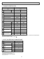
Total
2. STANDARD OPERATION DATA
Service Ref.
PC-3GJA2
MODE
Cooling
Capacity
W
7,600
7,500
Input
kW
3.30
2.77
PC-3GJA2
Electical circuit
Indoor unit service Ref.
Phase, Hz
1, 50
1, 50
Volts
220
220
Amperes
0.51
0.51
PU-3VJC
PU-3VJB
Phase, Hz
1, 50
1, 50
Volts
220
220
Amperes
15.1
12.4
MPa
(kgf/F)
MPa
(kgf/F)
1.96
(20.0)
0.44
(4.5)
1.91
(19.5)
0.46
(4.69)
Discharge temperature
˚C
87.9
84
Condensing temperature
˚C
52.3
50.7
Suction temperature
˚C
3.7
3.8
Ref. pipe length
m
5
5
D.B. ˚C
27
27
W.B. ˚C
19
19
D.B. ˚C
12.2
12.3
D.B. ˚C
35
35
W.B. ˚C
24
24
Outdoor unit service Ref.
Outdoor
side
Indoor side
Refrigerant circuit
Discharge pressure
Suction pressure
Intake air temperature
Discharge air temperature
Intake air temperature
The unit of pressure has been changed to MPa based on SI(International System of unit) in accordance with I.S.O.(International
Organization for Standardization).
The conversion factor is : 1(MPa)=10.2(kgf / F)
60Hz
50Hz
Frequency
3. OUTLET AIR SPEED AND COVERAGE RANGE
Configuration
Ceiling suspended
PC-3GJA2
Service Ref.
3
Airflow
m /min
18
Air speed
m/sec.
3.8
Coverage
m
10.4
range
ft
34.5
Airflow
m /min
18
Air speed
m/sec.
3.8
Coverage
m
10.4
range
ft
34.5
3
The air coverage range is the value up to the position
where the air speed is 0.25 m/sec. when air is blown out
horizontally from the unit at Hi notch position.
The coverage range should be used as a general guideline since it varies according to the size of the room and
furniture inside the room.
6
4
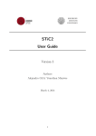
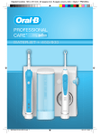
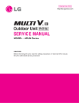
REFRIGERANT SYSTEM DIAGRAM
UNIT : mm(inch)
PC-3GJA2 / PU-3VJC, PU-3YJC
Refrigerant pipe [15.88(5/8")
(with insulator) option
Low pressure
Flexible tube
strainer
switch
PC-3GJA2
Indoor heat
exchanger
Ball
valve
strainer
Charge
pIug
PU-3VJC
PU-3YJC
High pressure
switch
Outdoor heat
exchanger
Check
pIug
Flared
connection
strainer
Flared
connection
Indoor coil
thermistor
RT2
Accumulator
Compressor
Capillary tube
Distributor
with
strainer
(O.D.3.2 oI.D.1.8 o800mm)
o2pcs
Ball valve
(with service port)
D.P.R.
(Discharge pressure regulator)
Refrigerant pipe [ 9.52(3/8")
(with heat insulator) option
flow of refrigerant
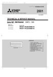
PC-3GJA2 / PU-3VJB, PU-3YJB
Refrigerant pipe [15.88(5/8")
(with insulator) option
Low pressure
Flexible tube
strainer
switch
PC-3GJA2
Indoor heat
exchanger
Ball
valve
strainer
Charge
pIug
PU-3VJB
PU-3YJB
High pressure
switch
Check
pIug
Flared
connection
strainer
Flared
connection
Indoor coil
thermistor
RT2
Accumulator
Compressor
Capillary tube
Distributor
with
strainer
(O.D.3.2 oI.D.1.8 o800mm)
o2pcs
Ball valve
(with service port)
Refrigerant pipe [ 9.52(3/8")
(with heat insulator) option
flow of refrigerant
7
Outdoor heat
exchanger
5
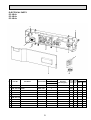
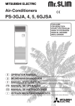
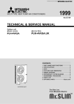
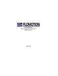
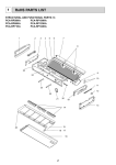
PARTS LIST
FAN PARTS
PC-3GJA
PC-3GJA1
PC-3GJA2
11
18
5
9
1
2
10
4 •14
13
6
8
17
7
15
12
3
16
Q'ty / set
No.
Part No.
Part Name
Specification
PC-3
GJA, GJA1, GJA2
1 T7W 30J 762 FAN MOTOR
1
DC9C4P70MS
Remarks
(Drawing No.)
Wiring RecomDiagram mended
Symbol Q'ty
MF
2 R01 29J 116 FAN JOINT
1
3 R01 29J 100 SHAFT (FAN)
1
4 R01 705 103 SLEEVE BEARING
1
5 R01 29J 130 MOTOR LEG
1
6 R01 29J 114 SIROCCO FAN
2
7 R01 33J 114 SIROCCO FAN
1
8 R01 17J 110 CASING
3
9 R01 17J 202 INDOOR COIL THERMISTOR
1
RT2
10 R01 18J 202 ROOM TEMPERATURE THERMISTOR
1
RT1
11 T7W 33J 480 HEAT EXCHANGER
1
12 R01 29J 529 DRAIN PAN ASSY
1
13 R01 17J 524 DRAIN PLUG
1
14 R01 29J 145 BEARING SUPPORT
1
15 T7W 20J 675 FAN GUARD
1
16 T7W 21J 675 FAN GUARD
2
17 T7W 18J 675 FAN GUARD
1
18 R01 43E 126 PIECE (MOTOR)
1
8
Price
Unit Amount
ELECTRICAL PARTS
PC-3GJA
PC-3GJA1
PC-3GJA2
5
4
3
2
1
6
7
9
8
10
Q'ty / set
No.
Part No.
Part Name
Specification
PC-3
GJA, GJA1, GJA2
1 T7W 27K 310 INDOOR CONTROLLER BOARD
2 T7W 520 239 FUSE
Remarks
(Drawing No.)
Wiring RecomDiagram mended
Symbol Q'ty
1
I.B
1
F1,2<I.B>
3 T7W 23J 260 TRANSFORMER
1
T
4
1
—
250V 6.3A
CONTROL BOX
5 T7W 39J 255 FAN MOTOR CAPACITOR
(BG00N015G12)
1
C
6 T7W 521 716 TERMINAL BLOCK
3P(L,N,;)
1
TB2
7 T7W 512 716 TERMINAL BLOCK
2P(1,2)
1
TB4
8
—
1
BOX COVER
9 T7W 20K 200 REMOTE CONTROLLER BOARD
10 T7W 139 305 REMOTE CONTROLLER CORD
1
1
12m
9
(BG02A804G13)
R.B
Price
Unit Amount
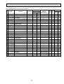
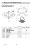
STRUCTURAL PARTS
PC-3GJA
PC-3GJA1
PC-3GJA2
16
11
13
14
12
27
2
18
15
23
5
4
10
24
17
8
1
9
25
6
7
3
10
19
26
22
Part numbers that are circled not shown in the figure.
Q'ty / set
No.
Part No.
Part Name
PC-3
Specification
GJA, GJA1
GJA2
1 R01 17J 661 RIGHT SIDE PANEL
1
1
2 R01 17J 662 LEFT SIDE PANEL
1
1
3 R01 A14 500 L.L. FILTER
2
2
4 R01 29J 676 REAR PANEL
1
1
5 R01 29J 651 FRONT PANEL
1
1
6 R01 17J 691 GRILLE ASSY
2
2
7 R01 29J 669 UNDER PANEL
1
1
8 R01 17J 061 GRILLE HINGE
4
4
9 R01 17J 054 GRILLE CATCH
4
4
10 R01 17J 067 RIGHT SIDE BOX
1
1
11 R01 17J 068 LEFT SIDE BOX
1
1
12 R01 17J 085 GUIDE VANE ASSY-6R.
1
1
13 R01 18J 086 GUIDE VANE ASSY-6L.
1
1
14 R01 29J 087 GUIDE VANE ASSY-6C.
1
1
15 R01 29J 002 AUTO VANE
1
1
16 R01 29J 223 VANE MOTOR
1
1
17 R01 17J 808 RIGHT LEG
1
1
18 R01 17J 809 LEFT LEG
1
1
19 R01 17J 070 WIRELESS BOARD CASE
1
1
20 R01 17J 523 JOINT SOCKET
1
1
21 R01 17J 072 DRAIN HOSE COVER
1
1
22 R01 18J 665 SIDE PLATE-R.
1
1
23 R01 18J 666 SIDE PLATE-L.
1
1
24 R01 17J 668 SERVICE PANEL
1
1
Remarks
(Drawing No.)
MV
25
—
BEAM(GA)
2
2
(BG17H464H08)
26
—
REAR SUPPORT
1
1
(BG02H454H04)
27
—
VANE SUPPORT
2
2
(BG02R321G06)
11
Wiring RecomDiagram mended
Symbol Q'ty
Price
Unit Amount
HEAD OFFICE MITSUBISHI DENKI BLDG.MARUNOUCHI TOKYO100-8310 TELEX J24532 CABLE MELCO TOKYO
cCopyright 1999 MITSUBISHI ELECTRIC ENGINEERING CO., LTD.
Issued in Nov. 1999. No. OC208 1572
Printed in Japan
New publication, effective Nov. 1999
Specifications subject to change without notice