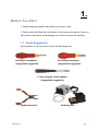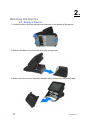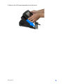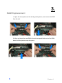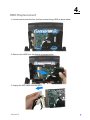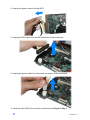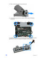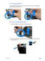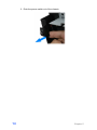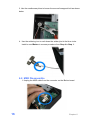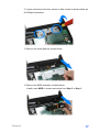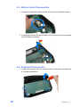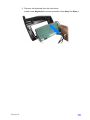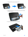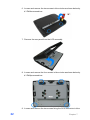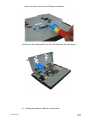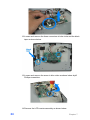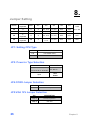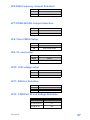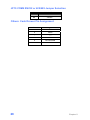
1
Service Manual
POS60-5B-C1G
POS60-2B-C1G
POS60-8B-C1G
Copyrights
©2009. All rights reserved. The information in this
document is subject to change without prior notice in
order to improve reliability, design and function and does
not represent a commitment on the part of the
manufacturer.
This document contains proprietary information
protected by copyright. All rights are reserved. No
part of this manual may be reproduced by any
mechanical, electronic, or other means in any form
without prior written permission of the manufacturer.
All trademarks are property of their respective
owners
Liability Disclaimer
In no event will the manufacturer be liable for direct,
indirect, special, incidental, or consequential
damages arising out of the use or inability to use the
product or documentation, even if advised of the
possibility of such damages.
The information in this document is subject to
change without notice
Copyrights
i
Contents
Copyrights .................................................................................................i
Liability Disclaimer ...................................................................................i
Contents....................................................................................................ii
Before You Start .......................................................................................1
Opening the Device..................................................................................2
2.1. Remove Covers ............................................................................................ 2
2.2. Remove LCD Panel Assembly..................................................................... 4
RAM Replacement....................................................................................6
HDD Replacement ....................................................................................7
Mainboard and Component Replacement .............................................9
5.1. How to dissemble the mainboard from the device.................................... 9
5.2. Unplug SCSI Cable..................................................................................... 12
5.3. Unplug COM Port ....................................................................................... 13
5.4. Power Switch Dissemble ........................................................................... 13
Front Cover Assembly ...........................................................................15
6.1. iButton Module ........................................................................................... 15
6.2. MSR Disassemble ...................................................................................... 16
6.3. iButton Board Disassemble ...................................................................... 18
6.4. Keyboard Disassemble.............................................................................. 18
LCD Panel Assembly .............................................................................20
Jumper Setting .......................................................................................26
ii
Contents
1.
Before You Start
1. Please unplug the power cable before you start to work.
2. Please read and follow the instructions in this document carefully. Failure to
follow these instructions could damage your device and void the warranty.
1.1. Tools Suggested
All procedures in this document require the following tools:
#0 Phillips screwdriver
(magnetized suggested)
#1 Phillips screwdriver
(magnetized suggested)
1.5 mm hexagon socket spanner
(magnetized suggested)
needlenose pliers
Chapter 1
Soldering iron
1
2.
Opening the Device
2.1. Remove Covers
1. Loosen the three tool-free screws anticlockwise on the bottom of the device.
2. Remove the back cover from the device by pulling back.
3. Remove the front covert assembly, beware that the connected keyboard cable.
2
Chapter 2
3. Unplug the keyboard cable; put the front covert assembly in the proper place.
4. Loosen and remove two screws on the middle cover by #1 Phillips screwdriver.
5. Pull the middle cover in the direction as shown below.
Chapter 2
3
6. Bend the middle cover softly in the direction as shown below to remove it from the
device.
7. Unplug the SCSI connector and the phone jack of the speaker.
2.2. Remove LCD Panel Assembly
1. Loosen and remove four screws by #1 Phillips screwdriver as shown below
4
Chapter 2
2. Remove the LCD panel assembly from the device.
Chapter 2
5
3.
RAM Replacement
1. Open the tow ejectors on the slot by pushing them, and remove the RAM
from the slot.
2. Align and insert the new RAM in the slot and push both ends of the RAM
down until the ejectors snap into place.
6
Chapter 4
4.
HDD Replacement
1. Loosen and remove the four tool-free screws fixing HDD as show below.
2. Remove the HDD from the device as shown below.
3. Unplug the IDE cable from the HDD.
Chapter 5
7
4. Unplug the power cable from the HDD.
5. Unplug the IDE cable from the IDE connector of the mainboard.
6. Unplug the power cable from the power connector of the mainboard.
5. Install the new HDD in the reverse procedure from Step 6 to Step 1.
8
Chapter 5
5.
Mainboard and Component Replacement
5.1. How to dissemble the mainboard from the device
1. Follow procedures described in previous sections to remove covers and
HDD.
2. Loosen and remove the two tool-free screws on the I/O panel as shown
below.
3. Unplug the power switch cable from the mainboard.
Chapter 5
9
4. Draw out the base chassis from the device.
5. Loosen and remove the four screws in blue circle #1 Phillips by
screwdriver.
5. Loosen and remove the six hexagonal bolts fixing COM ports and the
parallel port in the blue rectangle by hexagon socket spanner.
10
Chapter 5
6. Remove the O-ring fixing the audio cable.
7. Loosen and remove the two screws fixing SCSI connector in the blue
circle by #0 Phillips screwdriver.
8. Remove the mainboard from the base chassis.
Chapter 5
11
5.2. Unplug SCSI Cable
1. Unplug 8-pin female connector of SCSI cable from the male connector on
the mainboard behind the USB port.
2. Unplug 13-pin female connector of SCSI cable from the male connector on
the mainboard next to the HDD power connector.
3. Unplug 15-pin female connector of SCSI cable from the male connector on
the mainboard next to the IDE socket.
12
Chapter 5
5.3. Unplug COM Port
1. Unplug two COM port cables from the male connector on the mainboard
behind the purple parallel port.
5.4. Power Switch Dissemble
1. Unplug the power switch cable from the mainboard.
2. Press and holding the clip of the power switch, and push in the direction
as shown below.
Chapter 5
13
3. Push the power switch out of the chassis.
14
Chapter 5
6.
Front Cover Assembly
6.1. iButton Module
1. Unplug the iButton cable from the iButton board.
2. Use the needlenose pliers to loosen the first hexagonal bolt as shown
below.
Chapter 6
15
3. Use the needlenose pliers to loosen the second hexagonal bolt as shown
below.
4. Use the soldering iron to melt down the solder joint in the blue circle.
Install a new iButton in reverse procedure from Step 4 to Step 1.
6.2. MSR Disassemble
1. Unplug the MSR cable from the connector on the iButton board.
16
Chapter 6
2. Loosen and remove the four screws in blue circles as shown below by
#1 Phillips screwdriver.
3. Remove the metal plate as shown below.
3. Remove the MSR assembly as show below.
Install a new MSR in reverse procedure from Step 3 to Step 1.
Chapter 6
17
6.3. iButton Board Disassemble
1. Unplug the keyboard cable from the connector on the iButton board.
2. Loosen and remove the two screws in blue circles by as shown below
by #1 Phillips screwdriver.
6.4. Keyboard Disassemble
1. Loosen and remove the four screws in blue circles as shown below by
#1 Phillips screwdriver.
18
Chapter 6
2. Remove the keyboard from the front cover.
Install a new Keyboard in reverse procedure from Step 2 to Step 1.
Chapter 6
19
7.
LCD Panel Assembly
1. Loosen and remove the two screws in blue circles as shown below by
#1 Phillips screwdriver.
2. Remove the plastic panel.
20
Chapter 7
3. Unplug the SCSI connector and the phone jack.
4. Loosen and remove the four screws in blue circles as shown below by
#1 Phillips screwdriver.
5. Remove the metal stand from the LCD assembly.
Chapter 7
21
6. Loosen and remove the two screws in blue circles as shown below by
#1 Phillips screwdriver.
7. Remove the rear panel from the LCD assembly.
8. Loosen and remove the four screws in blue circles as shown below by
#1 Phillips screwdriver.
9. Loosen and remove the two screws fixing the SCSI connector in blue
22
Chapter 7
circles as shown below by #1 Phillips screwdriver.
10. Remove the metal panel from the LCD assembly as show below.
11. Unplug the speaker cable as shown below
Chapter 7
23
12. Loosen and remove the three connectors in blue circle and the black
tape as shone below.
13. Loosen and remove the screw in blue circle as shone below by #1
Phillips screwdriver.
14. Remove the LCD inverter assembly as shown below.
24
Chapter 7
15. Remove the LCD panel as shown below.
Install the new LCD and re-assemble the LCD assembly in the reverse
procedure from Step 15 to Step 1.
Chapter 7
25
8.
Jumper Setting
I-Button
P.
Keyboard
MSR
JP1
JP2
JP3
JP4
JP5
KB
X
X
X
3-4, 9-10
1-2, 5-6
OFF
OFF
RS232
X
X
1-8
1-2, 7-8
OFF
ON
OFF
KB
P.
Keyboard
X
X
3-4, 9-10
1-2, 5-6
OFF
OFF
OFF
KB
P.
Keyboard
KB
X
5-6,
11-12
1-2, 5-6
OFF
OFF
OFF
P.KB
JP1, JP2
JP1: Setting CPU Type
JP1
DESCRIPTION
1-2
P4/ Celeron 2.0G
2-3
Mobile Celeron 1.2G
JP2: Power-in Type Selection
JP2
DESCRIPTION
1-2,3-4,5-6,7-8,9-10,11-12,
13-14,15-16,17-18,19-20
12V Jack-In
ATX-
Open
Power
JP4:COM3 Jumper Selection
JP4
DESCRIPTION
1-3,2-4
Normal Operation
JP5:VGA 12V Jumper Selection
26
JP5
DESCRIPTION
1-3,2-4
Normal Operation
1-2,3-4
Use 12V
Chapter 8
JP6:FSB Frequency Jumper Selection
JP6
DESCRIPTION
1-2,3-4
FSB 400
Open
FSB 533
JP7:COM4 422/485 Jumper Selection
JP7
DESCRIPTION
1-2
422
2-3
485
JP8: Clear CMOS Setup
JP8
DESCRIPTION
1-2
Normal Operation
2-3
Clear CMOS Setup
JP9
DESCRIPTION
Close
Master
Open
Slave
JP9: CF card setup
JP10: LCD voltage setup
JP10
DESCRIPTION
1-2
3.3V
3-4
5V
JP11: K/B Use Selection
JP11
DESCRIPTION
2-3,4-5
Normal Operation
Open
Use for JP11
JP12: COM Port RI and Voltage Selection
JP12
DESCRIPTION
5-6,11-12,17-18
Use for RI
3-4,9-10,15-16
5V
1-2,7-8,13-14
Chapter 8
12V
27
JP13:COM4 RS232 or 422/485 Jumper Selection
JP13
DESCRIPTION
1-2
RS232
2-3
422/485
Others: Cash Drawer Pin Assignment
28
Pin
Assignment
1
GND
2
DOUT
3
DIN
4
12V
5
No Connected
6
GND
Chapter 8