1
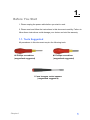
Service Manual
EZPPC-70D-5B-C15G
EZPPC-70D-5B-C1G
EZPOS-70D-5B-C15G
EZPOS-70D-5B-C1G
Copyrights
©2009 All rights reserved. The information in this
document is subject to change without prior notice in
order to improve reliability, design and function and does
not represent a commitment on the part of the
manufacturer.
This document contains proprietary information
protected by copyright. All rights are reserved. No
part of this manual may be reproduced by any
mechanical, electronic, or other means in any form
without prior written permission of the manufacturer.
All trademarks are property of their respective
owners
Liability Disclaimer
In no event will the manufacturer be liable for direct,
indirect, special, incidental, or consequential
damages arising out of the use or inability to use the
product or documentation, even if advised of the
possibility of such damages.
The information in this document is subject to
change without notice
Copyrights
i
Contents
Copyrights .................................................................................................i
Liability Disclaimer ...................................................................................i
Contents....................................................................................................ii
1. Before You Start ...................................................................................1
2. Opening the Device..............................................................................2
3. Connect Battery Pack ..........................................................................3
4. RAM Replacement................................................................................5
5. Battery Replacement ...........................................................................6
6. LED indicator Replacement ................................................................7
7. Speaker Assembly Replacement ........................................................8
8. HDD Replacement ..............................................................................10
9. LCD Inverter Replacement ................................................................12
9.1. Disconnect Inverter Cable ......................................................................... 12
9.2. Remove the LCD Inverter .......................................................................... 13
10. Touch Panel Control Board Replacement......................................15
10.1. Disconnect Touch Panel Control Board Cable ...................................... 15
10.2. Remove the Touch Panel Control Board................................................ 16
11. Power Switch Replacement.............................................................17
12. COM Cable Replacement.................................................................18
13. Mainboard Replacement..................................................................19
14. I/O Panel Replacement ....................................................................20
15. LCD Panel Replacement..................................................................22
16. BIOS setup........................................................................................24
16.1. System Time and System Date Adjustment........................................... 25
16.2. Serial ports Configuration ....................................................................... 25
16.3. Boot Device Configuration ...................................................................... 26
16.4. Save Configuration Changes and Exit ................................................... 26
ii
Contents
1.
1. Before You Start
1. Please unplug the power cable before you start to work.
2. Please read and follow the instructions in this document carefully. Failure to
follow these instructions could damage your device and void the warranty.
1.1. Tools Suggested
All procedures in this document require the following tools:
#0 Phillips screwdriver
(magnetized suggested)
#1 Phillips screwdriver
(magnetized suggested)
1.5 mm hexagon socket spanner
(magnetized suggested)
Chapter 1
1
2.
2. Opening the Device
1. Un-tighten two screws on the back panel anticlockwise.
2. Open the back panel.
3. The layout of the internal.
2
Chapter 2
3.
3. Connect Battery Pack
Before power-on the device, please connect the battery to the mainboard:
1. Un-tighten two screws on the back panel anticlockwise.
2. Open the back panel.
3. For the location of the battery pack and the 10-1 pin male power connector,
please refer the picture shown below.
Chapter 3
3
4. Plug the power cable to the 9-pin power connector in the correct orient.
5. Close the back panel and tighten two screws on the back panel.
4
Chapter 3
4.
4. RAM Replacement
1. Open the tow ejectors on the slot by pushing them, and remove the RAM
from the slot.
4. Remove the old RAM and install a new one.
5. Align and insert the new RAM in the slot and push both ends of the RAM
down until the ejectors snap into place.
Chapter 3
5
5.
5. Battery Replacement
1. Unplug the connector of the battery from the mainboard.
2. Loosen the two screws by #1 Phillips screwdriver as shown below and remove
the battery..
3. Install a new battery in the reverse procedure
Note: The battery cable must be connected in the correct orient.
6
Chapter 5
6.
6. LED indicator Replacement
1.
Unplug the connector of the LED indicator assembly from the mainboard.
2. Loosen the two screws by #1 Phillips screwdriver as shown below and remove
LED indicator assembly.
3. Install a new LED indicator assembly in the reverse procedure.
Chapter 6
7
7.
7. Speaker Assembly Replacement
1. Disconnect the connector of the speaker assembly from the mainboard as shown
below.
2. Loosen the four screws by #1 Phillips screwdriver as shown below and remove the
HDD from the device.
8
Chapter 7
3. Remove the speaker assembly from the device.
4. Install a new LED indicator assembly in the reverse procedure.
Chapter 7
9
8.
8. HDD Replacement
1. Unplug one connector of the SATA cable from the mainboard.
2. Unplug one connector of the HDD power cable from the mainboard.
3. Loosen the four screws by #1 Phillips screwdriver as shown below and remove the
HDD from the device.
10
Chapter 8
4. Unplug the SATA cable and power cable from the HDD.
4. Loosen the four screws by #1 Phillips screwdriver and remove the HDDas shown
below.
5. Install the new HDD in the reverse procedure from Step 5 to Step 1.
Chapter 8
11
9.
9. LCD Inverter Replacement
9.1. Disconnect Inverter Cable
1. Disconnect the inverter cable from the mainboard.
2. Remover the black tap as shown below.
12
Chapter 9
3. Disconnect the inverter cable from the LCD inverter as shown below.
9.2. Remove the LCD Inverter
1. Disconnect two connecters form the LCD inverter as shown below.
2. Loosen the three screws by #0 Phillips screwdriver as shown below.
Chapter 9
13
3. Remove the LCD inverter from the device as shown below.
4. Install the new LCD inverter in the reverse procedure from Step 5 to
Step 1.
14
Chapter 9
10.
10. Touch Panel Control Board Replacement
10.1. Disconnect Touch Panel Control Board Cable
1. Disconnect Touch Panel Control Board Cable from the mainboard as
shown below.
2. Remover the black tap as shown below.
3. Disconnect two connecters form the touch panel control board as shown
below.
Chapter 10
15
10.2. Remove the Touch Panel Control Board
1. Loosen the two screws by #0 Phillips screwdriver as shown below.
2. Remove the touch panel control board from the device as shown below.
3. Install the new touch panel control board in the reverse procedure from
Step 3 to Step 1of 9.2 and 9.1.
16
Chapter 10
11.
11. Power Switch Replacement
1. Disconnect the power switch cable from the mainboard.
2. Remove the power switch from the device.
3. Install the new touch panel control board in the reverse procedure from Step 2 to
Step 1.
Note: The power switch cable must be connected to the correct pin.
Chapter 7
17
12.
12. COM Cable Replacement
1. Disconnect the two COM cables from the mainboard.
2. Disconnect the two COM cables from the I/O panel.
3. Install the new COM cables in the reverse procedure from Step 2 to Step 1.
18
Chapter 11
13.
13. Mainboard Replacement
1. Loosen the five screws by #0 Phillips screwdriver as shown below.
2. Remove the mainboard from the device as shown below.
3. Install the new mainboard in the reverse procedure from Step 2 to Step 1.
Chapter 14
19
14.
14. I/O Panel Replacement
1. Remove the two screws by #1 Phillips screwdriver as shown below.
2. Remove the two screws by #1 Phillips screwdriver as shown below.
3. Remove the I/O panel from the device.
20
Chapter 14
4. Loosen the four screws by 1.5 mm hexagon socket spanner to remove the COM port
assembly as shown below.
5. Install the new COM port assembly to the new I/O panel and install it to the device in
the reverse procedure from Step 3 to Step 1.
Chapter 14
21
15.
15. LCD Panel Replacement
1. Loosen the eight screws in blue circle as shown below by #1 Phillips screwdriver.
2. Remove the LCD panel assembly from the device as shown below.
22
Chapter 15
3. Loosen the four screws on the two sides of the LCD panel assembly #1 Phillips
screwdriver as shown below.
4. Remove the two metal racks from the LCD panel.
5. Install a new LCD panel to the device in the reverse procedure from Step 4 to Step 1.
Chapter 15
23
16.
16. BIOS setup
1. Press and hold the power switch until the power indicator on the front panel glow green.
2. Before Windows launch, Press the “Delete” key to enter he BIOS.
24
Chapter 16
16.1. System Time and System Date Adjustment
1. Under the Main tab, press the four arrow keys to high light the System Time and
System Date to configure.
16.2. Serial ports Configuration
1. Press “→” key to switch to “Advanced” tab and press “↓” to highlight “Super IO
Configuration”, and then press the Enter key to switch to the Configure Super IO
Chipsets screen.
2. Pressing arrows keys to set every serial port power source, and then press F10 to save
your configuration and exit.
Chapter 16
25
16.3. Boot Device Configuration
1. Press “→” key to switch to “Boot” tab and press “↓” to configure the boot device
16.4. Save Configuration Changes and Exit
Press F10 key and highlight the [OK] on the message box by pressing a arrow key and
press the Enter Key.
26
Chapter 16