1
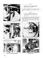
RV Generator Sets
Models:
3.5CM21
3.5CM61
3.5CFM21
3.5CFM61
4.5CM21
4.5CM61
4.5CFM21
4.5CFM61
5.5CM21
5.5CM61
5.5CFM21
5.5CFM61
7CM21
7CM61
KOHLER.
POWERSYSTEMS
TP-5014 11/87
TABLE
Safety Precautions..
SECTION
l-l.
l-2.
l-3.
1-4.
1-5.
1-6.
l-7.
OF CONTENTS
Page
....................
1. INTRODUCTION
AND SPECIFICATIONS
Introduction
.......................
Model 3.5CM21-RV
..................
.................
Model 4.5CM21-RV
.................
Model 5.5CM21-RV
Model 7CM21-RV.
..................
Oil Specifications
....................
Fuel Specifications
..................
1-I
l-1
.1-l
J-1
.1-l
SECTION 5. DECISION
5-I.
5-2.
5-3.
5-4.
5-5.
.............................
Description
..................
Sequence of Operation
Fuses.....................................5Circuit Boards ...........................
Circuit Board Foil Repair .................
.........................
SECTION
3-1.
3-2.
3. SCHEDULED
3
.5-3
.5-3
l-4
SECTION 2. OPERATION
General..
.....................
Prestart Checklist ....................
Operation
.5-l
.5-l
.I-4
SECTION
2-1.
2-2.
2-3.
MAKER CONTROLLER
..==2
-1
2-l
2-l
MAINTENANCE
6-l.
6-2.
6-3.
6-4.
6-5.
6-6.
6-7.
6-8.
6-9.
6-10.
6-I 1.
6. GENERATOR
General. . . . . . . . . . . . . . . . . . . . . . . . . . .6-l
Troubleshooting
....................
.6-l
Generator Disassembly
...............
.6-Z
Build-Up Circuit ....................
.6-5
.6-5
Brushes. .........................
.6-5
Collector Rings ....................
Exciter Voltage Regulator
.............
.6-6
Stator. ..........................
.6-8
.6-8
Rotor ...........................
Interlock Circuit Board ...............
.6-9
Generator Reassembly ................
.6-IO
General . . . . . . . . . . . . . . . . . . . . . . . . . . .3-l
Scheduled Maintenance . . . . . . . . . . . . . . . .3-l
SECTION 7. CHOKE, SHUTDOWN
CONTROL, AND GOVERNOR
SECTION 4. TROUBLESHOOTING
7-1.
7.2
4-l.
4-2.
4-3.
General . . . . . . . . . . . . . . . . . . . . . . . . . . .4-l
RV Systems Check . . . . . . . . . . . . . . . . . . .4-l
Troubleshooting
. . . . . . . . . . . . . . . . . . . . .a-3
7.3
7.4
7.5
7.6
Choke Testing and Adjustments
(3.5kW, 4.5kW) . . . . . . . . . . . . . . . . . . . . . . . . . . . . . . . .
Choke Testing and Adjustments
(5.5kW, 7kW). . . . . . . . . . . . . . . . . . . . . . . . . . . . . . . . . .
Positive Shutdown Control . . . . . . . . . . . . . . . . . . .
Governor (3.5kW, 4.5kW) . . . . . . . . . . . . . . . . . . . . .
Governor Hunting Checks (4.5kW Only) . . . . .
Governor (5.5kW, 7kW) . . . . . . . . . . . . . . . . . . . . . . .
SECTION
8. WIRING
DIAGRAMS
7-I
7-3
7-3
7-4
7-5
7-5
Safety Precautions
A Generator Set, like any other eiectro-mechanical
device
can pose potential dangers to life and limb if improperly
maintained or imprudently
operated. The best safeguards
against accident are to be ever mindful of the potential
dangers and to always use good common sense. In the
interest of safety, some general precautions
relating to
operating
of a Generator Set are presented below. Keep
these in mind.
A WARNING
LETHAL EXHAUST GAS! An engine discharges
deadly
carbon monoxide as part of the exhaust when operating.
Carbon monoxide is particularly
dangerous in that it is an
odorless,
tasteless, and nonirritating
gas, but be ever
mindful that it can cause death if inhaled for even a short
period of time. Have only qualified specialists install and
replace exhaust system components
and have the system
inspected frequently.
Be careful when parking your coach
to avoid obstructing
the exhaust outlet. The exhaust
gasses must discharge freely, otherwise carbon monoxide
may deflect under and into the vehicle or enter through
open doors, windows, or vents. Also make sure that your
exhaust cannot be discharged
toward neighboring
RV’s,
campers, or any occupied building. Be especially watchful
for exhaust accumulation
under calm, windless conditions.
A WARNING
ELECTRICAL SHOCK! Battery can cause electrical burns
and shocks. Exercise reasonable care when working near
the battery to avoid electrical connections
through tools.
Remove wristwatch,
rings, and any other jewelry.
A
WARNING
HIGH VOLTAGE! Remember that the function of a generator set is to produce electricity
and that wherever electricity is present, there is the potential danger of electrocution. Take the same precautions
with electrical appliances
in your coach that you would observe in your home. Keep
away from electrical
circuits and wiring while the set is
running and have electrical
service performed
only by
qualified
electricians.
Make sure unqualified
persons,
especially children, cannot gain access to your set - keep
the compartment
door locked or securely latched at all
times. Be sure that generator is properly grounded. Never
touch electrical leads or appliances with wet hands, when
standing
in water, or on wet ground as the chance of
electrocution
is especially
prevalent
under such conditions.
A WARNING
UNIT STARTS WITHOUT NOTICE! To prevent accidental
starting on units with a remote start/stop switch, always
disconnect
battery (remove negative lead first and reconnect it last) to disable generator set before working on any
equipment connected to generator.
A WARNING
DANGEROUS ACID! Avoid contact with battery electrolyte. It contains acid which can eat holes in clothing, burn
skin, and cause permanent damage to eyes. Always wear
splash-proof
safety goggles when working
around the
battery. If battery electrolyte
is splashed in the eyes or on
skin, immediately
flush the affected area for 15 minutes
with large quantities
of clean water. in the case of eye
contact, seek immediate medical aid. Never add acid to a
battery once the battery has been placed in service. Doing
so may result in dangerous spattering of electrolyte.
A WARNING
EXPLOSIVE BATTERY GASES! The gases generated by a
battery being charged are highly explosive. Do not smoke
or permit flame or spark to occur near a battery at any
time, particularly
when it is being charged. Avoid contacting terminals
with tools, etc., to prevent burns and to
prevent sparks that could cause an explosion.
Remove
wristwatch,
rings, and any other jewelry before handling
battery. Any compartment
containing
batteries should be
well ventilated to prevent accumulation
of explosive gases.
To avoid sparks, do not disturb battery charger connections while battery is being charged and always turn
charger off before disconnecting
battery connections.
Turn automotive
test equipment
off when connecting
or
removing battery clips. When removing or reconnecting
battery cables, make sure ignition switch and all accessories are turned off.
A WARNING
EXCESSIVE
NOISE! Never operate
without
adequate
muffler or with faulty exhaust system - exposure
to
excessive noise is not only tiring but can lead to impairment of hearing.
A WARNING
HOT PIPING! An engine gets hot while running and
exhaust system components
get extremely
hot. Do not
work on generator set until unit is allowed to cool.
A WARNING
DANGEROUS FUELS! Use extreme caution when handling, storing,
and using fuels - all fuels are highly
explosive in a vapor state. Store fuel in a well-ventilated
areaawayfrom
spark producing equipment and out of the
reach of children.
Never add fuel to the tank while the
engine is running to prevent spilled fuel from igniting on
contact with hot parts or from ignition spark. Keep fuel
lines and connections
tight and in good condition -don’t
replace flexible fuel lines with rigid lines. Flexible sections
are used to avoid breakage due to vibration. Should any
fuel leakage, fuel accumulation,
or electrical
sparks be
noted, DO NOT OPERATE GENERATOR SET. Have sys-
terns repaired by qualified
specialists
before resuming
generator
operation.
Additional
precautions
should be
taken when using the following fuels:
Gasoline-Store
gasoline only in approved red containers
clearly marked GASOLINE.
Don’t store gasoline in any
occupied building.
Propane (LP)-Adequate
ventilation
is mandatory.
Propane is heavier than air; install gas detectors low in room.
Inspect detectors often.
A WARNING
UNINTENTIONAL
STARTING!
To prevent accidental
starting when checking choke operation,
remove spark
plug lead(s) at spark plug(s).
A WARNING
FLASH FIRE! A sudden flash fire can cause serious burns.
To avoid the possibility
of a flash fire, do not smoke or
permit flame or spark to occur near carburetor,
fuel line,
fuel filter, fuel pump, or other potential sources of spilled
fuel or fuel vapors.
A
A WARNING
BACKFIRE! A sudden backfire can cause serious burns.
Keep hands and face away from the carburetor when the
air cleaner is removed.
A WARNING
FIRE HAZARD! Keep the compartment
and generator set
clean and free of debris to minimize chances of fire. Also
remember
that hot exhaust gases and exhaust system
parts could start grass fires. Keep away from hot engine
and generator parts to avoid burning yourself.
A WARNING
MOVING PARTS! Do not open generator set compartment
door when unit is running, except for servicing by qualified specialists.
Replace guards, covers, and screens (if
used) before operating generator set.
A WARNING
HIGH VOLTAGE! When the power cord is plugged in
during voltage regulator test, the AC pins become “hot”
and there is danger of electrocution.
WARNING
ELECTROCUTION!
Your RV generator set must not be
used to “backfeed”
by connecting
it to building/campground electrical
circuits. Doing so can cause serious
injury or death to utility personnel
working
on utility
transmission
lines and may also seriously injure persons in
your household. Unauthorized connection may be unlawful
in some states and/or localities. A transfer switch must be
installed in the RV to prevent interconnection
of generator
and outside source of power.
A WARNING
EXPLOSION! Use generator
installations
only.
sets specified
for RV use in RV
SECTION
INTRODUCTION
l-l.
AND
1
SPECIFICATIONS
INTRODUCTION
l-3.
This manual covers operation,
scheduled maintenance
troubleshooting
and corrective maintenance for Kohler generator sets designed and built for recreational vehicles. The
four standard models are the 3.5CM21-RV, 4.5CM2LRV,
5.5CM21-RV and 7CM21-RV. These models are referred to
by their kilowatt output, 3.5KW, 4.5KW, 5.5KW and 7KW.
Differences between models are noted throughout the manual. All models feature Kohler designed and built 4-cycle
air-cooled gasoline engines, rotating field generators and
Decision Maker Controllers. See Table l-l for specifications
and model variations, Table l-2 for dimensions and weight,
and Table l-3 for enigne specifications. Refer to the wiring
diagrams in the back of the manual.
l-2.
This 4500 watt generator set is powered by a single cylinder
Kohler Model K341QS engine. The set produces 120 volt,
37.7 amp alternating current. It has a rotor with four magnetic poles and operates at 1800 R.P.M., producing 60
hertz. A 40 amp line circuit breaker protects generator
against damage due to overload. See Figure 1-2 for major
components.
1-4.
This 3500 watt generator set is powered by a single cylinder
model K181 QS engine. The set produces 120 volt, 29 amp
alternating current. It has a rotor with two magnetic poles
and operates at 3600 R.P.M., producing 60 hertz or 3000
R.P.M., producing 50 hertz, 13 amp current. A 30 amp circuit breaker protects the set from overload damage. Due to
its compact size and lightweight, it is installed in RV’s with
limited
suspension support and compartment
space. See
Figure l-l for major components.
Volts
Amps Per
Terminal
MODEL 5.5CM21-RV
The 5500 watt generator set is powered by a two cylinder
Kohler Model K582QS engine. The set produces 120 volt,
46 amp alternating current. It has a rotor with four magnetic poles and operates at 1800 R.P.M., producing 60 hertz.
A 50 amp circuit breaker (on most models) protects against
damage due to overload. See Figure 1-3 for major components.
MODEL 3.5CM21-RV
Model
MODEL 4.5CM21-RV
1-5. MODEL 7CM21-RV
The 7000 watt generator set is powered by a two cylinder
Kohler Model K582QS engine. The set produces 120 volt,
58 amp alternating current. It has a rotor with four magnetic poles and operates at 1800 R.P.M., producing 60 hertz.
A 60 amp circuit breaker (on most models) protects against
damage due to overload. See Figure l-3 for major components.
Watts
Freq. (HZ)
Wires
Phase
3.5CM21 -RV
120
29
3500
60
3600
2
1
3.5CM61 -RV
120/240
14.5
3500
60
3600
3
1
120
26.6
3200
50
3000
2
1
1201240
13.3
3200
50
3000
3
1
4.5CM21 -RV
120
37.5
4500
60
1800
2
1
4.5CM61 -RV
1201240
18.8
4500
60
1800
3
1
3.5CFM21-RV
3.5CFM61 -RV
4.5CFM21-RV
120
30
3600
50
1500
2
1
4.5CFM61-RV
1201240
15
3600
50
1500
3
1
5.5CM21
120
46
5500
60
1800
2
1
5.5CM61
1201240
23
5500
60
1800
3
1
1
5.5CFM21
120
5.5CFM61
1201240
37.5
4500
50
1500
2
18.8
4500
50
1500
3
1
7CM21
120
58
7000
60
1800
2
1
7CM61
1201240
26
7000
60
1800
3
1
l
Table l-l.
I
Specification
3.5 Model
Generator
I
Specifications
4.5 Model
I
7.0 Model
5.5 Model
146 lb.
237 lb.*
315 lb.
350 lb.
22”
23-l 3/l 6”
26”
27-112”
Width - Overall
l3-314”
18-3 /I 6”
21-l/2”
21-l/2”
Height - Overall
15-314”
19-‘l/16”
20-318”
20-318”
Weight (approximate)
Length - Overall
Table 1-2. Dimensions and Weight
*Earlier
Models 250 lb.
I-1
l
Specifications
\
Fuel Inlet Connection Size
Battery Voltage
3.5 Model
l/4”
4.5 Model
I.D.
l/4”
I.D.
5.5 Model
l/4”
I.D.
7.0 Model
I.D.
l/4”
12v
12v
12v
12v
Battery Amp Hr.
32 to 45
32 to 45
32 to 45
32 to 45
Battery Ground
Negative
Negative
Negative
Negative
Battery Cranking Current
40 amps
76 amps
98 amps
98 amps
Battery Charging Current
15 amps
7 amps
7 amps
Engine Model
K181QS
Breaker Point Gap
0.020”
Number of Cylinders
Cylinder Block
K34 1OS
0.016” to 0.020”
7 amps
K582QS
K582QS
0.020”
0.020”
1
1
2
2
Cast Iron
Cast Iron
Cast Iron
Cast Iron
8
9.2
13.8
13.8
Rated Horsepower
RPM
3600
1800
1800
1800
Bore
2.94,’
3.50”
3.50”
3.50”
Stroke
2.75”
3.25”
3”
3”
Forged Steel
Valve Material
Intake
Forged Steel
Forged Steel
Forged Steel
Stellite
Stel I ite
Stellite
Stellite
Valve Rotators
Exhaust Valves
Exhaust Valves
Exhaust Valves
Exhaust Valves
Cylinder Head
Aluminum Alloy
Aluminum Alloy
Aluminum Alloy
Alluminum Alloy
2 Compression
1 Oil
2 Compression
1 Oil
2 Compression
1 Oil
2 Compression
1 Oil
Ductile Iron
Ductile I ron
Ductile Iron
Ductile Iron
Anti-Friction
Ball Bearing
Anti-Friction
Ball Bearing
Steel Backed
Sleeve Type
Steel Backed
SI eeve Type
Tin Plated
Aluminum Alloy
Tin Plated
Aluminum Alloy
Tin Plated
Aluminum Alloy
Tin Plated
Aluminum Alloy
Oil Bathed,
Flyweight
Oil Bathed,
External Flyweight
Oil Bathed
External Flyweight
Exhaust
Piston Rings
Crankshaft
Bearings
Connecting Rod
Governor
Lubrication System
Oil Bathed,
Flyweight
Splash
Splash
Pressure
Pressure
Fuel System Choke
Automatic
Thermal/Electric
Automatic
Thermal/Electric
Automatic
Thermal/Electric
Automatic
Thermal/Electric
Fuel Pump
Anti-Vapor
Lock-Electric 12V
Anti-Vapor
Lock-Mechanical
Anti-Vapor
Lock-Electric 12V
Anti-Vapor
Lock-Electric 12V
2.75 to 3.50 psi
Fuel Pump Outlet Pressure
2.75 to 3.50 psi
0.29 to 0.65 psi
2.75 to 3.50 psi
Ignition Type
Battery
Battery
Battery
Battery
Spark Plug Type
Resistor
Resistor
Resistor
Resistor
Spark Plug Size
318” Reach
(14mm)
3/8” Reach
(14mm)
7/l 6” Reach
(14mm)
7/l 6” Reach
(14mm)
Spark Plug Gap
0.035”
0.035”
0.035”
0.035”
Bendix Automotive Type
Bendix Automotive Type
Bendix Automotive Type
Bendix Automotive Type
16 cfm
360cfm
16 cfm
380cfm
25 cfm
650cf m
25 cfm
650cfm
376cfm
396cfm
675cfm
675cfm
5%
5%
5%
Starter Motor
Air System
Corn bustion
Cooling
Total Air Requirements
Frequency Regulation
5%
Fuel Consumption
25%
50%
75%
100%
Load
Load
Load
Load
0.35
0.46
0.57
0.75
gal/hr
gal/hr
gal/hr
gal/hr
0.52 gal/hr
0.60 gal/hr
0.73galfhr
0.92 gal/hr
.
Table
1-2
1-3.
Engine Specifications
0.55
0.61
0.73
0.88
gal/hr
gal/hr
gal/hr
gallhr
0.56
0.66
0.84
gal/hr
gal/hr
gal/hr
1.08 gal/hr
AIR COOLING
SPARK
AIR
BATTERY
CHARGING
RECTIFIER
REGULATOR
CONTROLLE
SHUT-DOWN
I
GROUND
Figure l-1.
Service Side View of a Kohler 3.5CMZl-RV
STRAP
Generator Set
RESISTOR
TYPE
SPARK PLUG
QUIET AIR
COOLING
SHROUD
DRY ELEMENT
AIR CLEANER
CIRCUIT
PROTECTOR
RECEPTACL
BREAKER
POINT
CONTROLLER
AIR
INTAKE
START-STOP
CONNECTION
AIR
DISCHARGE
OIL
DRAIN
(UNDER
UNIT)
Figure 1-2. Service Side View of a Kohler 4.5CM21-RV
Generator Set
1-3
DRY ELEMENT
AIR CLEANER
CARBURETOR
IGNITION
BREAKER
COIL
RCUIT
POINT
PROTECT
OR
EMOTE CONTRO
RECEPTACLE
SAFETY
TRIP
RESET BUTTON
-REGULATOR
MAKER”
CONTROLLER
FULL-FLOW
I
-_--
bii5i~TE~
o,L
FlLLTUBE
& DIPSTICK
BLOWER
HOUSING
1
I
I)
/fjfiijifiij\
1
/
“GENERATOR
(I
I.
I
J--l
ON”
START-STOP
SWITCH
I
GROUNblN
STRAP
MOUNTING
STARTll’iG
mm----
c)IRECi
DISChiwnt
’ - ---
MOTOR
TRAY
OIL DRAIN
UNDER
Figure I-3.
Service Side View
?
AIR
SHI
^“ROUD
LOCATED
UNIT
of a Kohler
5500
or 7000
Watt
RV Generator
OIL SPECIFICATIONS
1-6.
Use high quality detergent oil of API (American Petroleum
Institute) service class SF. Select viscosity based on the
air temperature
at the time of operation as shown below:
RECOMMENDED
SAE
VISCOSITV
GRADES
.
30
c -30
’
b
$0
TFMPFRATLJRF
I
-10
2'0
RANGE
d2
40
I
0
EXPECTED
I
60
*
00
10
1
i0
3.5CM
1 Quart
4.5CM
2 Quarts
_. 5.5CM
4 Quarts (Additional
l/2 quart when filter is
replaced)
BEFORE
NEXT
I
100
i0
4 Quarts (Additional
l/2 quart when filter is
rep1aced)
Table I-5.
Oil Capacity
40
OIL CHANGE
Straight 30 weight oil is preferred.
If multi-viscosity
is
used, be aware of the resulting increase in oil consumption and combustion
deposits when used in temperatures
above 32O F (O” C).
Using other than service class SF oil, or extending
oil
change intervals longer than recommended
could cause
engine damage which is not covered
by the engine
warranty.
For Overhauled Engines Or Those Rebuilt With A New
Short Block or Miniblock-Use
straight
SAE 30, SFquality oil for the first 5 hours of operation. Change the oil
after this initial run-in period. Refill with SF-quality oil as
specified.
1-4
Set
CAPACITY
MODEL
7CM
‘F
I
BATTERY
POSITIVE
CONNECTION
1-7.
FUEL SPECIFICATIONS
_,For best results, use only clean, fresh, regular grade
unleaded gasoline with a pump sticker octane rating of 87
or higher in the U.S.A. In countries
using the Research
rating method, it should be 90 octane minimum.
Unleaded is recommended
since it leaves less combustion
chamber deposits. Regular grade leaded gasoline may
also be used; however,
be aware that the combustion
chamber and cylinder
head will require more frequent
service.
Use fresh gasoline to ensure it is blended for the season,
and to reduce the possibility
of gum deposits forming
which could clog the fuel system. Do not use gasoline left
over from the previous season.
Do not add oil to the gasoline.
SECTION 2
OPERATION
Z-l.
GENERAL
Operation of the generator set is controlled by a single
switch on the Kohler Decision Maker Controller (Figure
2-l). This switch is a momentary contact, three-position,
start-run-stop
switch. The controller has two indicating
lamps and a safety reset button. The GENERATOR
ON
lamp lights up (green) when AC output is available. The
SAFETY TRIP lamp lights up (red) when the generator set
automatically stops due to the engine overheating. On the
5.5KW and 7KW, low oil pressure will cause red light. If
this happens, the cause of overheating or low oil pressure
must be eliminated and the SAFETY
RESET button
pressed before the set can be restarted. The controller includes a keyed connector for installing a remote switch.
Operating procedure is the same for the Decision Maker
Controller and the optional remote switch.
2-2.
PRESTART
CHECKLIST
Refer to Table 2-l for all prestart checks.
CHECK
REQUIREMENT
Oil Level
Near Full (Not Over)
Air Inlets
Unobstructed
Compartment
Clean
Air Cleaner
Clean, Properly Installed
Air Shrouding
Tight, Proper Position
Exhaust System
Unobstructed, Properly
Installed
Electrical Connections
Clean and Tight
Table 2-l.
2-3. OPERATION
- .. ---.------.-----.--
Prestart Checklist
---NOTE
If the engine shuts itself down due to high engine temperature, overload or other reasons,
press the reset switch on the Decision Maker
Controller
before attempting restart. Also,
make sure the circuit protector is in the “on”
position so generator output is transferred to
the load.
__
.-..- . .-- . .-^. .~_~
CAtiil6-N
Figure 2-l.
Decision Maker Controller
1. Move the START-STOP button on the Controller to
START position and hold until the engine is running but
not more than IO seconds. Normally the engine will start
within five seconds. If the engine does not start in IO seconds, release the switch and wait a few seconds before moving back to START position. This allows the choke to reset
in the full choke position.
2. Whenever possible allow a brief cooling period by running the set at low or no load for a few minutes just prior
to shutdown. To stop, move the switch to STOP position
and hold until the set comes to a complete halt.
In the event of a “false start”, that is, the engine gets up sufficient speed to disengage the
starter but fails to continue running, allow the
engine to come to a complete halt before
making a restart attempt. If the flywheel is
still rotating when the starter is engaged, the
starter pinion and ring gear will clash which
may damage the ring gear teeth.
2-I
SECTION 3
SCHEDULED MAINTENANCE
3-1.
GENERAL
3-2.
Scheduled
maintenance
is “preventive”
maintenance.
Major repair can be avoided by correcting problems when
they are small. When performing
maintenance,
always
look for signs of potential trouble, such as loose connections or dirty components. When running the set, listen for
any unusual noises.
SCHEDULED
MAINTENANCE
Refer to Table 3-1 for scheduled maintenance requirements.
Perform each function at the indicated time interval. For
each function, refer to the applicable paragraph for instructions.
IMPORTANT
For maintenance work on engine components,
refer to the Kohler engine service manual which
covers the engine model.
I
Before
Each
Startup
Function
Compartment - Remove dirt. Blow dry
compressed air through cooling inlets
(set running).
Air Inlet and Outlet - Clean.
I
X
I
Oil Level - Check.
I
X
I
I
Check Exhaust Pipe.
I
X
Oil - Change.
I
I
Oil Filter - Change.
I
X
Fuel Sediment Bowl or Filter
(if equipped) - Remove and clean.
X
Clean Electric Fuel Pump Filter See owner’s manual.
X
Spark Plug - Clean and regap.
Point Contacts - Service or replace.
Ignition
Every
500
Hours
Every
100
Hours
4
X
Air Cleaner Element - Clean
(change every 200 hrs.).
Brushes and Collector
Check and service.
I
Every
50
Hours
X
I
I
I
Every
25
Hours
I
I
X
I
Rings -
Timing - Check and correct.
I
Rectifier - Regulator - Check
condition and battery charging.
Alternator Stator - Check leads and
connections.
Starting Motor - Check brushes &
commutator.
Engine External Surface - Clean screen,
cooling fins, block, oil fill area.
Valve Clearance - Check and adjust
valve stems and tappets.
Crankcase Breather - Check valve and
gaskets, clean filter, check hoses.
Cylinder Head - Remove, clean
and inspect.
*
X
Electric Fuel Pump - Service filter.
Table 3-l.
Scheduled Maintenance
3-l
SECTION
4
TROUBLESHOOTING
4-1.
GENERAL
CAUTION
When troubleshooting
a generator set, always consider the
simplest causes first. Narrow the problem down to a functional system, such as fuel or ignition. To operate efficiently, an engine must have sufficient fuel, a good ignition
spark and good compression.
All adjustments
must be
correct. For a generator to produce the required electricity,
all parts must be clean, all connections tight, and all components in working order. See Table 4-l for Engine Troubleshooting and Table 4-2 for Generator Troubleshooting.
4-2.
Do not push the V.B.U. button after the “GEN
ON” lamp is on. Voltage regulator damage may
result.
CAUTION
Do not use the RV Systems Check as a replacement for a Decision Maker. The hi-temp and
low oil pressure switches will not shut the
machine down in the event of a malfunction.
Generator damage will result.
RV SYSTEMS CHECK
The “RV Systems Check” is designed to check the electrical status of an RV generator set prior to connecting and
testing with the controller.
If the generator does not check
out in each step, correct the malfunction before proceeding
to the next step.
1. Make sure the battery
at proper level.
is properly
connected
and oil is
CAUTION
2. Check the three fuses the in RV Systems Check tester
(Figure 4-l). Replace any blown fuses.
Do not push the CRANK button after the engine is running. Starter damage will result.
“RV SYSTEMS CHECK”
CONNECT TO RV GENERATOR
WIRING HARNESS PLUG
SWITCHES
“Ignition”
- Supplies battery voltage to ignition coil,
choke heater, fuel control solenoid, fuel valve
and fuel pump.
RV
SYSTEMS CHECK
POL.
CRANK
GEN
ON
l
1 Amp
e
:
=
e
D
SAFETY
3 Amp
.m
IGNITION
=
IIJ
ON
CRANK
KOHLER’
/
@
“Crank”
- Supplies battery voltage to starter relay.
Note: May be actuated with ignition switch on
or off.
“Choke”
- Supplies battery voltage to choke plate
solenoid. Note: May only be actuated during
cranking.
“V.B.U.”
- Voltage Build
tage to excite field.
VISUAL
INDICATORS
“Pal”
Green -
“Gen.
-
On” voltage.
Up, supplies battery
Indicates battery
Green -
indicates
polarity
correct.
generator
output
- Amber - Indicates battery
“Crank”
present during cranking.
CHOKE
vol-
voltage signal
“Safety Switch” - Amber - Indicates safety circuit
wiring correct. Operator must manually short
temperature
switch to ground to obtain this
indication.
V. B.U.
0n
.
I
@
Figure 4-l.
Check Tester Fuses First In Case Of Malfunction
.
FUSES
15 AMP - IGN/CRK
1 AMP -CHOKE
3 AMP - V.B.U.
RV Systems Check
4-l
3. Remove the 12 pin connector from the Decision Maker
controller and plug it to the tester.
4. Observe the POL (polarity) lamp. Green light indicates
battery polarity is correct. If lamp does not light, check for
correct battery connection to the generator set.
ting speed, press V.B.U. (voltage build-up) button momentarily. Observe GEN ON lamp. Green light indicates generator output voltage is available. If no output voltage is
available see Generator Troubleshooting, Table 4-2.
9. Turn the IGNITION
engine.
switch to OFF position to stop the
NOTE
NOTE
On 5.5KW and 7KW sets the SAFETY lamp
will also be on. This indicates the low oil pressure switch is functioning properly.
On 5.5KW and 7KW sets, the SAFETY lamp
will go off after the engine has begun operating
and oil pressure rises above 15 psi.
5. With the IGNITION
switch in OFF position, press the
CRANK button. The CRANK lamp should light and the
engine should crank. If the lamp does not light, no voltage
from the battery is present.
IO. To check the high temperature cutout and/or the low
oil pressure cutout. For proper operation start the generator set and connect a jumper wire from the cutout device
to ground. The amber “safety” lamp should light, indicating the protective circuit is functioning properly.
6. Remove the air cleaner cover to observe the choke plate
during the next step.
7. Again, with the IGNITION switch in OFF position press
the crank button. While the engine is cranking, press the
CHOKE button to supply battery voltage to the choke
plate solenoid. Make sure the choke plate is functioning
properly. If not, see Section 7. Release the CRANK and
CHOKE buttons.
8. With the IGNITION
switch ON, start the engine, using
CRANK and CHOKE buttons as needed. If engine does not
start, see Troubleshooting, Table 4-1. With engine at opera-
4-2
11. If all checks are OK, connect the 12 pin
. connector
to the generator set controller.
If the 15 amp fuse blows check for defective cranking
solenoid, fuel pump or fuel solenoid, ignition coil, choke
heater, fuel shutdown control or shorted wiring.
If the1 amp fuse blows check for defective choke solenoid
or wiring.
If the 3 amp fuse blows check for shorted or grounded
generator rotor or defective voltage regul ator.
4-3.
cannot cover every possible cause of malfunction. Always
consider every possible cause of malfunction. Knowledge
of four cycle engines and battery ignition systems can
be applied. Refer to Table 4-2 to troubleshoot the generatot-. The table refers to applicable paragraphs in the manual.
TROUBLESHOOTING
Refer to Table 4-l for engine troubleshooting. To make
engine repairs, refer to the Kohler engine service manual
which covers the engine model. A troubleshooting chart
POSSIBLE CAUSE
CONDITION
1. Faulty Ignition.
a. Loose or grounded high tension or breaker point leads.
b. Improper breaker point gap and timing.
c. Defective breaker points.
d. Faulty spark plug or improper gap.
e. Faulty condenser or coil.
A. Hard Starting or Loss of Power
2. Faulty Fuel System.
a. Gasoline not getting to carburetor.
1. Dirt or gum in fuel line.
2. Fuel pump faulty.
b. Dirt in carburetor.
c. Carburetor improperly adjusted.
.
d. Choke faulty or improperly adjusted.
1. Insufficient available cool air.
B. Overheating
2. Dirty air intake screen, shroud or cooling fins.
3. Improper fuel.
4. Fuel mixture too lean.
5. Improper ignition timing.
6. Engine overloaded.
7. Tight tappet clearance.
8. Insufficient hot-air discharge opening.
1. Fuel mixture too lean.
C. Backfiring
2. Improper timing.
3. Valve “Sticking”.
1. Spark plug gap too wide.
D. Occasional “Skip” at High Speed
2. Improper carburetor setting or lack of fuel.
3. Wrong type spark plug. Use resistor type plug.
4. Improper timing.
1. Clogged fuel line.
E. Operating Erratically
2. Water in fuel.
3. Faulty choke control.
4. Improper fuel mixture.
5. Loose ignition connections.
6. Air leaks in manifold or carburetor connections.
7. Vent in gas cap plugged.
8. Fuel pump faulty.
Table 4-1.
Refer to Kohler
Refer to Generator
Engine Troubleshooting
Service Manual
Owner’s
Manual
for Repair.
for Adjustments.
4-3
CONDITION
No AC output,
POSSIBLE CAUSE/CORRECTION
Fuse in controller blown (5-3).
green lamp off.
Engine starts, then stops when start switch
is released.
Engine runs, AC voltage is present but green
lamp does not come on.
Engine will not crank.
10 amp fuse blown (5-3).
If blows after replacement check for defective wiring, generator and
<generator voltage regulator.
1 amp fuse blown (5-3).
1. Defective switch circuit board (5-4).
2. Loose pin in electrical connector.
3. Open in foil pattern of Main Circuit Board.
Engine cranks but will not start.
1. Defective main circuit board (5-4).
2. Foil burnt (5-5).
3. Defective choke.
4. In line fuse to ignition coil blown.
Engine shuts down.
1. 10 amp in-line fuse blown (5-3).
2. Radiated electrical noise from ignition circuit affecting logic
circuitry in the controller.
No AC output, green lamp “on”.
1. Circuit protector left in OFF position. Reset to ON position. If the
breaker trips after starting, reduce the load on the generator set.
2. Short circuit. Check all wiring and voltage regulator.
1. Set overloaded. Reduce the load.
Low output or excessive drop in voltage,
green lamp “ON”.
2. Defective voltage regulator. Replace.
Engine will not crank properly.
Check for loose wiring connections.
Low AC voltage. (Below 1 IOV)
1. Worn brushes (6-5).
2. Defective voltage regulator (6-7); replace. NOTE: Before installing
use thermal compound (#287945) and apply thin coat on base of
regulator.
3. Low engine speed.
High AC voltage.
1. Defective voltage regulator (6-7); replace. NOTE: Before installing,
use thermal compound (#287945) and apply thin coat on base of
regulator).
2. High engine speed.
Engine starts, then stops when start
switch is released (no red or green light).
Check the 110 Volt AC output at available outlet while the start button
is being held on. If AC output is present, replace AC interlock board
(6-l 0). If no 110 Volt AC output is present a. Check for open or short circuit.
b. Check brushes (6-5) for cracks or broken leads and make sure they
are making proper contact on the slip rings.
c. Check rotor (6-9) and stator (6-8) resistance.
d. Check voltage regulator (6-7). If defective, replace voltage regulator.
NOTE: Before installing apply thermal compound (thin coat) on
base of regulator.
e. Check stator (6-8) for grounded, open or shorted windings.
Engine runs, AC voltage is present,
engine stops running after a short time.
Faulty exciter voltage regulator (6-7).
Table 4-2.
4-4
Troubleshooting
Generator
SECTION 5
DECISION MAKER CONTROLLER
5-l.
ing solenoid “C” through the switch and return to ground.
This energizes the cranking solenoid”C”.
DESCRIPTION
All generator set functions are dependent upon the Decision Maker Controller. See Figure 5-1 for parts identification. For operation instructions, refer to Section 2. The
controller includes a keyed connector for installing a
remote switch and hour meter panel. This optional remote
switch allows the operator to start and stop the generator
set from another location in the vehicle. The hour meter
records the hours of generator set operation. The controller
can be removed by removing the two snap connectors and
two cap screws underneath the controller. This section covers troubleshooting, fuse replacement, inspection of the
circuit boards and controller foil repair.
2. When these “C” contacts are closed, battery current of
approximately 90 amperes can flow to the engine cranking
(starter) motor. Current can now also flow to the choke
solenoid through transistor Q6 (main circuit board) to
ground. After approximately 5 seconds 06 turns off, deenergizing the choke.
3. With the “C” contacts still closed, current can also flow
through normally closed contacts 1CR and the 10 amp fuse
to terminal “B” of the voltage regulator. This supplies field
flashing to the generator via the brushes and rotor collector
rings. This is called the build-up circuit.
4. Transistor Ql also receives a forward bias when the “C”
contacts close and allows current to flow through the coil
of the 2CR relay. Energizing of the 2CR relay provides a
path of current which flows to the ignition coil, engine,
choke, fuel solenoid, etc.
5. With battery current being supplied to the ignition and
fuel circuit the engine should run, driving the generator.
This completes the cranking and ignition portion of the
Decision Maker’s function.
6. With the engine driving the generator at the specified
speed, AC voltage from the stator terminals 33 and 44 is
furnished to the AC terminals input of the voltage regulator. The regulator rectifies this AC to DC and furnishes the
rotating field with a regulated current supply from the +
and - terminals of the regulator via the brushes and collector rings.
1.
2.
3.
4.
5.
6.
7.
8.
9.
Controller Assembly
Box
Main Circuit Board (Figure 5-4)
Cover
-*J
Fuse (Quantity-2)
Fuse Block
Switch Circuit Board (Figure 5-5)
Switch Circuit Plug
Wiring Harness Connectors
Figure 5-I.
5-2.
SEQUENCE
7. When the engine is operating at its rated speed, it is
important that the starter motor is not again energized. If
this should occur the teeth on the starter or ring gear would
be damaged or the starter motor itself could be ruined.
8. To prevent this from happening a cranking interlock is
provided. This consists of a circuit which provides a forward bias to transistor QlO allowing the 1CR relay to be
energized as long as AC is available from generator stator
terminals 33 and 44. When the 1CR relay is energized,
the normally open 1CR contacts close to provide a holding
supply to B+ for the 1CR relay after the “C” contacts
open.
Decision Maker Controller
OF OPERATION
The Decision Maker is the controlling point for generator
set operation. The following is the sequence of operations
controlled by the Decision Maker. Refer to Figure 5-2.
1. Pressing the start/stop switch to the start position a lows
battery current to flow through a set of normally c osed.
ank1CR contacts (main circuit board) to the coil of the c l
9. Normally closed 1CR contacts in series with the “C”
solenoid will open when AC is present preventing the “C”
coil from being energized. This prevents the possibility of
cranking when the engine is running.
10. The 1CR contacts supplying initial field flashing
current to the “B” terminal of the regulator also open
when AC is present (engine running). Note that the Q10
transistor also provides the ground path for the green
“gen. on” LED.
2. The engine safety cutouts are activated.
3. Forward bias is removed by opening of both the
“C” and ICR contacts disconnecting battery and
source from the bias circuit.
11. If no signal to the bias circuit of the Q’IO transistor is
received from the interlock circuit, the engine will remain
running only as long as the start switch is held in the start
position.
14.
shut
than
the
cuit
12. If a reverse bias is furnished to the Ql transistor, it will
cease to conduct and allow the 2CR relay to become deenergized, removing battery supply to the ignition coil, fuel
pump, etc.; therefore, shutting down the engine.
13. Reverse biasing of the 01 occurs when:
1. The start/stop
switch
The red “safety trip” LED will light if the circuit was
down by a reverse bias signal to the Ql transistor other
from the stop switch. This signal could be caused by
hi-temp. or low oil pressure switch. An SCR in this cirmaintains this bias.
15. Pressing the reset button opens the circuit of the SCR
which allows the system to reset.
is moved to the stop position.
I2 VOLT
STARTING BATTERY
GREEN
031
t-b
/
/\
1
RED
“SAFETY
027
TRIP”
I
r-7
ICR
[SOLENOID]
IA
2CR
1ET
Figure 5-2. Sequence of Operation Schematic
5-2
H
IGNITION
POINTS
I
J_
=1
5-3.
FUSES
A WARNING
UNIT STARTS WITHOUT NOTICE! To prevent accidental
starting on units with a remote start/stop switch, always
disconnect
battery (remove negative lead first and reconnect it last) to disable generator set before working on any
equipment connected to generator.
5-3.1. Two
fuses are located
inside the controller
(Figure
5-3. The pink leads are connected to a IO Amp fuse. The
gray leads are connected to a 1 Amp fuse (See Generator
Wiring Diagram).
Fuse identification
is labeled on the
inside of the controller.
The 1 Amp fuse protects the
controller
from damage if a short develops in the wiring
harness to the remote control (option). The 10 Amp fuse
protects the Decision Maker in case a short circuit or
malfunction
occurs within the generator buildup circuitry.
wiring. Replace a circuit board if any parts are burned or
damaged. The foil can be repaired by soldering. Refer to
Paragraph 5-5.
5-5.
CIRCUIT
BOARD
FOIL REPAIR
5-5.1 General. On later models sets, the controller
is
protected by a IO Amp in-line fuse. However, the foil could
be burnt as a result of a pinched wire or short in the
controller.
5-5.2. Foil Repair. 1. For field repair of the board, the
following equipment is required.
a. Tinned copper wire (#I6
b. Solder (60/40 composition
c. Soldering
- #20).
- resin core).
iron (24 to 40 watt rating).
d. Wire cutters.
5-3.2 A IO Amp in-line fuse (later models only) is mounted
in the lead from pin number 2 in harness plug to ignition
coil positive terminal. It protects the controller in the event
of a shorted or faulty ignition coil, choke-heater, fuef
pump, shut-down control, or engine wiring.
e. Pocket knife.
2. Use the following procedure to repair the foil.
a. Disconnect
on top of
the cover
disconnect
the wiring harness from the connectors
the Decision Maker Controller. Remove
of the Decision Maker control box and
the cover circuit plug.
b. Remove the two screws holding the fuse block to
the side of the control box. Also remove the four
corner hold down screws on the main circuit board
(circuit board in back of box).
c. Remove both wiring harness connectors by pressing
on expander clips and pushing them into the box.
d. Visually inspect all foil runs on the solder side of
the circuit board for burnt foil.
e. To remove burnt foil, cut around the burn with a
pocket knife l/8” into the undamaged foil and lift
off the board.
f. Cut a piece of tinned copper wire l/8” longer than
the section just removed from the circuit board.
g. Solder the piece of wire across gap into the foil run.
DO NOT allow solder to flow into adjoining foil runs.
h. Reattach the circuit board to the control box with
the hold down screws. Reinsert both connectors.
(Make sure they are locked in place.) Refasten the
fuse block to the control box with the two screws.
Fi
5-4.
Cl RCUIT BOARDS
Figures 5-4 and 5-5 show the circuit board components
i.
and
Replace the control box cover and the four corner
screws. Reconnect the wiring harness to the top of
the Decision Maker Controller.
5-3
(V
(V
9nld
9nld
NI
NI
8
Z
(0
(9
9nld
9nld
9nld
NI
NI
NI
S
c
2
I
21
(e
NI
b
NI
(El 9nld
NI
9
9nld
(43 9nld
NI
(V
(Cl 9nld
NI
L
NI 01
6
9f3ld
Nl
(W
Wild
(W 9fIld
(W
ON3
01)
w/”
NOIlU3SNI
9)nld
lWNlb’J11J31------7\
8
W Wld
9nld
9flld
9nld
9nld
9nld
NI
NI
NI
NI
NI
S
9
II
Q
I
01)
01)
01)
01)
01)
1
_
-
i
6-3.
GENERATOR
DISASSEMBLY
NOTE
Tag leads to ease re-installation.
Scratch aligning marks on parts before removing to aid
reassembly.
1. Disconnect the battery positive lead from the generator
positive (+) stud (Figure l-l, 1-2 or l-3). Remove the stud
from the generator mounting.
2. Disconnect the generator
ure 6-3 or 6-4).
ground strap at the tray
T
(Fig-
%’
$9
,,.’
.:
/,
>’
b
Figure 6-3. Generator Ground Strap (3.5KW Shown)
.
I.
:,
...
c
Figure 6-4. Generator Ground Strap (5.5KW, 7KW)
3. Remove the center panel (Figure 6-5 or 6-6). The safeguard breaker can be removed.
7. Remove the exhaust tube (Figure 6-9).
4. Remove
8. Remove the side housings.
the side panels
(Figure
6-5) (4.5, 5.5 7KW).
5. Remove the plug from the interlock circuit board (Figure 6-7). The circuit board can now be removed.
6. Remove the top housing (Figure 6-8).
6-2
9. Remove the inside housings (Figure 6-10).
10. Loosen the vibro-mounts
generator from the base.
(Figure
6-l 1) and lift
the
Figure 6-10.
Figure 6-7.
Removing
Figure 6-8.
Plug From
Interlock
Top Housing
Circuit
Inside Housing
Board
Removal
Figure 6-1 I.
11.
Tilt
the
generator
12.
Lift
Tube
end
up and place
blocks
under
the
the
brushes
by the
a retainer
wire
leads and lock
as shown
in this
in Figure
position
6-12.
13.
Remove
the four
long over bolts (Figure
6-13 and 6-14)
and
remove
the
bracket
exciter
regulator
Exhaust
generator
Vibro-Mounts
adapter.
by inserting
Figure 6-9.
Removal
(Figure
end
6-14).
to
reveal
Disconnect
the
the
stator
voltage
leads
from
the regulator.
6-3
NOTE
Voltage
14.
regulators
Figure
6-14
testing
will
The
stator
(Paragraph
will
or 6-15.
appear
Terminal
as shown
in
connections
and
be the same for both.
(Figure
6-7).
6-16)
Remove
can
the
be tested
stator
by
at this
guiding
time
it to the
rear.
NOTE
The
rotor
is threaded
hand threads)
a strap
15.
Loosen
bolt
with
5.5KW,
the
rotor
Figure 6-12.
Locking
thru
7KW
damage
6-4
Exciter
(right
Remove
with
(Figure
do not
(Figure
one or two
mallet
to
to
remove
6-18)
remove.
turns
break
turns
and bump
the
the
rotor
rotor
freely
The fan will
loose
(Figure
and
the thru
(4.5KW,
6-17).
If
has no sign of
be removed
with
the
6-19).
Brushes
Over Bolt Removal
Figure 6-14.
bolt
only)
Figure 6-15.
Figure 6-13.
only.
wrench.
a lead
bearing
on the crankshaft
on the 3.5KW
Voltage
Exciter
Voltage
Regulator
(Two Shown)
Regulator
Figure 6-16.
Stator
(3.5KW
Shown)
6-4.
BUILT-UP
This
circuit
switch
Cl RCU IT
magnetizes
on the
start
position,
Thru
Bolt
flows
from
rings on the rotor.
General.
tage
regulator
low
current
The
to
cranking.
When the
is moved
the battery
See Figure
brush E?s transfer
collector
could,
however,
arcing
at the
Arcing
could
Iy
to the
to brushes
6-20.
brushes
the
from
brushes
the vol-
carry
a very
and should
last the
dust on the collector
life
could
brushes,
current
The
2 amps)
set. Abrasive
shorten
be caused
rings, sticking
6-5.2.
rings.
(approximate
life of the generator
Rotor
Controller
BRUSHES
6-5.1.
Figure 6-17.
during
Maker
DC current
and collector
6-5.
the rotor
Decision
of the brushes.
damage
the
by weak springs,
loose holder,
rings
Excessive
voltage
regulator.
damaged
collector
or poor
brush contact.
Maintenance.
1. Remove
the
end
bracket
panel
to
gain
access to
the
brushes.
2. The
held
brushes
must
in proper
tioned,
spring
brush
to
be free to move
within
contact
by the springs.
pressure
on the brush
wear
evenly.
Figure
the holder
When
will
surface
6-21
and
properly
shows
posi-
cause the
normal
brush
wear.
Figure 6-18.
Rotor
Bearing
3.
Replace
the brushes
4.
Replace
the springs
5.
Be sure
when
to
holder.
on the
when
brush
screws
Longer
(I/2
inch)
screws
will
tightened.
brushes
to hold
collector
or unevenly.
or discolored.
or identical
the
6-22,
if damaged
the
break the holder
in Figure
excessively
use original
reinstalling
6. To install
if worn
rings
and holder
the
and
brushes
install
insert
a wire as shown
in. Position
the two
the brushes
screws.
Remove
the wire.
CAUTION
If the
retainer
regulator
wire
will
is not
removed,
be damaged
when
the voltage
the generator
is started.
6-6.
COLLECTOR
Collector
rings
operation.
Do
free
is usually
cloth
be used
sandpaper.
or cloth.
the
Rotor
Clean
to
a glossy
attempt
appearance.
may
Removing
acquire
not
machined
the
Figure 6-19.
RINGS
sufficient.
remove
out
some of the surface
brown
maintain
Ordinary
Do not
rings are black
to
cleaning
Very
roughness.
use emery
all carbon
or pitted,
material
fine
finish
in
a bright,
with
dust
from
the
lint
(#IO)
pressure
or Carborundum
remove
newly-
a dry,
sandpaper
Use light
normal
the generator.
rotor
on
paper
If
and remove
by using a lathe.
6-5
STARTER
GENERATOR
ROTOR
BRUSHES & *
COLLECTOR
RINGS
SOLENOID
REGULATOR
DECISION
Figure 6-20.
MAKER
Buildup
Circuit
6-7.
EXCITER
6-7.1.
General.
6-23)
includes
circuit.
The
voltage
a bridge
AC from
REGULATOR
the stator
bridge
supplied
(-)
and
(+)
and
through
AC
is constantly
the
current
by
assembl y
regulating
at the “‘AC” terminrotor
and
the
to DC by the
from
collector
regulator
to
output.
Brushes
ER
S-6
Brush Holder
Figure 6-23.
Exciter
Voltage
terminals
rings.
BRUSH
Figure 6-22.
(Figure
a voltage
is rectified
to the
brushes
monitored
of the stator
and
is received
This
rectifier
regulator
rectifier
als on the regulator.
*2% variation
Figure 6-2 I.
VOLTAGE
Regulator
This
maintain
A
WARNING
HIGH VOLTAGE! Remember that the function of a generator set is to produce electricity
and that wherever electricity is present, there is the potential danger of electrocution. Take the same precautions with electrical appliances
in your coach that you would observe in your home. Keep
away from electrical
circuits and wiring while the set is
running and have electrical
service performed
only by
qualified
electricians.
Make sure unqualified
persons,
especially children, cannot gain access to your set - keep
the compartment
door locked or securely latched at all
times. Be sure that generator is properly grounded. Never
touch electrical leads or appliances with wet hands, when
standing
in water, or on wet ground as the chance of
electrocution
is especially
prevalent
under such. conditions.
Since this test is designed for use in the field, it only
checks regulator output when “cold” and does not check
voltage build-up.
To complete
the test you’ll
need the following
Two 12OV/lOO watt bulbs and sockets.
11 O/l 20V AC power source or variable
Switch, SPST, 12OV, 2 amp. minimum
Fuse, 2A (in holder)
Jumpers
Multimeter
Figure 6-24 shows the typical
identifications:
voltage
equipment:
transformer.
regulator
terminal
7
AC
AC
When AC pins become “hot”
electrocution.
there is danger of
4. Connect one pole of (on-off) switch
of the “AC” terminals on the regulator.
of switch to the 1 IO/l 20 AC source
nect other “AC” terminal to 1 IO/l 20V
and the fuse to one
Connect other pole
(Figure 6-25). ConAC source.
5. Turn on 110/12OV AC source.
6. With multimeter
connected across light
switch. Bulbs should light immediately,
should register 10 to 50V DC.
bulbs, turn on
DC voltmeter
NOTE
If bulbs flash momentarily
and extinguish,
flicker dimly or glow steadily the regulator is
functioning
properly.
These conditions
are
caused by the amplitude of the “AC” supply
voltage used. A momentary
flash results when
supply voltage is above the regulating voltage
or regulator under test. Flickering results when
supply voltage and regulating voltage are within a few volts. If a variable transformer
is
available, it should be used to adjust the AC
supply until the bulbs glow steadily. The variable transformer will adjust the voltage to coincide with the approximate regulating voltage of
the regulator.
+
AC-
OR
CAUTION
0
-
AC
L
A WARNING
Figure 6-24. Terminal Identification
1. Connect two 100 watt light bulbs across “+‘I and “-‘I
terminals of regulator. See Figure 6-25.
2. Set multimeter
range to 100 volts DC. Connect meter
across light bulbs. Check for correct polarity (refer to Figure).
HIGH VOLTAGE! When the power cord is plugged in
during voltage regulator test, the AC pins become “hot”
and there is danger of electrocution.
NOTE
if voltage readings coincide with above recommended test results, regulator may be used in
generator set.
CAUTION
Do not touch electrical equipment when standing in water or when your hands are wet.
3. Completely
disconnect 120V AC source from
power source before connecting across regulator.
7. Test field build-up circuit by connecting one end of
jumper to either “AC” terminal. Touch the other end of
jumper to “B” terminal. Bulbs should glow brighter. Voltmeter should indicate 50-75 volts DC.
primary
CAUTION
Completely
disconnect
120V AC source from
source before
disconnecting
primary
power
from regulator.
6-7
-c
Fl
2A
fl
AC
AC
1 IO/120
VAC OR
VARIABLE
TRANSFORMER*
* See Note After
STAT0
+
Step 7.
Figure 6-25.
6-8.
B
-
Wiring Diagram
R
- Voltage
Regulator
6-8.2.
Inspection.
tance
6-8.1.
General.
coils of wire
The stator
(Figure
laid in a laminated
(see generator
load and exciter
wiring
6-26)
consists
steel frame.
diagram)
supply
regulator.
of a series
The stator
voltage
to the
leads
Field Test
across
between
The stator
each
leads
winding.
should
To
have 0.25
test,
1 and 2, 3 and 4, and then
leads are tagged
with
6-9.
ROT0
3.5KW
33 and 44. The
the lead number.
R
Rotor
of the
has a rotor
(Figure
rotor
6-27).
with
The
four
rotor
is to create
with
two
4.5KW,
(ohms)
a magnetic
electromagnetic
5.5KW
electromagnetic
resistance
resistance
and
field
readings
are given
between
the two
MODEL
7KW
poles
each
(Figure
in Table
collector
6-l.
rings.
RESISTANCE
9 to 11 ohms
4.5KW
8to100hms
5.5KW
8 to IO ohms
8to100hms
I
Table 6-1.
Rotor
Resistance
BEARING
Figure 6-27.
Two
Pole Rotor
field.
field
3.5KW
7KW
Stator
resis-
an ohmeter
AC
The function
Figure 6-26.
ohms
connect
The
poles
have
6-28).
Measure
a
6-10.
INTERLOCK
CIRCUIT
BOARD
6-10.1. General. The interlock circuit board (Figure 6-29)
is located in the end bracket assembly. Its function is to
prevent the starter motor from reengaging the ring gear if
the start switch is activated while the engine is running. It
performs this function by sensing generator output voltage
and sending a signal to the Decision Maker Controller whenever this voltage is present. If no voltage is present the Decition Maker will shut the engine down.
6-l 0.2.
I.
Removal and Inspection.
Remove generator end panels.
2. Disconnect plug and remove
circuit boards to the end bracket.
3. Examine
components
‘BEARING
front and back
or damaged foil.
mounting
of circuit
screws holding
board
for
burnt
6-l 0.3. Testing.
Figure 6-28.
Four Pole Rotor
1. Connecting an ohmeter across the interlock board pins
and rectifier
terminals, perform the following
resistance
tests with the meter set on R x 1000 ohm scale.
SCHEMATIC
0
KOHLER
ID
‘I
DI I
4
1
PART
110. A-269150
--
DESCRIPTION
IN4755A
IOOMFD-50
43V.
ZENER
DIODE
--====f
W.V.D.C.
(
. .
KOHLER
Figure 6-29.
Generator
interlock
Circuit
PART NO.
B-269750
Board
6-9
r
PIN
c
2.
TO
PIN (METER
COMMON
READING
LEAD)
3
1,800
-
2,200
ohms
5
1
1,800
-
2,200
ohms
3
“+“ Terminal
on Rectifier
(1C2)
1,800
-
2,200
ohms
1
‘I+” Terminal
on Rectifier
(lC2)
1,800
-
2,200
ohms
2
“+‘I Terminal
on Rectifier
(1 C2)
9,500
-
12,500
ohms
1
Connect
a 100
or 1000
Set a multimeter
ohm
resistor across pins 2 and
SIZE
at 60 volt DC range. Connect
the meter
across the resistor.
4. Apply
Using
1 .I 5 to
ohm
I .55
volts,
should
DC.
be 11.5
interlock
present,
AC
source
resistor,
between
voltage
With
a 1000
ohm
to 12.5 volts DC.
board
pins 3 and 4.
drop reading
should
resistor
4
TORQUE
5116
100 to 125 in. Ibs.
318
175 to 200 in. Ibs.
l/2
1 IO-I 20 volt
a 100
reading
are
BE:
5
5 with jumpers.
3.
SHOULD
40 to
Table 6-2.
Generator
Thru
55 ft. Ibs.
Bolt Torque
be
the
If these voltages
B-2691 50
is functioning
correctly.
6-11.
GENERATOR
REASSEMBLY
1. On the 3.5KW,
threads
(Figure
shaft and tighten
apply
6-30).
antiseize
Thread
compound
the
rotor
to the rotor
onto
the
drive
with a strap wrench.
Figure 6-31.
3. Slide
the stator
at 12 o’clock
Figure 6-30.
2. On the 4.5KW,
5.5KW
crankshaft
stub
(Figure
crankshaft
with
the
value.
6-10
thru
Rotor
(3.5KW)
or 7KW,
apply
6-31).
bolt.
Install
antiseize
the rotor
See Table
(4.5KW
into position
position
(Figure
Shown)
making
sure the leads are
6-32).
to the
onto
6-2 for
Driveshaft
the
torque
Figure 6-32.
Stator
and Rotor
4.
ket.
Install
Refer
the
exciter
voltage
to Generator
Wiring
regulator
Diagram
onto
the
end
to connect
brat
5.
Install
6.
Position
the end bracket
with
the four
long over bolts.
leads.
install
the
the
holder,
it
wire
brush
two
will
be
(Figure
holder
brush
holder
necessary
6-33).
on
the
collector
screws.
to
Remove
To
retain
the
the
wire
rings
install
the
brushes
when
and
brush
with
the
a
brushes
are installed.
7.
Install
the
generator
8.
Install
the
inside
9.
Install
top
IO.
tor
11.
the
to the
base.
housings.
exhaust
tube.
Install
the
side
housings
and
housing.
Install
Wiring
the
interlock
Diagram
Install
circuit
board
and
plug.
See Genera-
for connections.
the safeguard
breaker
and end
panels
(Figure
6-
34).
Figure 6-33.
Brush Retaining
Wire
Figure 6-34.
12.
Connect
13.
Connect
positive
End Panels Removed
the
generator
the
battery
ground
positive
strap
lead
to the
to
base.
the
generator
stud.
(4.5KW
Shown)
6-71
SECTION 7
CHOKE, SHUTDOWN CONTROL AND GOVENOR
7-1. CHOKE
4.5kW)
TESTING
AND
ADJUSTMENTS
A
(3.5kW,
7-1.1 General. When the engine start switch is activated,
battery current activates the rotary solenoid in the electric
a choke unit (Figure 7-l). The choke lever pushes the choke
plate into full choke position. A timer inside the Decision
Maker controller
de-energizes
the solenoid
after five
seconds. When the solenoid de-energizes, the choke plate
opens to a position determined
by a thermostatic
spring
and the ambient temperature.
As the engine warms and
less choking is needed, the thermostatic
spring allows the
choke plate to gradually move to full open position.
A WARNING
BACKFIRE! A sudden backfire can cause serious burns.
Keep hands and face away from the carburetor when the
air cleaner is removed.
WARNING
UNINTENTIONAL
STARTING!
To prevent accidental
starting when checking choke operation,
remove spark
plug lead(s) at spark plug(s).
NOTE
Defective choke may cause failure
sion Maker Controller.
of the
Deci-
7-l .2. Inspection.
1. Disconnect the high tension
so the engine will not start.
2. Remove
lead from
the spark plug
the air cleaner cover, element and base plate.
KE
FT
ONE LEAD TO
STARTER
RELAY
THE OTHER
LEAD
TO DECISION MAKER
HEATER
(THERISTOR)
TERMINAL
LOCKWASHER
CHOKE
/
AUTOMATIC
’
- I_ _ _______ - ELECTRI-CHOKE
UNIT
PLA
yifjcy
/
/
CHOKE
LEVER
\
\
ADJUSTING
SLOT
-11
l/2
Figure 7-1.
Choke
and Carburetor
CHOKE
TURN
(3.5KW,
SPRING
TENSION
4.5KW)
7-1
3. Push the start switch on the Decision Maker Controller
to the start position and hold for five seconds. The choke
plate should close a minimum of 45O at an ambient temperature of about 75’F. The plate will close more at lower
temperatures.
The choke plate should open when the
switch is released.
4. During cranking the choke will remain closed only five
to ten seconds, as closing time is controlled
by the Decision Maker Controller.
5. If the choke does not function
Troubleshooting,
Table 7-1.
7-l .3. Testing - Choke Solenoid
1. Disconnect
properly,
refer to Choke
(3.5, 4.5KW).
leads from the solenoid tabs (Figure 7-l ).
2. Check the resistance of the solenoid by connecting an
ohmeter or multimeter
across the solenoid tabs. Solenoid
resistance should be approximately
23 ohms or higher.
7-1.4.
Testing - Choke Heater (3.5,4.5KW).
Replacement
and Adjustment.
NOTE
When installing the choke, make sure the choke
plate arm goes under the choke lever.
1. Position the
slightly loose.
choke
with
the
two
mounting
2. Check heater resistance. Connect one lead of an ohmeter
or multimeter
to the heater terminal. Connect the other
lead to the curburetor body (ground).
read at least three ohms. If not,
screws
2. Push the choke unit all the way down, then, keeping
slight pressure on it, move the chokeplate (in carburetor)
into the full open position allowing the choke unit to rise.
3. Rotate the choke unit clockwise (viewed from choke
side) with a slight pressure. Continue to rotate the choke
until it can no longer be rotated without closing the choke
plate. (An internal spring will be wound up in the last 5 to
15 degrees of rotation before internal stop is reached).
4. When the choke plate is full open tighten
screws and install the three leads.
1. Remove the lead from the heater terminal.
3. The resistance should
replace the choke.
7-1.5.
the bracket
5. Check choke function by removing the spark plug lead
and cranking the engine. The choke plate should close
a minimum
of 45O at a temperature of about -75’F. The
plate will close more at lower temperatures.
The choke
will remain closed only 5 to 10 seconds as determined
by controller.
.
CAUSES
PROBLEM
Choke won’t close when
cranking.
Choke will not fully open.
1. Faulty lead wires or terminals.
1. Change lead wires or replace choke.
2. Air cleaner gasket interference with
choke shaft lever. (4.5KW only.)
2. Reposition flat of gasket to provide
clearance for choke shaft lever.
3. Faulty solenoid.
3. Test solenoid.
4. Faulty Decision Maker or ground
in Decision Maker.
4. Replace lead to Decision Maker with
a jumper wire to ground. If choke
functions properly check Decision
Maker.
5. Choke lever lacks sufficient
or smooth movement.
5. Manually move the choke lever until
the choke plate is fully closed. Replace the choke unit if it does not
move freely.
travel
1. Choke spring not properly
adjusted.
1. Remove spring retainer and with
choke wide open wind up spring l/2
turn, replace spring retainer.
2. Choke shaft fails to move freely.
2. Replace choke shaft.
3. Faulty choke adjustment.
3. Adjust choke.
4. Faulty heater.
4. Test heater resistance.
Table 7-1.
7-2
SOLUTIONS
Troubleshooting
Choke
(3.5KW,
4.5KW)
7-2.
CHOKE
AND
TESTING
ADJUSTMENTS
(55KW,
7KW)
7-2.1.
General.
is an integral
the choke
static
of
element
the
which
only
when
5.5KW
current
is set
through
flows
tension
lead to
to the thermo-
is turned
to
a heating
releases the spring
and 7KW models
The electrical
the ignition
spring
Current
7-2.2.
allow
on. Tension
full
element
and allows
choke
at
furnishes
heat
the choke
plate
to the open position.
Inspection.
Disconnect
the high
SO the engine
2.
so that
thermostatic
to return
on the
of the carburetor.
is connected
starting.
I.
The choke
part
Remove
will
tension
leads from
both
spark
plugs
not start.
the air cleaner
3. Push the
start
to
switch
the
start
position
should
fully
close
cover,
element
on the
and hold
and
Decision
for
release
and base plate.
five
when
Maker
Controller
seconds.
the start
Figure 7-2.
The choke
switch
leased.
start
position,
plunger
4.
If
the
choke
troubleshooting,
does
not
Table
7-2.
function
properly
(Step
3) see
ning.
battery
the
Adjustment.
factory
for
conditions,
cover
When
solenoid
in clockwise
(Figure
conditions.
To
retaining
direction
for
for
leaner
7-2)
readjust
screws
richer
the
for
local
switch
de-energizes
thru
hold
is moved
and
the solenoid
it while
drops
to stop all flow
to the
the
the
holds
engine
stop
position
plunger
the
is run-
into
the
porting
of fuel.
7-3.2.
the
Inspection
and Repair.
the
or counter-
Tighten
to
is set at
and shift
setting
setting.
7KW)
I.
cover
Make sure the solenoid
and good contact
with
has a secure electrical
the hold
down
bracket
connection
(ground).
screws.
POSITIVE
SHUTDOWN
General.
If an engine
7-3.1.
it tends
moved
to continue
to
the
generator
stops
unit
the cover
direction
retainer
choke
average
loosen
clockwise
7-3.
The
(5.5KW,
current
and continues
in the carburetor
7-2.3.
Choke
is re-
all flow
position.
See
mounted
on
or “diesel”
position.
This
a solenoid
of fuel
when
Figure
7-l
the
has been working
running
stop
sets by
CONTROL
and
or
load,
the switch
is prevented
plunger
the switch
carburetor.
under
after
which
is moved
Figure
7-3.
The
When
the
switch
on
won’t
close during
for stuck
3.
for
Check
plunger.
defective
meter.
Solenoid
7-3.3.
Temporary
Replace
solenoid
resistance
if damaged.
with
an ohmeter
is approximately
or multi-
20 ohms.
these
positively
Field
Fix.
fuel
adjusting
to the stop
solenoid
is
is in the
PROBkEMS
Choke
is
2. Check
1. Turn
the
solenoid
retaining
main
needle
out
then
shift
the
bracket.
CAUSES
Faulty
lead to choke.
cranking.
2. Make continuity
check
on lead. Re-
place if no continuity.
Faulty
lead to ground.
1. Check
for secure lead connections.
2. Make continuity
check
on lead. Re-
place if no continuity.
Poor
Choke
will
not fully
open.
adjustment.
I.
Adjust
choke.
1. Poor adjustment.
I.
Adjust
choke.
2.
2.
Repair
with
Faulty
Table 7-2.
choke.
Troubleshooting
Choke
(5.5KW,
kit or replace
choke.
7KW)
7-3
ADJUSTING
.:’
Figure 7-4.
Figure 7-3.
2.
Lift
3.
Replace
the solenoid
the main
7-4.
and remove
the solenoid
fuel needle.
All
with
Kohler
The governor
gear flyweight
the
and driven
centrifugal
with
outward
speed.
As the flyweights
portion
of the assembly
of
the
governor
decrease
a tab
spring
on the governor
changing
pulls
in engine
speed.
valve
valve
of
the
flyweights
rod,
they
external
Adjustments.
when
changing
adjustment
inward
contacts
it to rotate
with
protrudes
thru
linkage,
the action
to the throttle
should
force
back
(or butter-
When the engine
spring
quired
loads
in the field
es disconnected.
and
hold
maintains
limits
at the
Speed
surges when
erably
when
Initial
governor
the
factory
unless the linkage
engine
Governor
adjustment
changing
a normal
Figure 7-5.
is at rest, the
the
engine
engine
works
speed
speed.
and should
Initial
not
be re-
loose or becom-
should
be made
loads or if speed drops
if the
consid-
load is applied.
Adjustment
(Figure
7-4 or 7-5).
as far
internal
the end of the shaft
as possible
tab
1. With
engine
nut
shaft.
7-4
stopped,
which
loosen
secures
(do
not
the governor
remove)
Points (4.5KW)
retaining
with
pliers and turn
in counterclockwise
the
Hold
arm all the way
shaft
shaft
from
stops
in
against
this
the
then
until
governor
position,
the carburetor
the shaft
direction
pull
the
gear
governor
retighten
the arm
nut.
B. Governor
I.
the
on
mechanism.
Speed Adjustment.
If overspeed
speed with
retaining
and Adjsutment
throttle
2. Grasp
The
is made
Components
de-
Tension
in turn,
causing
to
with
in open position.
7-4.2.
A.
the
and inward
flyweights
The
is transmitted
governor
Governor
is mounted
move outward,
Thru
in the carburetor.
tension
causes
cross shaft
gov-
gear on the camshaft.
One end of the cross shaft
of the cross shaft
fly)
mechanism
the
are
type
to push outward.
speed.
the side of the crankcase.
Engines
mechanical
in speed
creasing
with
and readjust
Cylinder
off
force
increase
the
rod
Solenoid
bracket
Single
within
In operation,
Points (3.5KW)
Adjustment).
flyweight
ernors.
move
and Adjustment
4.5KW)
centrifugal
crankcase
Components
the plunger.
and retaining
(3.5KW,
General.
equipped
Control
(See Carburetor
GOVERNOR
7-4.1.
Shutdown
Governor
or underspeed
a tachometer
condition
or frequency
is suspected,
meter
at rated
check
load.
arm
arm to the cross
2.
Loosen
tighten
speed
adjusting
speed adjusting
nuts
to
nuts to increase
decrease
speed.
speed
and
C. Sensitivity Adjustment. If the speed drops considerably
when a normal load is applied, the governor may not be
sensitive enough. If speed surging occurs with changing
load, the governor may be too sensitive.
1 TO make the governor MORE sensitive, increase the
spring tension by moving the spring hooks into holes spaced
further apart.
l
2. To make the governor LESS sensitive, decrease the
spring tension by moving the spring hooks into holes
spaced closer together.
7-5.
GOVERNOR
HUNTING
CHECKS (4.5KW ONLY).
Governor hunting is a periodic frequency variation. If the
variation (hunting) is audible to the unaided ear, it is not
acceptable. Use the checklist below to help maintain
proper governor operation. The items in this list may be
used singly or in combination to achieve smoothest possible operation.
1. Set the point gap to 0.020 with a feeler gauge and adjust the carburetor for peak performance.
2. With the engine not running check for free governor
linkage movement from idle to full throttle. (Note: Remove
excess paint from governor spring and damper and make
sure choke wires do not inferfere.)
3. With the engine shut down the throttle will be in wide
open position. Adjust the governor linkage so that approximately l/32” space exists between the throttle lever and
carburetor body. (Note: This can be done by sight, no fine
measurement is necessary.)
4. Check idle speed, at no load, with the throttle lever
against the idle speed screw and set speed to approximately
1680 RPM (56 CPS).
5. Reposition the governor spring in the governor lever.
On most units the 2nd hole from the bottom provides the
best operation. Whenever the governor spring is moved in
the governor lever the governor speed control must be
adjusted, at no load, to approximately 1890 RPM (63
CPS).
6. If poor governing remains, the spring may be moved to
the bottom hole. If the governing is good but the speed
drop from no load to full load is too great (over 90 PRM
(3 CPS)) the governor spring can be moved up one hole in
the governor lever.
7-6.
GOVERNOR
(5.5KW, 7KW).
7-6.1. General. These models are equipped with centrifugal flyweight type mechanical governors which are externally mounted. See Figure l-3 for location. The governor
drive gear is driven by the camshaft gear. Lubrication is
provided through an external oil line which connects to
the engine lubrication system.
7-6.2. Speed Adjustment. The throttle shaft is fixed at a
definite length to establish a load speed of 1800 RPM. Any
variation in speed frequency changes the output of the
generator. For this reason only slight readjustment of
speed is possible. Proceed as follows:
1. To increase speed, loosen the inside speed adjusting
nut (Figure 7-7) and tighten the outside nut to draw the
eyebolt closer to the bracket which is mounted on the
governor. This will pull the throttle open.
GOVERNOR
LINKAGE
I
CARBURETOR
BODY
\
2. To decrease speed, loosen the outside nut and tighten
the inside nut to force the eyebolt away from the bracket.
3. When speed is correct, tighten the nut that was loosened
to lock the eyebolt at the new setting.
7-6.3. Sensitivity Adjustment. If the governor is too sensitive, speed surging will occur with change in load. If the
governor is not sensitive enough, a big drop in speed will
occur when normal load is applied.
1. To make the governor more sensitive, loosen the upper
nut and tighten and lower nut to force the eyebolt downward.
SCREW
2. To make the governor less sensitive, loosen the lower
nut and tighten the upper nut to draw the eyebolt upward.
Figure 7-6.
Carburetor
(4.5KW)
3. Retighten the nut that was loosened to lock the eyebolt
at the new setting.
7-5
uppER(UT
/
SPEED ADJUSTING
EYE BOLT
CRANKCASE
BREATHE?
1-N
INCREASE
q
OUTSIDE
THROTT
LINKAGE
SENSITIVITY
ADJUSTING
EYE BOLT
NUT
II L
/
BRACKET
GOVERNOR
ARM
I
GOVERNOR
SPRING
INCREASE
SENSITIVITY
Figure 7-7. Governor Components and Adjustments (5.5KW, 7KW)
7-6
SPEED
AC
INTE
CIRC\
6
I’U
LI
a
A
U
AC
GENERATOR
UZW
VT
.A
-T-m
I
1IL
.CI
D
97
c
C
_
SOLID
STATE
CONTROL
CIRCUIT
7”
.r
J II
I
C<OKE
SCLENOID
12 VCLT
LC
SAFETY
RESET
HTR,
KOHL FR
TO .e-Ll
~20 L! --LO
AC.
-0A D
~!$~~--j~REE~
I
PANEL
.
-
BLACK
WHITE
GENERATOR
ASSEM,
REMOTE -
.
a
,
1
ECTORS
LOCAL
SHOWN
I~lrrnTIA~
‘CONTROL
F~JM
=1nc
BOX
r
A-2 6 9 I5 5
I
\
/)--------
COVER
WRPLE
FUEL
PUMP
BAT. CHG.
VOLT.
REG.
I
D
97
C
L-i-- 6 ’
A
CI
-GENERATOR
YTUZW
SOLID
STATE
CONTROL
CIRCUIT
“\;,V
*
2 I2 IO‘
12 VOLT
SAFETY
I
I
I
t-
I
l2
t
+
‘j-&R-j
U
GENERATOR
SOLID
STATE
CONTROL CIRCUIT
BD.
D
9 7
LI
CIRCUIT
Y
C
3-l
AMP
i1
LO
REMOTE
I
m
-CHOKE
-
CONDENSER
I
fi
i
OLUL
.. .. ..__
-
CREEh
KOHLER
REMOTE PANEL
AC
9
BATTERY
---RED,1
.
J
\
STATOR I-------
l
tAC
B+ AC1
BAT.
CHG.
VOLT.
REG.
c
-GREY-------J
’
-GRN.
\\
-ORNG,
._
\\
//
E
+URPL
-BLK+
f
IGNITION
I
COIL
?
CONDENSER
n
1
5.5
8
7 CM21
LOW OIL PRESS.
CUTOUT
ONLY-
HARNESS PLUG
TO DECISION
MAKER CONTROLLEK
SHUT-DOWN
CONTROL
3.5 8 4,5CM21
4.5 CM21 +
FUEL VALVE
3.5 -5.5 -7CM21 e
FUEL PUMP
TO
Engine Electrical Wiring Diagram
8-4
IGNITION
POINTS
POWERSYSTEMS
TP-5014
0 Kohler
Co.,
II/87
1987. All rights reserved.
KOHLER CO. Kohler, Wisconsin 53044
Phone 920-565-3381, Web site vwwv.kohlergenerators.com
Fax 920-459-l 646 (U.S.A.
Sales), Fax 920-%59-i 614 (International)
For the nearest sales and service outlet in U.S.A. and Canada
Phone l-800-544-2444