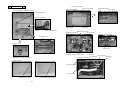
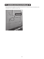
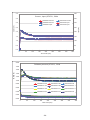
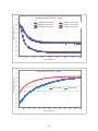
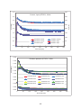
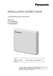
1
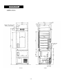
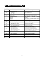
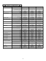
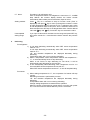
Service Manual Pharmaceutical refrigerator FILE No. MPR-215F SANYO Electric Co., Ltd. Biomedical Business Division SM9910247 Effective models This service manual is effective for following models. Model MPR-215F Product code 823 637 51 823 637 52 823 637 53 823 637 54 Voltage and frequency 115V, 60Hz 220V, 50Hz 220V, 60Hz 230/240V, 50Hz Contents Page Specifications --------------------------------------------------------- 1 -㻌 Structural specifications -㻌 Performance specifications -㻌 Control specifications Dimensions --------------------------------------------------------- 4 Cooling unit parts ---------------------------------------------------- 5 Cooling circuits ---------------------------------------------------- 6 Components on PCB ---------------------------------------------------- 7 Connections on PCB ---------------------------------------------------- 8 Electric components ---------------------------------------------------- 9 Specifications of sensor ---------------------------------------------- 10 Wiring diagram ---------------------------------------------------- 11 Circuit diagram ---------------------------------------------------- 12 ---------------------------------------------- 13 ---------------------------------------------------------- 20 Control specifications Parts layout Note for replacing capillary of freezer Test data ------------------------------ 21 ---------------------------------------------------------- 22 - Pull-down speed - Pull-up speed -㻌 Current and input -㻌 Pull-down pressure - Temperatures of components -㻌 Temperature uniformity (15points measured) -㻌 Amount of power consumption when driving at cycle Instruction manual ---------------------------------------------------- 32 Specifications Structural specifications MPR-215F Item Refrigerator External dimensions Internal dimensions Freezer W540 mm x D557 + (45)*mm x H1794 mm * projection W455 mm x D470 mm x H917 mm Effective capacity 176 L 39 L Exterior Painted steel Interior Styrene resin Insulation Door W420 mm x D342 mm x H267 mm Colored aluminum Rigid polyurethane foamed-in place Painted steel, provided with glass Painted steel window Shelf 5pcs, Hard steel wire on 1pc, Hard steel wire on polyethylene polyethylene coating coating Allowable load: 20kg/shelf Allowable load: 10kg/shelf Inner dimensions; W388 x D325 mm Inner dimensions; W327 x D250 mm Lock 1 / cylinder key Caster 4 Leveling leg 2 Access port 1 at left side (䃥30mm) 1 at left side (䃥30mm) Compressor Hermetic type Output; 55W Hermetic type Output; 55W Refrigerant R-134a Compressor oil 䃐15HT Evaporator Fin and tube type Tube on sheet Condenser Wire and tube type Frame pipe Weight Lamp 86 kg 10W bulb x 1 Power supply Accessories Optional components None Local voltage 1 set of key, 2 large clips (for temperature recorder) Data acquisition system: MTR-5000 Interface board: MTR-480 LAN Interface board: MTR-L03 Temperature recorder for freezer: MTR-4015LH Recorder fixture for MTR-4015LH: MPR-S3 Temperature recorder for freezer & refrigerator: MTR-G3504 Recorder fixture for MTR-G3504: MPR-S7 Temperature recorder for refrigerator: MTR-0621LH -1- Control specifications MPR-215F Item Refrigerator Temp Controller Freezer Microprocessor control system Temperature sensor Temperature display Thermistor Thermistor Digital temperature display: Green LED (Unit:䉝) Display range: -50䉝䡚+50䉝 Switch selectable between refrigerator and freezer Temperature settable +2䉝䡚+14䉝 -35䉝䡚-15䉝 range Alarms High temp. Low temp. Door alarm Range: Set temp.+ 2䉝 ~ + 14䉝 Default: Set temp.+ 5䉝 ALARM lamp blinks and buzzer sounds intermittently after 15min. of delay. Range: Set temp. - 2䉝 ~ - 14䉝 Default: Set temp. - 5䉝 ALARM lamp blinks and buzzer sounds intermittently after 15min. of delay. DOOR lamp illuminates and buzzer delay. Range: Set temp. + 5䉝 ~ + 15䉝 Default: Set temp. + 10䉝 ALARM lamp blinks and buzzer sounds intermittently after 15min. of delay. Range: Set temp. - 5䉝 ~ - 15䉝 Default: Set temp. - 10䉝 ALARM lamp blinks and buzzer sounds intermittently after 15min. of delay. sounds intermittently with 2min. of Remote alarm Maximum contact capacity; 30VDC, 2A Remote alarm activates in temperature alarm or power failure. 0䉝 alarm When chamber temperature is lower than 0䉝, ALARM lamp blinks and buzzer sounds without delay. Self-diagnosis None When sensors are malfunction; zError code and chamber temperature are displayed alternately. zRemote alarm contact activates and buzzer sounds intermittently. Control panel DOOR: Door check-lamp ALARM: Alarm indicator lamp REFRIGERATOR: Temperature display indicator for refrigerator FREEZER: Temperature display indicator for freezer BUZZER: Alarm buzzer stop key REF./FREEZ.: Temperature display changeover key SET: Set key 䠚: Scroll key 䌻: Up arrow key Key lock functions Press the 䠚key for approx. 5 seconds to select key lock status. L0: Unlocked L1: Locked Compressor protection Overload relay and compressor protection sensor -2- Performance specifications MPR-215F Item Refrigerator Freezer 2䉝~14䉝 -30䉝~-20䉝 (AT-5䉝~+35䉝, no load) (AT-5䉝~+30䉝, no load) Temperature control range Noise level 35/36 dB (A scale) (50Hz/60Hz) Maximum pressure Rated voltage 1900 kPa AC115V AC220-240V AC220V AC220V AC110V Rated frequency 60Hz 50Hz 60Hz 50Hz 60Hz Power consumption 180W 155W 170W 145W 175W Usable condition -5䉝~35䉝, 80% R.H. or less -3- Dimensions <MPR-215F> Place to fit power cord Access port <Side> <Front> -4- Cooling unit parts Specifications Parts description Compressor For 110/115V, 60Hz Code For 220~240V, 50Hz Code Power supply For 220V 60Hz Code Power supply Refrigeration oil Cooling system Condenser Type Evaporator Frame pipe Type Accumulator Capillary tube Resistance Length L Outside diameter OD Refrigerant Dryer Condensing fan motor For 110/115V, 60Hz For 220-240V, 50Hz For 220V, 60Hz Cooling fan motor For 110/115V, 60Hz For 220-240V, 50Hz For 220V, 60Hz Refrigerator Freezer FL0528-PA 7FB-0-M101-014-02 Single phase, 110/115V, 60Hz FL0528-SF 7FB-0-M101-014-03 Single phase, 220~240V, 50/60Hz FL0528-SF 7FB-0-M101-014-03 Single phase, 220~240V, 50/60Hz Type䠖䃐15HT Charged q’ty䠖200+/-10ml Air cooling by fan Wire and tube 䃥4.76㽢P40 mm W480mm x 18columns x 1 line ----Fin and tube type 2 lines㽢8 columns 䃥38㽢L125 mm FL0528-PA 7FB-0-M101-014-02 Single phase, 110/115V, 60Hz FL0528-SF 7FB-0-M101-014-03 Single phase, 220~240V, 50/60Hz FL0528-SF 7FB-0-M101-014-03 Single phase, 220~240V, 50/60Hz Type䠖䃐15HT Charged q’ty䠖200+/-10ml Air cooling by fan 0.59MpaG 2000 mm 䃥1.8 mm Charged q'ty䠖 85g Charged q’ty䠖 8g 0.83MpaG 5600 mm 䃥1.8 mm Charged q'ty䠖 85g Charged q’ty䠖 8g R-134a 4XH-9 -----䃥4.0 X T0.5 X L5631 mm Direct cooling tube on sheet type 1 line x 24 columns 䃥30㽢L120 mm R-134a 4XH-9 Type: FL2-011K1M Output: 1W Type: FL2-011K5M Output: 1W Type: FL2-011K5M Output: 1W Type: FL2-011B1MP Output: 1W Type: FL2-012BM5P Output: 1W Type: FL2-012BM5P Output: 1W -5- ---------------- 㻌 㻌 㻌 㻌 㻌 Cooling circuit < Refrigerator > Wire condenser Capillary tube Evaporating pipe Dryer Compressor Accumulator Evaporator < Freezer > Capillary tube Evaporator Frame pipe Dryer Accumulator Compressor 㻌 --- Point to pull vacuum -6- Components on PCB CN1 #1-#3 Switching power supply CN2 #1-#6 MTR-480/MTR-L03 (Option) CN9 #1-#2 F.Power relay CN4 #1-#2 R.Power relay #5-#6 -7CN7 #1-#2 Door SW #3-#4 R.Temp. sensor #5-#6 R.Defrost sensor #7-#8 R.Room thermal sensor #9-#10 R.comp.sensor CN10 #4 Door switch CN11 #1-#2 F.Temp.sensor CN6 #1-#12 Display PCB(CN52) CN5 #1-#6 Display PCB(CN51) CN3 Remote alarm terminal #1 COM #2 N.O. #3 N.C. Connections on PCB The following shows connections of connectors (CN) on temp. control PCB. Connector Connects to Usage CN1 Switching power supply 䠀1 12VDC 䠀3 GND Power supply to PCB. CN2 Interface board MTR-480/L03 for optional connection CN3 Remote alarm terminal 䞉㻌#1 COM 䞉㻌#2 N.O. 䞉㻌#3 N.C. Open between #1 and #2 in normal condition. Close between #1 and #2 in power failure or alarming condition. CN4 #1 - #2: R. power relay #5 - #6: Room lamp relay Control of refrigerator temperature ON/OFF control of refrigerator room lamp CN5 #1 - #6: Display PCB (CN51) Connects to each switches. CN6 #1 - #12: Display PCB (CN52) Connects to each LEDs. CN7 #1 - #2: Door switch #3 - #4: R. temp. sensor #5 - #6: R. defrost sensor #7 - #8: R. room thermal sensor #9 - #10: R. comp. sensor Control of door open and shut Sensing of refrigerator temperature Sensing of pile of frost on evaporator Sensing of temperature rising of refrigerator Sensing of compressor temperature CN8 Unused CN9 #1 - #2: F. power relay Control of freezer temperature CN10 #4: Door switch Control of door open and shut CN11 #1 - #2: F. temp. sensor Sensing of freezer temperature -8- Electric components MPR-215F Compressor R/F PTC Overload relay R/F Cooling fan motor Comp. cooling fan motor Defrost heater F. power relay R. power relay Room lamp relay Room lamp Switching power supply R. comp. sensor R. room thermal sensor R. defrost sensor R. temp. sensor F. temp. sensor Low temp. alarm thermo Thermal protector Door switch Breaker switch Type Code Rated voltage (50/60Hz) Winding resistance C-M(Main) C-S(Aux) Type Rating Type Action to the temp. (No current) OFF ON Action to the current (AT25䉝) Operation time Type Rating Type Rating Temp. fuse Rating Resistance (AT25䉝) Type Contact capacity Coil Type Contact capacity Coil Type Contact capacity Coil Type Clasp Type Rating Type Rating Type Rating Type Rating Type Rating Type Rating Type 㻻㻺 㻻㻲㻲 Type 㻻㻺 㻻㻲㻲 Type Rating Type Rating AC110/115V, 60Hz AC220~240V,50Hz AC220V,60Hz FL0528-PA 7FB-2-M101-014-02 AC100V, 50/60Hz 6.39䃈 7.81䃈 P3T0SAT 3.9䃈 (AT25䉝) 2.8C36C1 FL0528-SF 7FB-2-M101-014-03 AC220-240V, 50Hz 34.3䃈 40.0䃈 PET0SAT 22䃈(AT25䉝) 1.0C36C1 FL0528-RA 7FB-2-M101-014-04 AC220-240V, 50Hz 30.4䃈 30.9䃈 PET0SAT 22䃈(AT25䉝) 1.2C36C3 130+8/-9䉝 60+7/-5䉝 9.6A 10+/-4 sec. FL2-011K1M AC110V, 1W FL2-011BM1P AC110V, 1W 145䉝 46.3W, AC115V 285.6䃈 JC1AF-TM 15A, AC250V DC12V G4F-1123T-U 20A, AC250V DC12V G2R-1A-T 10A, AC250V DC12V 125V, 10W E17 ZWS10-12/J DC12V, 0.85A 502AT 5k䃈(25䉝) 502AT 5k䃈(25䉝) 502AT 5k䃈(25䉝) 502AT 5k䃈(25䉝) 502AT 5k䃈(25䉝) WPF3K-114-010 10.1䉝 2.6䉝 TH-2 18䉝 28䉝 S994 AC250V, 1A BAME2152 AC240V, 15A 130+8/-9䉝 60+7/-5䉝 3.7A 10+/-4 sec. FL2-011K5M AC230V, 1W FL2-011BM5P AC230V, 1W 145䉝 46.3W, AC230V 1142.5䃈 JC1AF-TM 15A, AC250V DC12V G4F-1123T-U 20A, AC250V DC12V G2R-1A-T 10A, AC250V DC12V 110V, 10W E17 ZWS10-12/J DC12V, 0.85A 502AT 5k䃈(25䉝) 502AT 5k䃈(25䉝) 502AT 5k䃈(25䉝) 502AT 5k䃈(25䉝) 502AT 5k䃈(25䉝) WPF3K-114-010 10.1䉝 2.6䉝 TH-2 18䉝 28䉝 S994 AC250V, 1A BAME2152 AC240V, 15A 130+8/-9䉝 60+7/-5䉝 4.5A 10+/-4 sec. FL2-011K5M AC230V, 1W FL2-011BM5P AC230V, 1W 145䉝 46.3W, AC230V 1142.5䃈 JC1AF-TM 15A, AC250V DC12V G4F-1123T-U 20A, AC250V DC12V G2R-1A-T 10A, AC250V DC12V 110V, 10W E17 ZWS10-12/J DC12V, 0.85A 502AT 5k䃈(25䉝) 502AT 5k䃈(25䉝) 502AT 5k䃈(25䉝) 502AT 5k䃈(25䉝) 502AT 5k䃈(25䉝) WPF3K-114-010 10.1䉝 2.6䉝 TH-2 18䉝 28䉝 S994 AC250V, 1A BAME2152 AC240V, 15A -9- Specifications of sensor The following shows temperature and resistance characteristics on each thermistor sensor (type 502AT). Temperature 䠄䉝䠅 Resistance 䠄k䃈䠅 Temperature 䠄䉝䠅 Resistance 䠄k䃈䠅 Temperature 䠄䉝䠅 Resistance 䠄k䃈䠅 䠉50 154.50 䠉7 17.92 12 8.17 䠉45 116.50 䠉6 17.16 13 7.85 䠉40 88.85 䠉5 16.43 14 7.55 䠉35 68.15 䠉4 15.74 15 7.27 䠉30 52.84 䠉3 15.08 16 6.99 䠉25 41.19 䠉2 14.45 17 6.73 䠉20 32.43 䠉1 13.86 18 6.48 䠉19 30.92 0 13.29 19 6.24 䠉18 29.50 1 12.74 20 6.01 䠉17 28.14 2 12.22 25 5.00 䠉16 26.87 3 11.72 30 4.18 䠉15 25.65 4 11.25 35 3.51 䠉14 24.51 5 10.80 40 2.96 䠉13 23.42 6 10.37 45 2.51 䠉12 22.39 7 9.96 50 2.14 䠉11 21.41 8 9.57 55 1.83 䠉10 20.48 9 9.20 60 1.57 䠉9 19.58 10 8.84 䠉8 18.73 11 8.49 - 10 - Wiring diagram - 11 - Circuit diagram - 12 - Control specifications 1. 2. Keys on control panel BUZZER When ALARM lamp flashes, buzzer sounds and remote alarm terminal turns over, press this key to silence the buzzer. When ALARM lamp flashes and buzzer does not sound, press this key to remain the buzzer silence. Remote alarm terminal remains inactive. SET When this key is pressed, the device steps to Setting mode. When this key is pressed again, the setting value can be memorized. REF. / FREEZ. When this key is pressed, temperature display indicator for refrigerator or temperature display indicator for freezer illuminates. The indicator switches to another one every pressing this key. (Scroll key) In the setting mode, a digit which to be changed can be shift between st nd the 1 digit and the 2 digit every pressing this key. When a chamber temperature is displayed, press this key for 5 seconds to display setting Key Lock mode. (“L 0” is displayed) (Up arrow key) In the setting mode, a blinking digit can be changed every pressing this key. When a chamber temperature is displayed, press this key for 5 seconds to step the device to Function mode. (“F00” is displayed) Temperature control Settable range Display range Setting method Unacceptable range: 3. Refrigerator: +2Υ ~ +14Υ Freezer: -35Υ ~ -15Υ -50Υ ~ +50Υ Press REF./FREEZ. Key to select alternative setting temperature for refrigerator or freezer. Press the SET key and change value by pressing key and key. Press SET key again to memorize the value and to return to chamber temperature display. If you input a value which deviates from setting range and press SET key, the buzzer sounds for 1 second and the device remains the previous setting value. Alarms High-temperature alarm: When the chamber temperature is higher than high temperature alarm setting value, ALARM lamp flashes, the numeric display flashes, and the buzzer sounds intermittently after an approx. 15 minutes of delay and remote alarm output is active. Factory default: Set temp. +5Υ for refrigerator Set temp. +10Υ for freezer Low-temperature alarm: When the chamber temperature is lower than low temperature alarm setting value, ALARM lamp flashes, the numeric display flashes, and the buzzer sounds intermittently after an approx. 15 minutes of delay and remote alarm output is active. Factory default: Set temp. -5Υ for refrigerator Set temp. -10Υ for freezer - 13 - 4. 0Υ alarm: This alarm is for refrigerator only. when a temperature sensor for refrigerator is lower than 0Υ, ALARM lamp flashes, the numeric display flashes, the buzzer sounds intermittently without delay and remote alarm output is active. Setting method: Press key for 5 seconds to step to Function mode (“F00” is displayed), then press key to count up through the numbers. A value for high temperature alarm to be input if “F01” is selected, and a value for low-temperature alarm to be input if “F02” is selected. Select one of these and press the SET key to set temperature alarm. Set the desired value with key and key. Press SET key to memorize the value. Unacceptable setting range: If you input a value which deviates from the range and press SET key, the buzzer sounds for 1 second and the device remains the previous value. Defrosting For refrigerator: 1) A unit starts defrosting automatically when DEF sensor temperature reaches -13Υ. A unit stops defrosting automatically when DEF sensor temperature reaches +5Υ. “dF” and chamber temperature are displayed alternately during defrosting. Temperature alarm will not occur during defrosting. 2) When a temperature sensor temperature reaches set temperature + 7Υ, a unit automatically forces to stop defrosting. When a unit forces to stop defrosting for two times, it will be automatically stop defrosting for the next time. 3) A unit automatically starts defrosting when compressor runs for 3~4 hours and DEF sensor temperature is less than 0Υ. When DEF sensor temperature reaches 5Υ, a unit will stop defrosting. For freezer: 1) When setting temperature is 0Υ, the compressor for freezer will stop running. Defrosting for freezer is performed by manual. “dF” and chamber temperature are displayed alternately during defrosting. A temperature alarm will not occur during defrosting. Change setting temperature to restart freezer operation. When the power is interrupted by power failure or turning main power off, a unit will continue to defrost after the power is recovered. - 14 - 5. Error codes E01: Temp. sensor for refrigerator is open circuit E02: Temp. sensor for refrigerator is short circuit E03: Temp. sensor for freezer is open circuit E04: Temp. sensor for freezer is short circuit E05: DEF sensor is open circuit E06: DEF sensor is short circuit E07: Alarm sensor is open circuit E08: Alarm sensor is short circuit E10: Compressor protection sensor is high temperature E11: Compressor protection sensor is open circuit E12: Compressor protection sensor is short circuit E01: When temp. sensor for refrigerator is open circuited, E01 and -50Υ are alternately displayed. When DEF sensor temperature is lower than 0Υ, compressor will turn off. When DEF sensor temperature is higher than 7Υ, compressor will turn on. E02: When temp. sensor for refrigerator is short circuited, E02 and +50Υ are alternately displayed. When DEF sensor temperature is lower than 0Υ, compressor will turn off. When DEF sensor temperature is higher than 7Υ, compressor will turn on. E03: When temp. sensor for freezer is open circuited, compressor will run continuously. E04: When temp. sensor for freezer is short circuited, compressor will run continuously. E05: When DEF sensor is open circuited, a unit will not step to defrosting. E06: When DEF sensor is short circuited, a unit will not step to defrosting. E07: When alarm sensor is open circuited, a unit will not step to defrosting. E08: When alarm sensor is short circuited, a unit will not step to defrosting. E10: When compressor protection sensor is higher than +58Υ, E10 will be emit. When compressor protections sensor is lower than +40Υ, E10 will be eliminated. E11: When compressor protection sensor is open circuited, it is inoperative to protect compressor for refrigerator. E12: When compressor protection sensor is short circuited, it is inoperative to protect compressor for refrigerator. - 15 - 6. Key Lock mode If key is pressed for 5seconds or more when a chamber temperature is displayed, a device steps to Key Lock mode and “L 0” is displayed. Select “1” by pressing Select “0” by pressing key ----- Locked key ----- Unlocked Press SET key to memorize the setting value and a device will automatically return to chamber temperature display. Note) When “Locked” is selected, the device will step to setting mode, but it is unacceptable to change the value. 7. Auto-return Function: 8. If there is no key operation for around 90seconds or more in the setting mode, Key Lock mode or Function mode, the device will automatically return to current chamber temperature display without memorizing the value to be changed. Compressor delay During the cycle, the compressor is forcibly switched off 2minutes since the compressor is forcibly switched off. Compressor delay time is varied when the power is supplied (the microprocessor resets). (See F05) The compressor in freezer starts 15seconds earlier than the compressor in refrigerator. During the cycle, one of those compressor starts 9seconds earlier than another. 9. Function mode F01: F02: F03: F04: F05: F06: *F07: *F08: *F09: *F10: *F11: *F12: *F13: *F14: *F15: *F16: *F17: F21: F22: F24: F25: *F30: Setting of temperature for high temperature alarm for refrigerator Setting of temperature for low temperature alarm for refrigerator Setting of temperature for high temperature alarm for freezer Setting of temperature for low temperature alarm for freezer Setting of compressor delay time Setting of service code (384) Zero adjustment for temp. sensor for refrigerator Zero adjustment for temp. sensor for freezer Compressor continuous running mode (for factory use only) Program running mode (for factory use only) PCB test mode (for PCB manufacturer only) Display of temp. sensor temperature for refrigerator Display of DEF sensor temperature Display of temp. sensor temperature for freezer Display of alarm sensor temperature for refrigerator Display of compressor protection sensor temperature for refrigerator Setting of model code and initialization of non-volatile memory Setting of communication ID Setting of communication mode Linkage between remote alarm and buzzer Setting of Ring Back time Display of ROM version - 16 - F32: Display of fan motor accumulation time *F45: Setting of heater control (for factory use only) F50: Setting of alarm delay time * … It is necessary to input service code (384) prior to use the functions. <How to use Function mode> Press key for 5seconds when chamber temperature display, the device will step to Function mode and “F00” is displayed. Press key to input function code and press SET key. F01: Setting of high temperature alarm setting value for refrigerator. Range: Set temperature +2Υ ~ +14Υ. (Factory default: +5Υ) F02: Setting of low temperature alarm setting value for refrigerator. Range: Set temperature -2Υ ~ -14Υ. (Factory default: -5Υ) F03: Setting of high temperature alarm setting value for freezer. Range: Set temperature +5Υ ~ +15Υ. (Factory default: +10Υ) F04: Setting of low temperature alarm setting value for freezer. Range: Set temperature -5Υ ~ -15Υ. (Factory default: -10Υ) F05: Setting of compressor delay time. (This mode is effective only when the main power is supplied) The aim is to reduce compressor start-up failures and breaker being tripped which are caused by several units starting simultaneously after the power returned from the interruption. Range: 3 ~ 15 minutes (Factory default: 3 minutes) F06: Service code “384” should be input for F07 and latter numerical functions which are marked with * in the page XX~XX. Press SET key to memorize the value and step to Function mode again. It is unnecessary to input service code for F21, F22 and F25. Service code can be memorized unless “000” is input again in “F06” or the main power is turned off. F07: Zero adjustment for temp. sensor for refrigerator (Input range: -9.9Υ ~ +9.9Υ) Service code should be input prior to use this function. In “F07” display, press SET key to show “00.0” (Factory default). Change a value by pressing key and key Press SET key to memorize the value. Ex) When actual 1/2H temperature is 4.2Υ and set temperature is 5.0Υ, input “–0.8” (Calculation: 4.2-(5.0)) to the value which is displayed. F08: Zero adjustment for temp. sensor for freezer (Input range: -9.9Υ ~ +9.9Υ) Service code should be input prior to use this function. In “F08” display, press SET key to show “00.0” (Factory default). Change a value by pressing key and key. Press SET key again to memorize the value. - 17 - F12: Display of temp. sensor temperature for refrigerator. (Unit: 0.1Υ) Service code should be input prior to use this function. The display gives the temperature to the first decimal place, but as the display area is 3-digit, the “-“ in minus temperatures is not displayed when the temperature is –20Υ or lower. (Ex. An actual temperature, –35.0Υ will be displayed as “35.0”). F13: DEF sensor temperature is displayed. (Unit: 1Υ) Service code should be input prior to use this function. F14: Display of temp. sensor temperature for freezer (Unit: 0.1Υ) Service code should be input prior to use this function. The display gives the temperature to the first decimal place, but as the display area is 3-digit, the “-“ in minus temperatures is not displayed when the temperature is –20Υ or lower. (Ex. An actual temperature, –35.0Υ will be displayed as “35.0”). F15: Display of alarm sensor temperature for refrigerator (Display range: -50~+110Υ) Service code should be input prior to use this function. F16: Display of compressor protection sensor temperature for refrigerator Service code should be input prior to use this function. F17: Setting of model code and initialization of non-volatile memory Service code should be input prior to use this function. <Setting of model code> In “F17” display, press SET key to show “001” (Factory defualt). Change the value to “002” (MPR-215F) by using key and press SET key again to memorize the value. <Initial values of non-volatile memory> Set temperature for refrigerator: +5Υ Set temperature for freezer: -30Υ Key Lock: 0 (OFF) High temp. alarm for refrigerator: Set temperature +5Υ Low temp. alarm for refrigerator: Set temperature -5Υ High temp. alarm for freezer: Set temperature +10Υ Low temp. alarm for freezer: Set temperature-10Υ Zero adjustment for refrigerator: 0Υ Zero adjustment for freezer: 0Υ Communication ID: 000 Communication mode: 000 Ring back time: 030㸦30minutes㸧 Linkage between remote alarm and buzzer: Not linked Temp. alarm delay time: 015 (15minutes) F21: Setting of serial communication ID (Input range: 000 ~ 255) 000: Not communicated - 18 - F22: Setting of serial communication mode Control mode (the 3rd digit) 0 : Local (Factory default) 1: Remote 0 : 2400 bps (Factory default) Baud rate (the 2nd digit) 1: 4800 bps 2: 9600 bps The 1st digit is unused. Note) When you set control mode in “remote”, it is impossible to change set temperature through the unit. F24: Linkage between remote alarm and buzzer 000 : Not linked (Factory default) 001 : Linked F25: Setting of Ring Back time (Input range: 000, 010, 020, 030, 040, 050, 060) (Unit: Minute) 000: Ring back is inactive F30: Display of ROM version Service code should be input prior to use this function. F32: Display of fan motor accumulation time (Unit: Year) F50: Setting of temp. alarm delay time (Input range: 000, 001, 002, 003, 004, 005, 006, 007, 008, 009, 010, 011, 012, 013, 014, 015 Unit: Minute) 000: Not delayed 10. Differential value Refrigerator Compressor turns on Compressor turns off Set temperature Set temperature +0.3Υ -0.3Υ 11. Offset value The device is offset as follows in order to correct the differential between the temperature detected by temp. sensor and the actual temperature in the center of chamber. Refrigerator Freezer 12. Freezer Compressor turns on Compressor turns off Set temperature Set temperature +0.4Υ -0.8Υ Offset value Temp. sensor temperature -0.5Υ Temp. sensor temperature -1.0Υ Remote Alarm Normal In alarm or power failure N.O. – COM. Open Close - 19 - N.C. - COM Close Open Parts layout Connection for interface Cover for power switch 䛆Upper back side䛇 Remote alarm terminal Power switch <Inside of refrigerator, mullion is removed> R. room thermal sensor Fan cover is removed Wiring diagram Cooling fan Power cord Low temp. alarm thermo. Swtiching power supply Room lamp relay 䛆Electric box at ceiling䛇 䛆Back side of control panel䛇 R. defrost sensor R. temp. sensor Display PCB Temp. control PCB R. power relay F. power relay Compressor R 䛆Cooling unit䠄Lower front䠅䛇 Sensing bar of low temp. alarm thermo. <Inside of freezer> Dryer for refrigerafor R. comp. sensor F. temp. sensor (Covered) - 20 - F. temp. sensor (Cover is removed) Dryer for freezer Compressor L Note for replacing capillary of freezer After removing wire condenser, cut a part of rear panel which is marked in the picture by drawing a line temporalily on the 7 dowels of the rear cover. dowel welding point - 21 - Test data Note) All the data are the reference only. 50 Pulldown speed (AT35䉝䠅, 50Hz 40 Internal temperature (䉝) 30 220V50Hz R-side 1/2Air 220V50Hz F-side 1/2Air 230V50Hz R-side 1/2Air 230V50Hz F-side 1/2Air 240V50Hz R-side 1/2Air 240V50Hz F-side 1/2Air 20 10 0 -10 -20 -30 -40 0 60 120 180 240 300 360 420 480 Time scale (min) 50 Pullup speed (AT35䉝䠅, 50Hz Internal temperature (䉝) 40 30 20 10 R-side 1/2Air F-side 1/2Air 0 -10 -20 -30 -40 0 60 120 180 240 300 360 420 Time scale (min) - 22 - 480 540 600 660 720 4.0 400 Current , Input (AT35䉝䠅, 50Hz 3.5 350 230V50Hz Current 240V50Hz Current 220V50Hz Input 230V50Hz Input 240V50Hz Input 300 2.5 250 2.0 200 1.5 150 1.0 100 0.5 50 0.0 0 0 60 120 180 240 300 360 420 480 Time scale (min) 2.000 Pulldown pressure (AT35䉝䠅, 50Hz 1.800 Pd,Ps(MPa) 1.600 1.400 1.200 1.000 0.800 220V50Hz R-Pd 220V50Hz R-Ps 220V50Hz F-Pd 220V50Hz F-Ps 230V50Hz R-Pd 230V50Hz R-Ps 230V50Hz F-Pd 230V50Hz F-Ps 240V50Hz R-Pd 240V50Hz R-Ps 240V50Hz F-Pd 240V50Hz F-Ps 0.600 0.400 0.200 0.000 0 60 120 180 240 Time scale (min) - 23 - 300 360 420 480 Input (W) Current (A) 3.0 220V50Hz Current 50 Pulldown speed (AT35䉝䠅, 60Hz 40 Internal temperature (ଇ) 30 110V60Hz R-side 1/2Air 110V60Hz F-side 1/2Air 115V60Hz R-side 1/2Air 115V60Hz F-side 1/2Air 220V60Hz R-side 1/2Air 220V60Hz F-side 1/2Air 20 10 0 -10 -20 -30 -40 0 60 120 180 240 300 360 420 480 Time scale (min) 50 Pullup speed (AT35䉝䠅, 60Hz Internal temperature (䉝) 40 30 20 10 R-side 1/2Air F-side 1/2Air 0 -10 -20 -30 -40 0 60 120 180 240 300 360 420 Time scale (min) - 24 - 480 540 600 660 720 4.0 400 350 3.0 300 2.5 250 2.0 200 1.5 150 1.0 100 0.5 110V60Hz Current 115V60Hz Current 220V60Hz Current 110V60Hz Input 115V60Hz Input 220V60Hz Input 50 0.0 0 0 60 120 180 240 300 360 420 480 Time scale (min) 2.000 Pulldown pressure (AT35䉝䠅, 60Hz 1.800 Pd,Ps(MPa) 1.600 1.400 1.200 1.000 0.800 110V60Hz R-Pd 110V60Hz R-Ps 110V60Hz F-Pd 110V60Hz F-Ps 115V60Hz R-Pd 115V60Hz R-Ps 115V60Hz F-Pd 115V60Hz F-Ps 220V60Hz R-Pd 220V60Hz R-Ps 220V60Hz F-Pd 220V60Hz F-Ps 0.600 0.400 0.200 0.000 0 60 120 180 240 Time scale (min) - 25 - 300 360 420 480 Input (W) Current (A) Current , Input (AT35䉝䠅, 60Hz 3.5 Temperatures of components (Reference Data on Maximum cooling) Ambient temperature 30䉝 110䠲60Hz 115V60Hz 220䠲50Hz 230V50Hz 240V50Hz 220䠲60Hz Compressor case bottom Discharge pipe Wire and tube condensor outlet Evaporator inlet Evaporator outlet R-side Suction pipe Air temperature at center of chamber 䠬䡀 䠬䡏 Current Input Compressor case bottom Discharge pipe Frame pipe outlet Evaporator inlet Evaporator outlet F-side Suction pipe Air temperature at center of chamber 䠬䡀 䠬䡏 Current Input Current TOTAL Input 䚷䚷(䉝) 䚷䚷(䉝) 51.7 48.4 51.8 48.5 49.4 45.3 49.5 45.3 49.8 45.5 50.3 47.1 䚷䚷(䉝) 38.8 38.9 38.6 38.7 38.5 39.0 䚷䚷(䉝) 䚷䚷(䉝) 䚷䚷(䉝) -23.2 -23.7 31.9 -23.2 -23.6 31.9 -22.4 -16.4 32.4 -22.4 -16.7 32.4 -22.4 -16.4 32.4 -23.9 -24.6 30.7 䚷䚷(䉝) -13.5 -13.6 -11.1 -11.1 -11.1 -14.7 (䠩䠬䠽) (䠩䠬䠽) 䚷䚷(䠝) 䚷䚷(䠳) 䚷䚷(䉝) 䚷䚷(䉝) 䚷䚷(䉝) 䚷䚷(䉝) 䚷䚷(䉝) 䚷䚷(䉝) 1.013 0.110 1.35 95.7 55.1 51.5 40.0 -37.8 -38.4 29.8 1.014 0.110 1.37 97.6 55.4 51.7 40.1 -37.9 -38.5 29.8 1.013 0.119 0.53 70.6 52.1 47.8 33.6 -37.3 -37.8 31.0 1.011 0.118 0.55 72.3 52.4 47.9 33.6 -37.3 -37.9 31.0 1.009 0.119 0.57 74.1 53.0 48.3 33.5 -37.4 -37.9 30.9 0.999 0.098 0.62 92.1 53.7 48.0 33.8 -39.7 -40.2 29.3 䚷䚷(䉝) -35.3 -35.3 -34.1 -34.1 -34.1 -35.0 (䠩䠬䠽) (䠩䠬䠽) 䚷䚷(䠝) 䚷䚷(䠳) 䚷䚷(䠝) 䚷䚷(䠳) 0.873 0.057 1.20 67.9 2.80 187.4 0.873 0.057 1.24 69.8 2.88 192.7 0.871 0.077 0.50 53.9 1.16 143.2 0.872 0.077 0.52 56.1 1.21 150.1 0.868 0.077 0.55 58.1 1.27 154.2 0.864 0.057 0.55 66.4 1.28 177.6 Ambient temperature 35䉝 110䠲60Hz 115V60Hz 220䠲50Hz 230V50Hz 240V50Hz 220䠲60Hz Compressor case bottom Discharge pipe Wire and tube condensor outlet Evaporator inlet Evaporator outlet R-side Suction pipe Air temperature at center of chamber 䠬䡀 䠬䡏 Current Input Compressor case bottom Discharge pipe Frame pipe outlet Evaporator inlet Evaporator outlet F-side Suction pipe Air temperature at center of chamber 䠬䡀 䠬䡏 Current Input Current TOTAL Input 䚷䚷(䉝) 䚷䚷(䉝) 56.7 54.4 57.5 55.0 55.5 52.1 55.6 52.1 56.2 52.5 56.0 53.4 䚷䚷(䉝) 43.9 44.6 44.3 44.2 44.3 44.3 䚷䚷(䉝) 䚷䚷(䉝) 䚷䚷(䉝) -20.7 -20.9 36.1 -20.4 -20.4 36.7 -19.4 -13.5 37.4 -19.5 -13.4 37.4 -19.4 -13.8 37.6 -21.3 -21.4 35.3 䚷䚷(䉝) -10.3 -10.0 -7.5 -7.6 -7.6 -11.1 (䠩䠬䠽) (䠩䠬䠽) 䚷䚷(䠝) 䚷䚷(䠳) 䚷䚷(䉝) 䚷䚷(䉝) 䚷䚷(䉝) 䚷䚷(䉝) 䚷䚷(䉝) 䚷䚷(䉝) 1.151 0.124 1.32 91.8 59.4 56.6 45.2 -34.8 -35.4 33.5 1.172 0.126 1.35 93.3 60.4 57.5 46.1 -34.5 -35.1 33.9 1.168 0.132 0.55 75.5 57.9 54.1 39.0 -34.5 -35.1 36.1 1.165 0.132 0.55 76.0 58.3 54.4 38.9 -34.5 -35.1 36.0 1.169 0.133 0.58 78.9 59.4 55.3 39.0 -34.5 -35.0 36.0 1.149 0.113 0.63 95.1 59.3 54.4 39.1 -37.0 -37.4 33.8 䚷䚷(䉝) -32.2 -31.9 -31.2 -31.2 -31.1 -32.0 (䠩䠬䠽) (䠩䠬䠽) 䚷䚷(䠝) 䚷䚷(䠳) 䚷䚷(䠝) 䚷䚷(䠳) 0.999 0.067 1.19 67.3 2.77 183.3 1.008 0.069 1.23 68.7 2.85 187.6 1.009 0.084 0.50 56.1 1.18 150.4 1.007 0.085 0.51 57.4 1.21 153.7 1.010 0.085 0.55 60.7 1.29 163.8 0.998 0.065 0.55 67.7 1.29 181.7 Note) The data are the reference only. - 26 - Temperature Uniformity data (15points measured) Note) The data are the reference only. 䠘Measurement points䠚 䚷䚷䚷h1䠖H×5% 䚷䚷䚷h2䠖H×50% 䐢 䚷 㼔㻝 䐟 䐡 䐣 㻴 䐠 Refrigerato r 䐤 䐧 䐦 䐥 㼔㻌㻞 䐨 㻌 䐫 䐭 䐟 䐢 䐠 䚷 䐡 䐣 䐧 㻴 䐤 䐬 䚷 䐨 䚷 䐩 㼔㻝 䐥 㼔㻞 䐦 䐫 䐭 d1䠖D×5% d2䠖D×50% w1䠖W×5% w2䠖W×50% 㻌 㼐㻞 㻰 㻌 㼐㻝 䐪 㻌 㼐㻝 Freezer (15points) 㼔㻝 䐪 㼔㻝 䐬 䐩 㼣㻝 㼣㻝 㻌 㻌 㼣㻞 㻌 㼃 - 27 - Note) This data does not represent a guarantee of product performance. 䠘Conditions䠚 Ambient temperature: 20䉝 Load: Unloaded 䠘Distribution data䠚 Unit:䉝 Freezer Refrigerator Ambient temperature 20䉝 Set value (Refrigerator/Freezer) : 5/-30䉝 Set value (Refrigerator/Freezer) : 5/-20䉝 Middle of Middle of Differential Maximum Minimum Differential Maximum Minimum cycle cycle 7.3 0.4 4.0 ±3.5 7.4 0.3 4.0 ±3.6 䐟 7.1 1.8 4.5 ±2.7 7.2 1.8 4.5 ±2.7 䐠 7.0 1.9 4.5 ±2.6 7.0 1.6 4.4 ±2.7 䐡 6.9 1.9 4.4 ±2.5 7.0 1.8 4.4 ±2.6 䐢 7.0 2.1 4.5 ±2.5 7.0 2.0 4.5 ±2.5 䐣 6.3 2.9 4.6 ±1.7 6.4 2.8 4.6 ±1.8 䐤 6.9 2.7 4.7 ±2.1 6.9 2.6 4.7 ±2.2 䐥 6.6 3.5 5.0 ±1.6 6.7 3.4 5.0 ±1.7 䐦 6.2 3.8 4.9 ±1.2 6.3 3.8 5.0 ±1.3 䐧 6.7 4.7 5.7 ±1.0 6.7 4.7 5.7 ±1.0 䐨 7.0 3.3 5.0 ±1.9 6.9 3.1 4.9 ±1.9 䐩 7.2 3.9 5.4 ±1.7 7.1 3.8 5.4 ±1.7 䐪 6.9 2.8 4.8 ±2.1 6.8 2.8 4.7 ±2.0 䐫 6.7 2.8 4.7 ±2.0 6.7 2.7 4.6 ±2.0 䐬 6.9 3.8 5.3 ±1.6 6.8 3.7 5.2 ±1.6 䐭 Average 4.8 4.8 -19.9 -24.7 -22.3 ±2.4 -29.4 -32.8 -31.1 ±1.7 䐟 -16.7 -19.4 -18.1 ±1.4 -24.8 -27.3 -26.1 ±1.3 䐠 -19.1 -22.4 -20.8 ±1.7 -28.0 -30.2 -29.1 ±1.1 䐡 -19.7 -24.1 -21.9 ±2.2 -29.0 -32.3 -30.7 ±1.7 䐢 -16.1 -18.7 -17.4 ±1.3 -24.0 -26.2 -25.1 ±1.1 䐣 -19.7 -20.8 -20.3 ±0.6 -28.9 -29.8 -29.4 ±0.5 䐤 -19.9 -20.7 -20.3 ±0.4 -29.1 -29.6 -29.4 ±0.3 䐥 -20.2 -21.0 -20.6 ±0.4 -29.4 -30.0 -29.7 ±0.3 䐦 -20.1 -21.3 -20.7 ±0.6 -29.3 -30.2 -29.8 ±0.4 䐧 -19.9 -20.7 -20.3 ±0.4 -29.0 -29.6 -29.3 ±0.3 䐨 -20.5 -24.9 -22.7 ±2.2 -30.2 -33.8 -32.0 ±1.8 䐩 -20.1 -24.5 -22.3 ±2.2 -29.9 -33.5 -31.7 ±1.8 䐪 -20.2 -27.5 -23.9 ±3.7 -29.8 -35.8 -32.8 ±3.0 䐫 -20.0 -23.5 -21.8 ±1.8 -29.5 -32.1 -30.8 ±1.3 䐬 -19.9 -23.1 -21.5 ±1.6 -29.5 -32.1 -30.8 ±1.3 䐭 Average -21.0 -29.8 - - 28 - Note) This data does not represent a guarantee of product performance. 䠘Conditions䠚 Ambient temperature: 30䉝 Load: Unloaded 䠘Distribution data䠚 Unit:䉝 Freezer Refrigerator Ambient temperature 30䉝 Set value (Refrigerator/Freezer) : 5/-30䉝 Set value (Refrigerator/Freezer) : 5/-20䉝 Middle of Middle of Differential Maximum Minimum Differential Maximum Minimum cycle cycle 7.2 0.1 3.7 ±3.6 7.3 0.2 3.8 ±3.6 䐟 7.5 3.0 5.1 ±2.3 7.5 3.2 5.2 ±2.2 䐠 7.1 1.5 4.3 ±2.8 7.1 1.5 4.4 ±2.8 䐡 7.0 1.4 4.3 ±2.8 7.0 1.5 4.4 ±2.8 䐢 7.2 2.0 4.6 ±2.6 7.2 2.1 4.7 ±2.6 䐣 6.4 3.1 4.8 ±1.7 6.5 3.2 5.0 ±1.7 䐤 7.2 3.5 5.3 ±1.9 7.3 3.5 5.4 ±1.9 䐥 6.9 3.3 5.3 ±1.8 7.0 3.3 5.4 ±1.9 䐦 6.4 4.1 5.3 ±1.2 6.4 4.1 5.4 ±1.2 䐧 7.4 5.4 6.5 ±1.0 7.5 5.4 6.6 ±1.1 䐨 7.4 3.6 5.5 ±1.9 7.4 3.6 5.6 ±1.9 䐩 7.8 4.2 6.1 ±1.8 7.8 4.2 6.1 ±1.8 䐪 7.2 3.1 5.2 ±2.1 7.2 3.2 5.3 ±2.0 䐫 7.0 3.1 5.1 ±2.0 7.0 3.2 5.1 ±1.9 䐬 7.6 4.3 6.0 ±1.7 7.4 4.3 6.0 ±1.6 䐭 Average 5.1 5.2 -19.7 -24.7 -22.2 ±2.5 -28.7 -32.8 -30.8 ±2.1 䐟 -15.8 -18.5 -17.2 ±1.4 -24.0 -26.1 -25.1 ±1.1 䐠 -18.7 -22.1 -20.4 ±1.7 -27.6 -31.2 -29.4 ±1.8 䐡 -19.4 -24.0 -21.7 ±2.3 -28.6 -32.1 -30.4 ±1.8 䐢 -14.9 -17.3 -16.1 ±1.2 -23.1 -24.7 -23.9 ±0.8 䐣 -19.3 -20.4 -19.9 ±0.5 -28.3 -29.6 -29.0 ±0.7 䐤 -19.5 -20.2 -19.9 ±0.4 -28.5 -29.4 -29.0 ±0.4 䐥 -19.9 -20.5 -20.2 ±0.3 -28.9 -29.8 -29.4 ±0.5 䐦 -19.7 -20.9 -20.3 ±0.6 -28.7 -30.1 -29.4 ±0.7 䐧 -19.4 -20.1 -19.8 ±0.4 -28.5 -29.3 -28.9 ±0.4 䐨 -20.4 -24.4 -22.4 ±2.0 -29.8 -33.2 -31.5 ±1.7 䐩 -20.0 -23.9 -22.0 ±2.0 -29.4 -32.7 -31.1 ±1.7 䐪 -20.1 -26.8 -23.5 ±3.4 -29.2 -34.7 -32.0 ±2.8 䐫 -19.6 -22.8 -21.2 ±1.6 -28.8 -31.5 -30.2 ±1.4 䐬 -19.6 -22.6 -21.1 ±1.5 -28.9 -31.5 -30.2 ±1.3 䐭 Average -20.5 -29.3 - - 29 - - 30 - Internal temperature (䉝) Internal temperature (䉝) -40 -35 -30 -25 -20 -15 -10 -5 0 5 10 -40 -35 -30 -25 -20 -15 -10 -5 0 5 10 10 20 30 Time scale (min) 40 Refrigerator䐫 50 Freezer䐫 Freezer䐡 Refrigerator䐡 0 10 Freezer䐦 Refrigerator䐦 20 30 Time scale (min) Refrigerator䐫 40 50 Freezer䐫 Freezer䐡 Refrigerator䐡 Refrigerator Set temp:5䉝, Freezer Set temp:-20䉝, AT30䉝 0 Freezer䐦 Refrigerator䐦 Refrigerator Set temp:5䉝, Freezer Set temp:-20䉝, AT20䉝 60 60 Internal temperature (䉝) Internal temperature (䉝) -40 -35 -30 -25 -20 -15 -10 -5 0 5 10 -40 -35 -30 -25 -20 -15 -10 -5 0 5 10 10 20 30 Time scale (min) 40 Refrigerator䐫 Freezer䐫 50 60 Freezer䐡 Refrigerator䐡 0 10 20 Freezer䐦 Refrigerator䐦 30 Time scale (min) 40 Refrigerator䐫 Freezer䐫 50 60 Freezer䐡 Refrigerator䐡 Refrigerator Set temp:5䉝, Freezer Set temp:-30䉝, AT30䉝 0 Freezer䐦 Refrigerator䐦 Refrigerator Set temp:5䉝, Freezer Set temp:-30䉝, AT20䉝 - 31 - 2.66 2.74 2.32 2.46 2.59 2.67 110V60Hz 115V60Hz 220V50Hz 230V50Hz 240V50Hz 220V60Hz 3.08 2.95 2.81 2.64 3.20 3.13 5/-30 䉝 2.86 2.75 2.61 2.48 2.88 2.84 5/-20 䉝 3.29 3.12 3.00 2.85 3.41 3.29 5/-30 䉝 20䉝 Note:This data does not represent a guarantee of product performance. 5/-20 䉝 15䉝 Set value (Refrigerator/Freezer) Ambient temperature Amount of power consumption when driving at cycle ᲶAmount of power consumptionᲸ 2.99 2.88 2.70 2.59 3.01 2.95 5/-20 䉝 3.42 3.24 3.11 2.95 3.52 3.41 5/-30 䉝 23䉝 3.33 3.12 2.98 2.86 3.29 3.25 5/-20 䉝 3.77 3.54 3.41 3.27 3.88 3.77 5/-30 䉝 Unit䠖kWh/day 30䉝