1
Service Manual
Biomedical Freezer
FILE No.
MDF-U730M
SANYO Electric Co., Ltd.
Biomedical Business Division
RoHS
This product does not contain any hazardous substances prohibited by the RoHS Directive.
(You will find ‘RSF’ mark near the rating plate on the RoHS compliant product.)
WARNING
* You are requested to use RoHS compliant parts for maintenance or repair.
* You are requested to use lead-free solder.
SM9910191
Effective model
This service manual is effective for following model.
Model name
Product code
MDF-U730M
823 010 54
Voltage and Frequency
220/230/240V
50Hz
Contents
㩷
Page
Features
---------------------------------------
1
Specifications
---------------------------------------
2
- Structural specifications
- Control specifications
- Performance specifications
Dimensions
------------------------------------------------------
5
Refrigeration circuits
----------------------------------------
6
Connections on PCB
---------------------------------------------
7
Electric parts
-----------------------------------------------
Specifications of sensor
----------------------------------
8
9
Wiring diagram
------------------------------------
10
Circuit diagram
------------------------------------
11
Control specifications
Test data
---------------------------------------
12
---------------------------------------
15
- Pull-down and pull-up data
- Pressure data
- Current and power consumption data
- Temperature uniformity – 15points measured
Instruction
㩷
Manual
---------------------------------------
19
Features
䕔Cooling performance
Refrigerant circuit contains HFC refrigerant that effects to environment little.
Latest cooling system reduces negative factor to global environment. With ambient
temperature shown at 35䉝, while chamber temperature maintains -30䉝.
䕔Easy operation
* New type door handle makes an operator’s strength less to open the door.
* Levels of shelves are adjustable.
* 2” storage container (MDF-T07ST) for optional components
䕔Environmental friendly
* HCFC free refrigerant R-404A is used in the refrigeration circuit.
* CP urethane foaming for insulation (HCFC free)
1
㩷
Specifications
㩷
ŶStructural specifications
Item
Name
External dimensions
Internal dimensions
Effective capacity
Door
Insulation
Exterior
Interior
Shelf
Door latch
Door lock
Door handle
Caster
Fixture
Access port
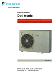
Refrigeration circuit
Compressor
Evaporator
Condenser
Refrigerant
Refrigerant oil
Power supply
Weight
Accessories
Optional component
MDF-U730M
Biomedical Freezer
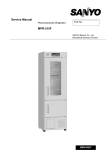
W770 × D830 × H1955 (mm)
W650 × D710 × H1520 (mm)
690 L
1, painted steel
Rigid polyurethane foamed-in place
Painted steel
Painted steel
4, polyurethane coated wire
Size; W626 x D620 (mm)
Max. load; 50kg/shelf
1 on the left side (padlock attachable)
1 on the upper side
1 on the left side
4
2 on the back side
1 port on the left side, 1 port on the top of unit Diameter; Ǿ30mm
Primary cooling system
Hermetic type, Output; 400W
Tube on sheet type
Wire and tube type
R-404A
E-68NT1
Local voltage
150 Kg
1 set of key, 1 scraper,
2 large & 2 small nylon clips (for temperature recorder)
Automatic temperature recorder (MTR-G85) + Mounting kit (MPR-S7)
Automatic temperature recorder (MTR-4015LH) + Mounting kit (MPR-S30)
2 sets of basket (MDF-T07SC), 3 sets of shelves (MDF-T07ST)
2
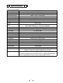
ŶControl specifications
Item
Temp. controller
Temperature sensor
Temperature display
Temperature
Door
Alarms
Power failure
Remote alarm
Compressor
abnormal temp.
Control panel
Key lock function
Sensor abnormality
Compressor protection
MDF-U730M
Microcomputer control system
Temperature setting range: -18͠㨪-35͠ (Unit; 1͠)
Temperature control range: -20͠㨪-30͠
Non-volatile memory
Temperature default setting: -30͠
Thermistor sensor
LED digital display
Display range: 0͠㨪-40͠ (Unit; 1͠)
Note) ‘HI’ is displayed when the temperature is equal or higher than 1͠.
‘LO’ is displayed when the temperature is equal or lower than -41͠.
+5͠~+15͠ for High temperature alarm (Default; +10͠)
-5͠~-15͠ for Low temperature alarm (Default; -10͠)
ALARM lamp blinks and buzzer sounds intermittently with 15min. delay.
Remote alarm activates.
DOOR lamp is lit and buzzer is emitted with 2min. delay.
ALARM lamp blinks, buzzer sounds intermittently and remote alarm
activates. Temperature display is gone off.
(Present chamber temperature is displayed for 5 seconds with BUZZER
key pressed.)
Remote alarm terminal 3P; Max. DC30Vޔ2A
NC-COM, NO-COM
Buzzer sounds intermittently.
Lamps: ALARM, DOOR
Alarm buzzer stop key: BUZZER
Alarm test key: ALARM TEST
Defrost key: DEF
Set key: SET
Digit shift key:
Numerical value shift key:
Press key for 5 seconds to display;
L0: Key lock is off L1: Key lock is on
When any failure is occurred in sensor,
zError code and ‘HI’ or ‘LO’ are alternately displayed
zRemote alarm activates
zBuzzer sounds intermittently
Overload relay and compressor protection cycle
㩷
3
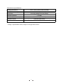
ŶPerformance specifications
Cooling performance
-20͠㨪-30͠ (AT5͠㨪35͠, no load)
Rated power consumption
Noise level
260W/280W (230V/240V)
42 dB {A} (background noise 20dB)
Maximum pressure
2.78 MPa
Maximum power consumption
365W/390W (230V/240V)
Maximum current
Usable conditions
2.3A/2.6A (230V/240V)
AT; +5͠~+35͠
Humidity: Less than 80㧑RH
* Design or specifications will be subject to change without notice.
4
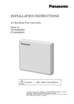
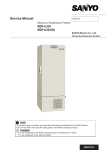
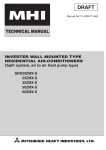
Dimensions
5
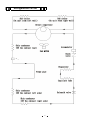
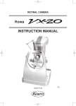
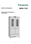
Refrigeration circuit
6
Connections on PCB
The following shows connections of connector on Temp. Control PCB.
Connector
Connects to
Usage
#1: Comp. relay
CN1
To control compressor on/off
#4: Solenoid valve
#5: Breaker switch
CN2
#1 - #2: Comp. relay
To control compressor on/off
Modular terminal blocks
CN3
Remote alarm contact outputs.
#1: N.O.
In normal condition, open for #2-#1 and
#2: COM
closed for #2-#3.
#3: N.C.
CN5
#1 - #5: Display PCB
To connect to each LED.
CN6
#1 - #12: Display PCB
To connect to each LED.
#3 - #4: F sensor
To detect temperature in outlet pipe
#5 - #6: Door switch
To detect door ajar
#3 – #4: Comp. sensor
To detect temperature in compressor
CN7
CN8
7
Electric parts
MDF-U730M
Compressor
Starting relay
Overload relay
Starting capacitor
Running capacitor
Condensing fan motor
Breaker switch
Power cord
Solenoid coil
Comp.relay
220/230/240VAC, 50Hz
Type
C-2SN400L5W
Code
807 780 25
Rated voltage (50/60Hz)
220-240V, 50Hz
Winding resistance C-S(Main)
6.251㱅
C-R(Aux)
18.79㱅
Type
AMVL-300A
Pick up voltage
185~217VAC(50Hz)
Drop out voltage
60~120VAC(50Hz)
Type
P12MUF
Action to the temp. (no current) ON: 130㫧8㷄 OFF: 69㫧10㷄
Action to the current (AT25͠)
12A
Operation time
6~15 sec.
Rating
300VAC, 30MF
Rating
400VAC, 4MF
Type
FL2-C021R5MP
Rating
230VAC, 2W
Type
BAM215131
Rating
250V, 15A
Type
GTVD-2,3
Rating
16A, 250V
Type
NEVAC240V
Rating
240VAC, 50/60Hz
Type
852-W-1A-C1
Rating
12VDC
8
Specifications of sensor
The following shows temperature and resistance characteristics on thermal sensor.
<Type: SS148-202H372G-1400>
Temperature
Resistance
Temperature
Resistance
Temperature
Resistance
炷Υ炸
炷kȍ炸
炷Υ炸
炷kȍ炸
炷Υ炸
炷kȍ炸
-40
49.220
-25
21.085
-10
9.681
-39
46.411
-24
19.977
-5
7.578
-38
43.776
-23
18.932
0
5.972
-37
41.305
-22
17.948
5
4.739
-36
38.935
-21
17.020
10
3.784
-35
36.808
-20
16.146
15
3.041
-34
34.764
-19
15.320
20
2.459
-33
32.843
-18
14.541
25
2.000
-32
31.039
-17
13.806
30
1.635
-31
29.343
-16
13.112
35
1.345
-30
27.749
-15
12.457
40
1.112
-29
26.249
-14
11.837
45
0.924
-28
24.839
-13
11.252
50
0.771
-27
23.511
-12
10.699
-26
22.262
-11
10.176
<Type: SS128-203H397G-4610>
Temperature
Resistance
Temperature
Resistance
Temperature
Resistance
炷Υ炸
炷kȍ炸
炷Υ炸
炷kȍ炸
炷Υ炸
炷kȍ炸
0
65.56
75
29.66
5
50.93
80
25.19
10
39.88
85
21.49
15
31.46
90
18.40
20
25.00
95
15.82
25
20.00
100
13.66
30
16.11
105
11.83
35
13.05
40
10.64
45
87.30
50
72.00
55
59.70
60
49.76
65
41.68
70
35.08
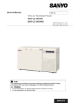
9
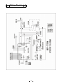
Wiring Diagram
10
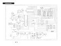
Circuit Diagram
11
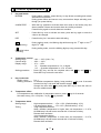
㻌 Control specifications
1.
Key and Switch
BUZZER
:
During alarm condition, press this key to stop buzzer sounding and remote
alarm does not activate.
During power failure and sensor error, remote alarm keeps activating even
though you press this key.
ALARM TEST
:
With this key pressed to activate alarm test mode to be forcibly step into
alarm condition. Buzzer and remote alarm are forcibly activated.
Press this key again to cancel alarm test condtion.
SET
:
Press this key once to activate set mode, press the key again to store the
value to be changed.
DEF
:
Press this key for 5 seconds to start defrosting.
During setting mode, the blinking digit shifts among the 1st digit or the 2nd
digit or 3rd digit.
(Digit shift key)
During setting mode, count the blinking digit up every pressed this key.
(Numerical value
shift key)
2.
Temperature control
Setting range
: -18䉝 ~ -35䉝 (Unit; 1䉝)
Control range
: -20䉝 ~ -30䉝
Display range
:
0䉝 ~ -40䉝
‘HI’ … Chamber temperature is 1䉝 or higher
‘LO’ … Chamber temperature is -41䉝 or lower
Setting procedure : Press SET key and set the required value with
Press SET key to store the set value.
key and
key.
3.
Key Lock mode
Setting range
: 0 or 1
Setting procedure: In chamber temperature display, keep pressing
key over 5 seconds
to enter into Key Lock mode with buzzer sounds.
Change the value with
key and press SET key to store the value in
the non-volatile memory.
4.
Temperature offset
For temperature zero calibration for temperature sensor, press
Set value among -9䉝~+9䉝(Unit; 1䉝) by
key pressed.
5.
Temperature alarm
Setting range
:
Timing
:
key for 5 seconds.
High temperature alarm … +5䉝~+15䉝 (Default setting: 10䉝)
Low temperature alarm …. -5䉝~-15䉝 (Default setting: -10䉝)
<High temperature alarm>
When chamber temperature is higher than set temperature + 5~15䉝,
ALARM lamp is lit and buzzer sounds with 15 minutes of delay.
Remote alarm activates.
<Low temperature alarm>
When chamber temperature is lower than set temperature - 5~15䉝,
ALARM lamp is lit and buzzer sounds with 15 minutes of delay.
Remote alarm activates.
12
Setting procedure
:
Keep pressing
key and
key over 5 seconds to enter into setting
mode for temperature alarm (F00). Set “F01” for high temperature alarm
or “F02” for low temperature alarm. Press SET key to set the value to be
changed with the 1st digit blinks. Press SET key again to store the value
in the non-volatile memory.
Note) z Temperature alarm does not activate when unit starts operating and
defrosting.
z Temperature alarm activates after the compressor stops once.
6.
Power failure alarm
ALARM lamp blinks, buzzer sounds, remote alarm activates and the display is gone off during
power failure.
If you press BUZZER key, buzzer stops sounding and the current chamber temperature is
displayed for 5 seconds.
Any other keys but BUZZER key are inoperative.
For the compressor protection, compressor starts operation with delay after the power retrieves
within 4 minutes since the power was failed.
7.
Door alarm
When the door is ajar, DOOR lamp is lit.
After 2 minutes elapse since the door ajar, the buzzer sounds.
Remote alarm does not activate.
8.
Compressor temperature abnormality
When temperature in compressor sensor is over than 95䉝 for 2 seconds, compressor stops
operation with buzzer sounds and remote alarm activates.
When temperature in compressor sensor is equal or lower than 60 䉝 , compressor starts
operation again and buzzer stops sounding.
9.
Thermal sensor abnormality
When thermal sensor is failed, error code is displayed, buzzer sounds and remote alarm
activates. Compressor is kept operating.
When thermal sensor is short circuited, E01 and ‘HI’ are alternately displayed.
When thermal sensor is open circuited, E01 and ‘LO’ are alternately displayed.
10.
Defrosting
Press DEF key for 5 seconds to start defrosting with buzzer sounds. Compressor stops
operation. Current chamber temperature and ‘dF’ are alternately displayed.
During defrosting or after defrosting completes, press DEF key for 5 seconds to stop defrosting
and start unit cooling.
For the compressor protection, compressor starts operation with 4 minutes of delay even though
defrosting is forcibly done.
11.
Auto return function
If there is not any key operation for 90 seconds during setting mode, unit automatically reverts to
chamber temperature display without the setting value memorized.
13
12.
Compressor delay time
<After the power is supplied>
The compressor starts operation with 9 seconds of delay since the power is supplied.
<During cycle operation>
When the unit is in cycle operation, the compressor does not start until 4 minutes elapse once
the compressor stops operation.
13.
Temperature to control compressor
When chamber temperature is reached to set temperature + 0.3䉝, compressor starts operation.
When chamber temperature is reached to set temperature – 0.3䉝, compressor stops operation.
14
Test data
* All the data are the reference only.
y
AT35䉝, No load
Pull-down data
230V 50Hz
240V 50Hz
40
1/2H chamber air temp. 䠷䉝䠹
30
20
10
0
-10
10
-20
-30
-40
0
1
2
3
4
5
6
7
8
9
10
11
Time 䠷H䠹
Pull-up data
AT35䉝, No load
40
1/2H chamber air ttemp. 䠷䉝䠹
30
20
10
0
-10
-20
-30
-40
0
1
2
3
4
5
Time 䠷H䠹
15
6
7
8
AT35䉝 No
AT35䉝,
N lload
d
Pressure data
Ps
1.6
2.8
1.4
2.4
1.2
2
1
1.6
0.8
1.2
0.6
0.8
0.4
0.4
0.2
0
Ps [MPa]
Pd [MPa]
Pd
3.2
0
0
1
2
3
4
5
6
7
8
9
10
11
Time [H]
ධຊ 㼇㼃㼉
㻠㻡㻜
㻥
㻠㻜㻜
㻤
㻟㻡㻜
㻣
㻟㻜㻜
㻢
㻞㻡㻜
㻡
230V power consumption
240V power consumption
230V current
240V current
㻞㻜㻜
㻝㻡㻜
㻠
㻟
㻝㻜㻜
㻞
㻡㻜
㻝
㻜
㻜
㻜㻌
㻝㻌
㻞㻌
㻟㻌
㻠㻌
㻡㻌
㻢㻌
㛫 㼇㼔㼉
16
㻣㻌
㻤㻌
㻥㻌
㻝㻜㻌
㻝㻝㻌
㟁ὶ 㼇㻭㼉
AT35䉝, No load
Current and power consumption data
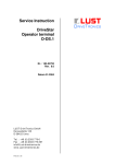
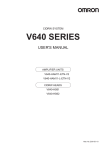
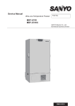
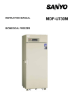
Temperature uniformity data (15 points measured)
*Following data are the reference only.
<Test conditions>
䊶Power source: 230V50Hz
䊶AT: 20㷄, 30㷄
䊶No load
Back
(1)
Front
(2)
(5)
Upper measured points
(4)
(1)~(4): 5% (H) from the top of interior
5% (D) and (W) from each corner
(3)
(5): Center from each corner
5%(H) from the top of interior
Middle measured points
(7)
(6)
(10)
(9)
(6)~(9): 5% (D) and (W) from each corner
1/2(H)
(8)
(10): Center from each corner
1/2(H)
1/2᳂
Ჾ
᳑
Lower measured points
(12)
(11)
(15)
(14)
(13)
Left
Right
(11)~(14): 5%(H) from Bottom of interior
5%(D) and (W) from each corner
(15): Center from each corner
5%(H) from Bottom of interior
17
<Temperature uniformity>
* Reference data
(Unit: 㷄䋩
AT20㷄
Lower
Middle
Upper
Measured
points
SV-20㷄
Temp. Range
(1)
-23.1
±2.3
(2)
(3)
(4)
-23.1
-21.3
±1.9
±1.3
±1.2
(5)
(6)
(7)
(8)
(9)
(10)
(11)
(12)
(13)
(14)
(15)
Accuracy
Variation
Amount of
power
consumption
[kWh/day]
-21.3
-21.7
-22.6
-21.5
-20.7
-20.8
-21.7
-20.7
-20.4
-20.1
-20.4
-21.4
-1.7
-20
-0.1
-3.1
3.29
SV-25㷄
Temp. Range
-26.0
-26.0
-24.8
-24.7
-24.7
±1.4
±2.3
±2.2
-26.3
-26.0
-24.5
-24.6
-25.4
±0.8
±0.9
±0.8
-24.5
-24.3
±1.1
±0.8
±0.8
-23.9
-24.2
-25.2
±0.8
±0.9
㷄
㷄
-0.4
-25
+1.1
-1.3
3.25
AT30㷄
SV-30㷄
Temp. Range
-29.9
-30.0
-28.9
±2.5
±2.1
±1.3
±1.3
-28.9
-28.6
±1.9
±2.2
±2.4
-30.5
-30.5
-28.9
-28.9
-29.8
±0.9
±1.1
±0.9
-28.7
-28.6
±1.3
±1.0
±0.9
-28.2
-28.4
-29.5
±1.0
±1.1
㷄
㷄
+0.2
-30
+1.8
-0.5
3.94
18
SV-20㷄
Temp. Range
-21.9
-22.3
-20.6
±2.5
±2.4
±1.6
±1.5
-20.4
-20.5
±2.2
±1.8
±2.0
-21.7
-21.8
-19.7
-19.9
-20.7
±0.9
±1.1
±0.9
-19.9
-19.8
±1.5
±0.8
±0.8
-19.4
-19.7
-20.7
±0.9
±1.0
㷄
㷄
-0.7
-20
+0.6
-2.3
3.84
SV-25㷄
Temp. Range
-24.9
-25.2
-23.9
±1.7
±1.6
±1.1
±0.9
-23.7
-23.7
±1.0
±2.1
±2.4
-25.2
-25.4
-23.4
-23.5
-24.4
±0.7
±0.8
±0.6
-23.4
-23.5
±0.9
±0.8
±0.6
-23.0
-23.3
-24.3
±0.8
±0.8
㷄
㷄
+0.6
-25
+2.0
-0.4
3.82
±2.4
±2.3
±1.5
±1.6
SV-30㷄
Temp.
Range
-29.0 ±2.2
-29.2 ±2.2
-28.5 ±1.5
-28.2
-28.0
±1.9
±2.0
±2.3
-29.8
-30.0
-28.4
-28.4
-29.2
±0.9
±1.2
±1.0
-28.2
-28.4
±1.2
±0.9
±0.9
-28.0
-28.0
-29.2
±1.0
±1.2
㷄
㷄
+0.8
-30
+2.0
-0.0
4.90
±1.4
±1.9
±1.3
±1.5
±0.9
±1.0
±0.9
±0.9
±0.8
±0.7
±0.9
±1.0
㷄
㷄